

Page 1
VR Series - Power Conversion Modules
Overview:
The unit converts a 24VAC and/or 24VDC input into a regulated 5VDC or 12VDC output.
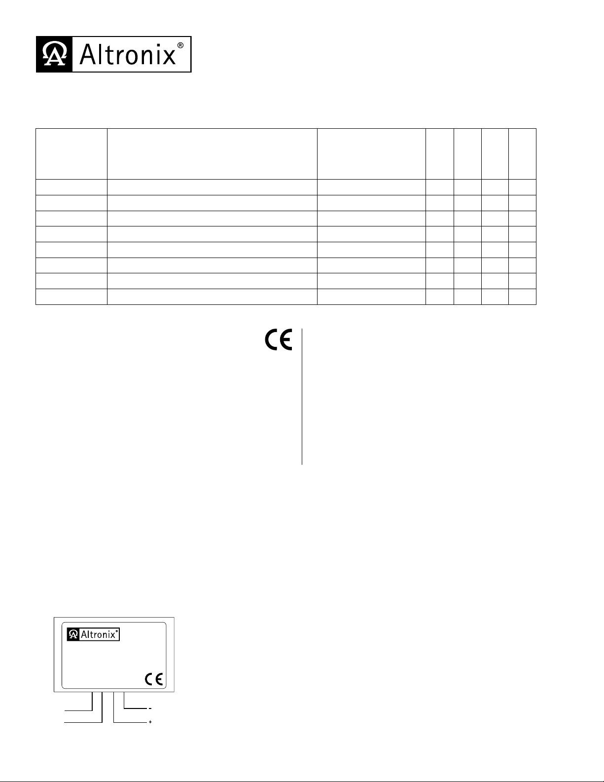
Reference Chart:
Altronix
Model Number Input Output
VR1 24VAC/20VA or higher / 24VDC 12VDC @ 1 amp max. ---
VR1T 24VAC/20VA or higher / 24VDC 12VDC @ 1 amp max. --- --- ---
VR2T 24VAC/20VA or higher / 24VDC 12VDC @ 0.5 amp max. --- --- ---
VR3T 24VDC 12VDC @ 2 amp max. --- ---
VR4T 24VDC 12VDC @ 3 amp max. --- ---
VR5T 24VAC/50VA or higher / 24VDC 12VDC @ 3 amp max. --- --- ---
VR5BT 24VAC/50VA or higher / 24VDC 12VDC @ 3 amp max.
VR1TM5 16VAC/24VAC/20VA or higher /12 or 24VDC 5VDC @ 1 amp max. --- --- ---
Specifications:
Battery
Charging
3
Cable
Assembly
3
--- ---
Screw
Terminal
--- ---
3
3
Spring
Terminal
3
3
---
---
3
3
3
Agency Listing:
• CEEuropeanConformity.
Input:
• Input24VACor24VDC.
Output:
• 5VDC(VR1TM5 ) or 12VDC output.
• Filteredandelectronicallyregulatedoutput.
• Built-inoverloadprotection.
Applications:
• Powerfor12VDCCCTVcamerasandaccessories,
Fiber Optic Transmitters, REX PIR’s, Prox Readers, etc.
Visual Indicators:
• PowerLEDindicator.
Features:
• Modularconnector/cableassemblyfacilitates
ease of wiring.
• Compactdesignallowsforintegrationinawiderange
of camera housings.
Dimensions (W x D x H approx.):
VR5T / VR5BT:
3.375” x 2.5” x 1.125” (85.7mm x 63.5mm x 28.6mm)
All other units:
1.625” x 2.375” x 1” (41.28mm x 60.32mm x 25.4mm)
Installation Instructions:
Installing VR1 (Fig. 1, pg. 1):
1. Mount unit in proximity to the device. Affix one side of velcro (supplied) to the unit and place the second side of the velcro
in the desired location.
2. Connect Yellow lead and Purple lead to 24VAC transformer or 24VDC power source*.
3. Measure output voltage and check polarity before connecting devices, in order to avoid potential damage.
4. Connect Red lead [Pos. +] and Black lead [Neg. --- ] to device to be powered.
5. LED will illuminate when power is present.
*For CE compliance use a Class 2 Power-Limited Power Source.
Fig. 1
24VAC/VDC
Input
VR1
24VDC/24VAC
Yellow
Purple Red
altronix.com
12VDC
+ Output --
Made in U.S.A.
Black
12VDC Output
Voltage Regulator
24VAC/24VDC Input to
12VDC Output @ 1 amp max.
Input
Page 2
TP
TP
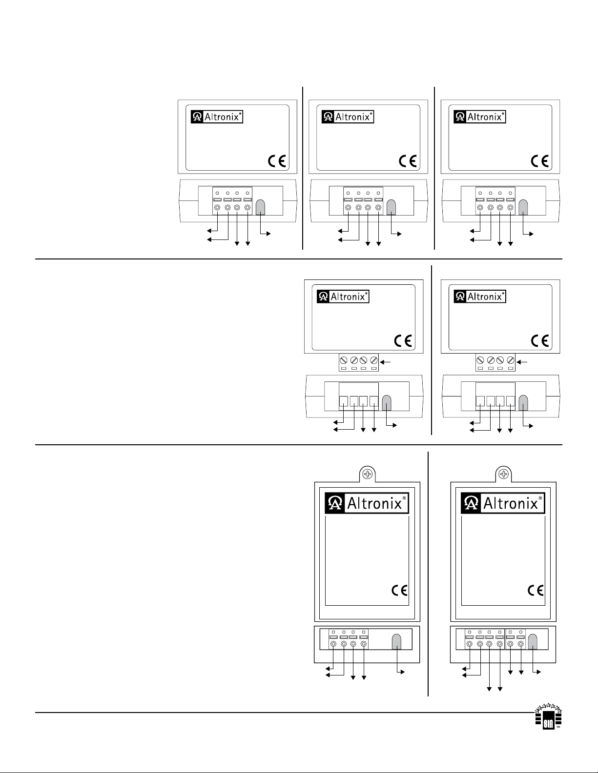
Installing VR1T, VR1TM5, VR2T (Figs. 2-4, pg. 2):
1. Mount unit in proximity to the device. Affix one side of velcro (supplied) to unit and place the second side of the velcro
in the desired location.
2. Connect 24VAC transformer or 24VDC source* to the terminals marked [24VDC/24VAC Input].
3. Measure output voltage and
check polarity before
connecting devices, in order
to avoid potential damage.
4. Connect device to be
powered to the terminals marked
[+ Output --- ].
5. LED will illuminate when
Fig. 2
VR1T
Voltage Regulator
24VAC/24VDC Input to
12VDC Output @ 1 amp max.
12VDC
24VDC/24VAC
+ Output --
Input
altronix.com
Made in U.S.A.
Fig. 3
VR1TM5
24VDC/24VAC
Made in U.S.A.
Voltage Regulator
24VAC/24VDC Input to
5VDC Output @ 1 amp max.
12VDC
+ Output --
Input
altronix.com
Fig. 4
VR2T
Voltage Regulator
24VAC/24VDC Input to
12VDC Output @ 0.5 amp max.
12VDC
24VDC/24VAC
+ Output --
Input
power is present.
*For CE compliance use a
Class 2 Power-Limited
Power Source.
altronix.com
Made in U.S.A.
24VAC/VDC
Input
12VDC Output
Power
LED
Installing VR3T, VR4T (Figs. 5-6, pg. 2):
1. Mount unit in proximity to the device. Affix one side of
velcro (supplied) to the unit and place the second side of the
velcro in the desired location.
2. Connect 24VDC source* to the terminals
marked [24VDC + Input --- ].
3. Measure output voltage and check polarity before connecting
devices, in order to avoid potential damage.
4. Connect device to be powered to the terminals marked
[--- Output +].
5. LED will illuminate when power is present.
*For CE compliance use a Class 2 Power-Limited
Power Source.
Installing VR5T, VR5BT (Figs. 7-8, pg. 2):
1. Mount unit in proximity to the device. Use a proper fastener
and/or wall anchor when securing unit to the wall.
2. Connect 24VAC transformer or 24VDC source* to the
terminals marked [Input].
3. Measure output voltage and check polarity before connecting
devices, in order to avoid potential damage.
4. Connect device to be powered to the terminals
marked [--- OUT + ].
5. LED will illuminate when power is present.
6. For VR5BT (Fig. 8, pg. 2) - when the use of stand-by
batteries is desired, they must be lead acid or gel type.
Connect battery to terminals marked [--- BAT +].
*For CE compliance use a Class 2 Power Limited
Power Source.
24VAC/VDC
Fig. 5
VR3T
Fig. 7
Input
12VDC Output
Voltage Regulator
24VDC Input to
12VDC Output @ 2 amp max.
12VDC
24VDC
+ Output --
+ Input --
24VDC
Input
12VDC Output
VR5T
Voltage Regulator
24VAC/24VDC Input to
12VDC Output @ 3 amp max.
altronix.com Made in U.S.A.
INPU
+
Power
LED
altronix.com
Made in U.S.A.
Removable
Terminal Block
Power
LED
OWER--- OUT
24VAC/VDC
Input
Fig. 6
VR4T
+ Input --
24VDC
Input
Fig. 8
VR5BT
Voltage Regulator
w/Battery Charging
24VAC/24VDC Input to
12VDC Output @ 3 amp max.
altronix.com Made in U.S.A.
INPU
12VDC Output
altronix.com
12VDC
+ Output --
Made in U.S.A.
Terminal Block
+
Voltage Regulator
24VDC Input to
12VDC Output @ 3 amp max.
24VDC
12VDC Output
Power
LED
Removable
Power
LED
OWER--- OUT +--- BAT
24VAC/VDC
Altronix is not responsible for any typographical errors. Product specifications are subject to change without notice.
140 58th Street, Brooklyn, New York 11220 USA, 718-567-8181, fax: 718-567-9056
web site: www.altronix.com, e-mail: info@altronix.com, Lifetime Warranty, Made in U.S.A.
IIVRseries - Rev. 070709 G26M
Input
12VDC Output
Power
LED
24VAC/VDC
Input
12VDC Output
Battery
Charging
Power
LED
MEMBER
 Loading...