

Page 1

CCTV Rack Mount Power Supplies
Installation Guide
Models Include:
Vertiline8 Vertiline8D
- 24VAC or 28VAC @ 5 amp - 24VAC or 28VAC @ 5 amp
- Eight (8) fuse protected outputs - Eight (8) PTC protected outputs
Vertiline83 Vertiline83D
- 24VAC or 28VAC @ 10 amp - 24VAC or 28VAC @ 10 amp
- Eight (8) fuse protected outputs - Eight (8) PTC protected outputs
Rev. 031808
More than just power.
TM
Page 2
Overview:
Altronix Vertiline CCTV Rack Mount Power Supplies provide 8 power outputs in a space saving 1U EIA 19” rack mount
chassis which may be rack, wall or shelf mounted. The units feature individually selectable 24VAC and/or 28VAC power
outputs with surge suppression. Vertiline CCTV Rack Mount Power Supplies are also available in sixteen (16) and twentyfour (24) output models with various power ratings.
Specifications:
• Selectable 115V
• Eight (8) individually selectable 24VAC or 28VAC
power outputs with OFF position.
• Eight (8) power LED indicators.
• External blade fuses or PTC protected outputs.
• Surge suppression.
• Illuminated power disconnect circuit breaker with
manual reset.
AC 60 Hz/230VAC 50/60 Hz input.
• IEC 320 - 3-wire grounded line cord (detachable).
• Removable terminal blocks with locking screw flange.
• Ease of installation saves time and eliminates costly labor.
• Compact 1U rack mount chassis.
• Fits standard EIA 19” rack.
• Units can be rack, wall or shelf mounted.
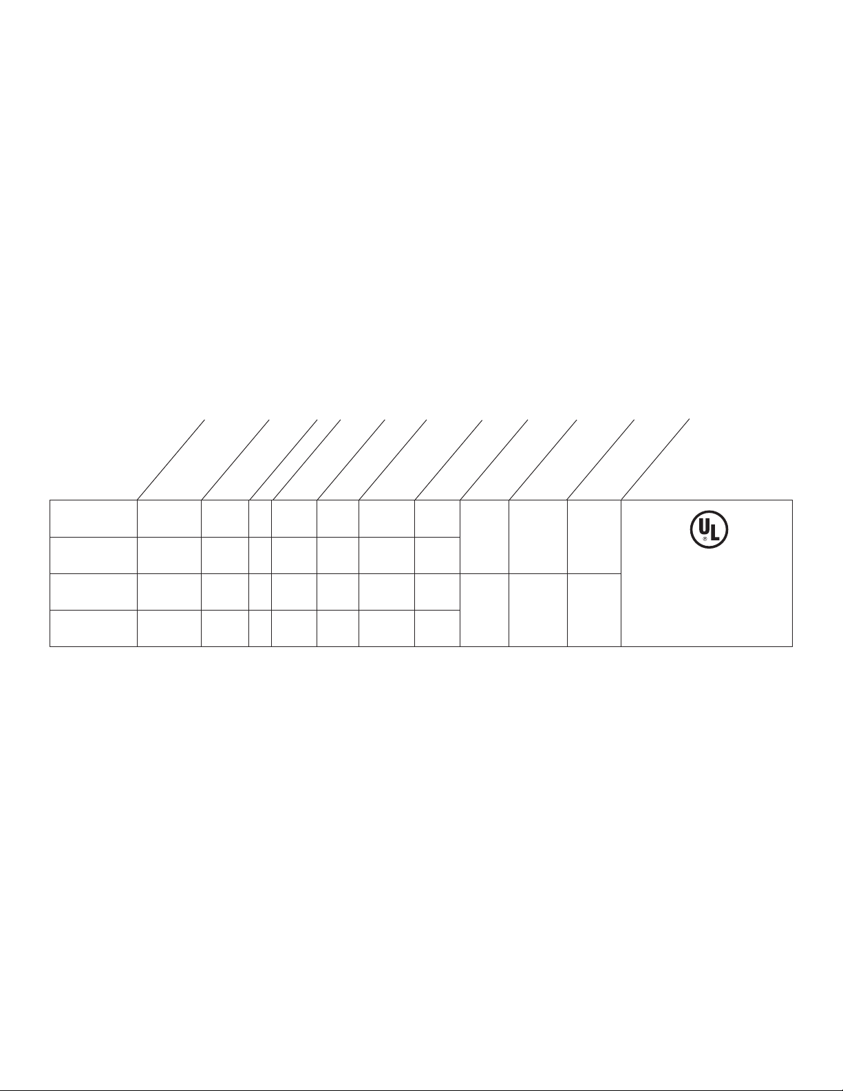
Eight (8) Output Rack Mount Configuration Reference Chart:
Altronix
Model
Number
Vertiline8
Vertiline8D
Vertiline83
Vertiline83D
Voltage (VAC)
Output
24VAC or
28VAC
24VAC or
28VAC
24VAC or
28VAC
24VAC or
28VAC
Total Output Current (Power)
5 amp 8
5 amp 8
10 amp 8
10 amp 8
Number of Outputs
Output Protection
Fused -- 3 amp 3 amp
-- PTC 2.5 amp --
Fused -- 3 amp 3 amp
-- PTC 2.5 amp --
Output Protection
Class 2 Rated Power Limited
(max. per output)
Current
Fuse Rating
10 amp 1.5 amp .8 amp
15 amp 3 amp 1.5 amp
Input Current
Main Fuse Rating
115VAC 60Hz
Input Current
230VAC 50/60Hz
Agency Listings
UL Listed for
CCTV Equipment
Commercial
(UL 2044).
WARNING: To reduce the risk of fire or electric shock, do not expose the unit to rain or
moisture. This installation should be made by qualified service personnel and should conform to
all local codes and in accordance with the National Electrical Code.
Installation Instructions:
1. Set the input voltage selector switch located on the left side of the Vertiline unit (facing front panel) for
115VAC or 230VAC operation (Fig. 1c, pg. 4).
2.
Attach mounting brackets to Vertiline unit for rack or wall mount installation (Figs. 4-5, pg. 7). Affix rubber pads to
Ve
rtiline for shelf installation (Fig. 6, pg. 7).
3. Secure the unit in a rack, mount unit to a w
3” from any video monitors). When installing the unit in a rack allow for one half of a U spacing above the unit
for ventilation.
4. Plug the grounded AC line cord (included) into the IEC 320 connector of the Vertiline unit (Fig. 1f, pg. 4).
Inser
t the plug end of the line cord into a g
5. Set illuminated master power disconnect circuit breaker to the (ON) position (Fig
6. Select 24V
(Fig. 1b, pg. 4).
7.
Measure output v
All terminals with common suffix (P) “1P, 2P ...” are the same polarity.
8. Set illuminated master power disconnect circuit breaker to the (OFF) position (Fig. 3, pg
- 2 - Vertiline8
AC or 28VAC power output for cameras 1-8 with the corresponding voltage adjustment switches
oltage before connecting cameras. This helps avoid potential damage.
all or place unit on a shelf as desired (unit should be spaced at least
rounded AC receptacle.
. 3, pg. 6).
. 6).
Page 3

9. Connect the power outputs of terminals marked [1P & 1N] to the power inputs of camera 1 (Fig. 2, pg. 5).
Repeat this step for each additional camera (Outputs 2-8). After wiring is completed insert terminal block into the
corresponding connector and secure by tightening the screws.
10. Upon completion of wiring, set illuminated master power disconnect circuit breaker to the
ON (RESET) position (Fig. 3, pg. 6).
1
1
. The power LEDs (Green) on the faceplate for Outputs 1-8 will illuminate when AC power is present
(Fig. 1a, pg. 4). If any of these LEDs are off, a loss of AC power output may be due to a blown fuse or a
tripped PTC caused b
y a shor
t circuit or overload condition. If all of the LEDs are OFF there may be a complete
loss of supply power to the Vertiline unit or the illuminated master power disconnect circuit breaker is in the OFF
position or the main fuse 1-8 is blown (Fig. 1d, pg. 4).*
To restore the power output for Vertiline8 or Vertiline83:
1- Switch corresponding output voltage switch to the OFF position (Fig. 1b, pg. 4).
2-
Eliminate the troub
le condition.
3- Replace the corresponding automotive blade fuse.*
4- Switch output voltage switch to the 24VAC or 28VAC position as desired (Fig. 1b, pg. 4).
To restore the power output for Vertiline8D or Vertiline83D:
1- Switch corresponding output voltage switch to the OFF position (Fig. 1b, pg. 4).
2-
Eliminate the troub
le condition.
3- Allow 1 minute for PTC to cool off.
4- Switch output voltage switch to the 24VAC or 28VAC position as desired (Fig. 1b, pg. 4).
*Note: Replace fuses with same type and rating:
Output fuses are rated @ 3 amp for all models.
Main fuse ratings:
10 amp for
V
ertiline8 and Vertiline8D.
Automotive
Blade Fuse
15 amp for Vertiline83 and Vertiline83D.
Vertiline8 - 3 -
Page 4

AC POWER
1
2
3 4 5
6
7 8
28VAC
OFF
24VAC
Main Fuse
1-8
12345678
12345678
N
P
N
P
N
P
N
P
N
P
N
P
N
P
N
P
OFF
RESET
AC POWER
Main Fuse
1-8
N
P
N
P
N
P
N
P
N
P
N
P
N
P
N
P
1c - Input Voltage
115VAC 220VAC
Switch: Selects
115VAC/230VAC
50/60Hz (switch is
located on the left
side of the unit).
1g - IEC 320
Connector: 115VAC
60Hz/230VAC
1f - Output Fuses:
Automotive
blade fuses.
50/60Hz (grounded
line cord included).
1b - Output voltage switches:
Selects 24VAC or 28VAC
1a - LED(s) 1-8:
or OFF for each output.
Power LED indicators.
1e - Power
Outputs: 24VAC
or 28VAC.
1d - Main Fuse:
Protects the
transformer
against overload.
Vertiline8, Vertiline8D, Vertiline83
or Vertiline83D (front)
Vertiline8 or Vertiline83 (rear)
Vertiline8D or Vertiline83D (rear)
Fig. 1
- 4 - Vertiline8
chassis. The output PTCs are located on the inside of the rack mount chassis.
Vertiline8D and Vertiline83D do not have output fuses on the rear of the rack mount
Page 5

AC POWER
Main Fuse
1-8
12345678
N
P
N
P
N
P
N
P
N
P
N
P
N
P
N
P
1
2
3 4 5
6
7 8
28VAC
OFF
24VAC
OFF
RESET
Typical Hookup:
Fig. 2
Vertiline8 - 5 -
Page 6

1.625"
8.5"
.75"
19.125"
17.625"
(ON)
AC POWER
1
2
34 5678
28VAC
OFF
24VAC
Main Fuse
1
-8
NPNPNPN
P
NPNPNPN
P
OFF
RESET
5678 1234
The lightning flash with ar
presence of an insulated “DANGEROUS VOLTAGE” within the products enclosure that may be of sufficient
magnitude to constitute an electric shock.
The exclamation point within an equilateral triangle is intended to alert the user to the presence of important
operating and maintenance (servicing) instructions in the literature accompanying the appliance.
1U EIA 19” Rack Mount Chassis Mechanical Drawing & Dimensions:
1.625”H x 19.125”W x 8.5”D
ro
w head symbol within an equilateral triangle is intended to alert the user to the
CAUTION: To reduce the risk of electric shock do not open enclosure. There are
no user ser
le parts inside. Refer servicing to qualified service personnel.
viceab
REAR
TOP & BOTTOM
Fig. 3
Power switch with built-in circuit breaker:
FRONT
OFF position - Switch not Illuminated. Outputs not pow
RESET (ON) position - Switch illuminated. Outputs powered.
Circuit breaker tripped - Switch not Illuminated. Power LEDs on faceplate
are not illuminated. Outputs not powered.
To reset circuit breaker set power switch to the ON (RESET) position
(Fig. 3, pg. 6).
ered.
- 6 - Vertiline8
Page 7

Mounting Options:
B
A
C
B
A
C
A
B
Rack Mount Installation
1- Remove factory installed screws from both sides of rack chassis (Fig. 4a).
2- Install mounting brackets (A) on the left and right side of rack chassis using the
two (2) flat head screws (B) (included) (Fig. 4b).
3-
Place unit into desired EIA 19” rack position and secure with mounting scre
Fig. 4
ws (not included) (Fig. 4c).
Fig. 4a
Top Top
Fig. 4b
Fig. 4c
To
Front
F
ront
Left
Left
Front Left
Remove
Wall Mount Installation
1- Install mounting brackets (A) on the left and right side of rack chassis using
two (2) flat head screws (B) (included) (Fig. 5a).
2- Place unit at desired location and secure with mounting scre
Caution: It is necessary to make sure mounting screws are securely fastened to a beam when installing.
Fig. 5
Fig. 5a
Fig. 5b
ws (not included) (Fig. 5b).
p
Shelf Installation
1- Position and affix rubber pads (C) (included) at each
corner on the bottom of the unit (Fig. 6).
2- Place unit in desired location.
Fig
. 6
Left Side
Mounting Hardware (Included):
Two (2) mounting brackets
Six (6) flat head screws
for mounting brackets.
Four (4) rubber pads.
Rubber Pad
Vertiline8 - 7 -
Page 8

Notes:
Altronix is not responsible for any typographical errors.
Altronix Corp.
140 58th Street, Brooklyn, New York 11220 USA, 718-567-8181, fax: 718-567-9056
web site: www.altronix.com, e-mail: info@altronix.com, Lifetime Warranty, Made in U.S.A.
IIVertiline8Series J10H
- 8 - Vertiline8
MEMBER
 Loading...