


CCTV Rack Mount Power Supplies
Installation Guide
Models Include:
Vertiline24C Vertiline24CD
- 24VAC or 28VAC @ 10A - 24VAC or 28VAC @ 10A
- Twenty-four (24) fuse protected outputs - Twenty-four (24) PTC protected outputs
Vertiline246C Vertiline246CD
- 24VAC or 28VAC @ 14A - 24VAC or 28VAC @ 14A
- Twenty-four (24) fuse protected outputs - Twenty-four (24) PTC protected outputs
Rev. 031808
More than just power.
TM
Overview:
Altronix Vertiline CCTV Rack Mount Power Supplies provide 24 power outputs in a space saving 1U EIA 19” rack mount
chassis which may be rack, wall or shelf mounted. The units feature individually selectable 24VAC and/or 28VAC power
outputs with surge suppression. Vertiline CCTV Rack Mount Power Supplies are also available in eight (8) and sixteen
(16) output models with various power ratings.
Specifications:
Input:
• 115VAC 60 Hz.
Output:
• Twenty-four (24) individually selectable 24VAC
or 28VAC power outputs with OFF position.
• Twenty-four (24) external blade fuse or PTC
protected outputs.
• Surge suppression.
Features:
• Twenty-four (24) power LED indicators.
Features (cont’d):
• Illuminated master power disconnect circuit breaker
with manual reset.
• IEC 320 - 3-wire grounded line cord (detachable).
• Removable terminal blocks with locking screw flange.
Mechanical:
• Units can be rack, wall or shelf mounted.
• Modular 1U standard EIA 19” rack mount chassis.
• Enclosure Dimensions (H x W x D approx.):
1.625” x 19.125” x 8.5” (41.3mm x 486mm x 216mm).
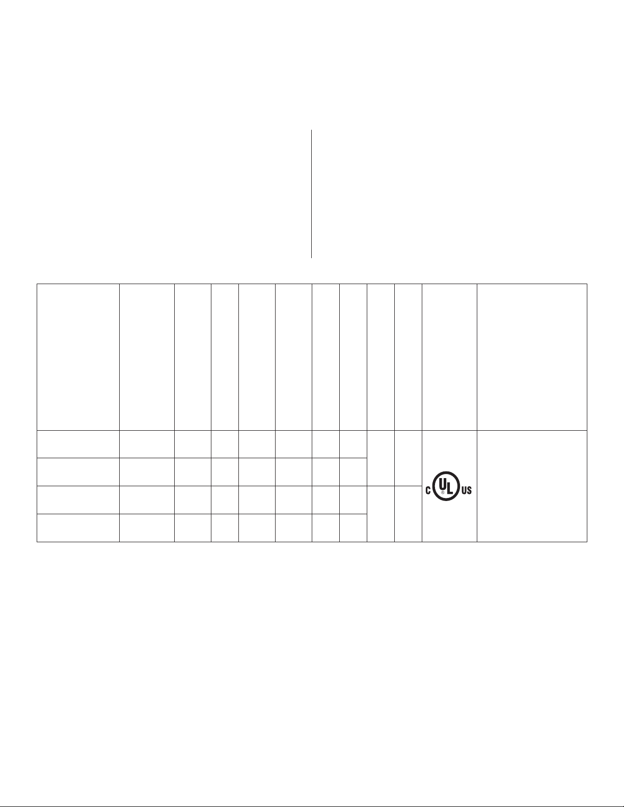
Twenty-four (24) Output Rack Mount Configuration Reference Chart:
Altronix
Model Number
Vertiline24C
Vertiline24CD
Vertiline246C
Vertiline246CD
Output Voltage (VAC)
24VAC or
28VAC
24VAC or
28VAC
24VAC or
28VAC
24VAC or
28VAC
Total Output
Current (Power)
10A 24
10A 24
14A 24
14A 24
Number of Outputs
Output Protection
Class 2 Rated Power-
Limited Output protection
Fused -- 3A 3A
-- PTC 2.5A --
Fused -- 3A 3A
-- PTC 2.5A --
Current (max. per output)
Fuse Rating
Main Fuse Rating
10A 3A
15A 4A
Agency
115VAC 60Hz Input Current
Listings
UL Listings and
File Numbers
UL Listed for
Commercial
CCTV Equipment
(UL 2044).
CUL Listed - CSA
Standard
C22.2 No.1-04,
Audio, Video and
Similar Equipment.
WARNING: To reduce the risk of fire or electric shock, do not expose the unit to rain or moisture. This
installation should be made by qualified service personnel and should conform to the National Electrical
Code and all local codes.
Installation Instructions:
1. Attach mounting brackets to Vertiline unit for rack or wall mount installation (Figs. 4-5, pg. 7). Affix rubber pads to
Vertiline for shelf installation (Fig. 6, pg. 7).
2. Secure the unit in a rack, mount unit to a wall or place unit on a shelf as desired (unit should be spaced at least 3”
from any video monitors). When installing the unit in a rack, allow for one half of a U spacing above the unit
for ventilation.
3. Plug the grounded AC line cord (included) into the IEC 320 connector of the Vertiline unit (Fig. 1f, pg. 4).
Insert the plug end of the line cord into a grounded AC receptacle.
4. Set illuminated master power disconnect circuit breaker to the (ON) position (Fig. 3, pg. 6).
5. Select 24VAC or 28VAC power output for cameras 1-24 with the corresponding voltage adjustment switches
(Fig. 1b, pg. 4).
- 2 - Vertiline24C

6. Measure output voltage before connecting cameras. This helps avoiding potential damage.
All terminals with common suffix (P) “1P, 2P ...” are the same polarity.
7. Set illuminated master power disconnect circuit breaker to the (OFF) position (Fig. 3, pg. 6).
8. Connect the power outputs of terminals marked [1P & 1N] to the power inputs of camera 1 (Fig. 2, pg. 5).
Repeat this step for each additional camera (Outputs 2-24). After the wiring is completed, insert terminal block into
the corresponding connector and secure by tightening the screws.
9. Upon completion of the wiring, set illuminated master power disconnect circuit breaker to the
ON (RESET) position (Fig. 3, pg. 6).
10. The power LEDs (Green) on the faceplate for Outputs 1-24 will illuminate when AC power is present
(Fig. 1a, pg. 4). If any of these LEDs are off, a loss of AC power output may be due to a blown fuse or a tripped
PTC caused by a short circuit or overload condition. If all of the LEDs are OFF, there may be a complete loss of
supply power to the Vertiline unit or the illuminated master power disconnect circuit breaker is in the OFF position
or the main fuse 1-12 or 13-24 is blown (Fig. 1c, pg. 4).*
To restore the power output for Vertiline24C or Vertiline246C:
1- Switch corresponding output voltage switch to the OFF position (Fig. 1b, pg. 4).
2- Eliminate the trouble condition.
3- Replace the corresponding automotive blade fuse.*
4- Switch output voltage switch to the 24VAC or 28VAC position as desired (Fig. 1b, pg. 4).
To restore the power output for Vertiline24CD or Vertiline246CD:
1- Switch corresponding output voltage switch to the OFF position (Fig. 1b, pg. 4).
2- Eliminate the trouble condition.
3- Allow 1 minute for PTC to cool off.
4- Switch output voltage switch to the 24VAC or 28VAC position as desired (Fig. 1b, pg. 4).
*Note: Replace fuses with same type and rating:
Output fuses are rated @ 3A for all models.
Main fuse ratings:
10A for Vertiline24C and Vertiline24CD.
15A for Vertiline246C and Vertiline246CD.
Automotive
Blade Fuse
Vertiline24C - 3 -
 Loading...