

Page 1
VB Series - Power Boosters
Overview:
The unit converts a 12VDC-24VDC input into a regualted 24VDC ouput.
Model Number
Altronix
Output
Input
Terminal Block
Cable Assembly
VB1 24VDC @ .75 amp 12VDC - 24VDC x -
VB1T 24VDC @ .75 amp 12VDC - 24VDC - x
Specifications:
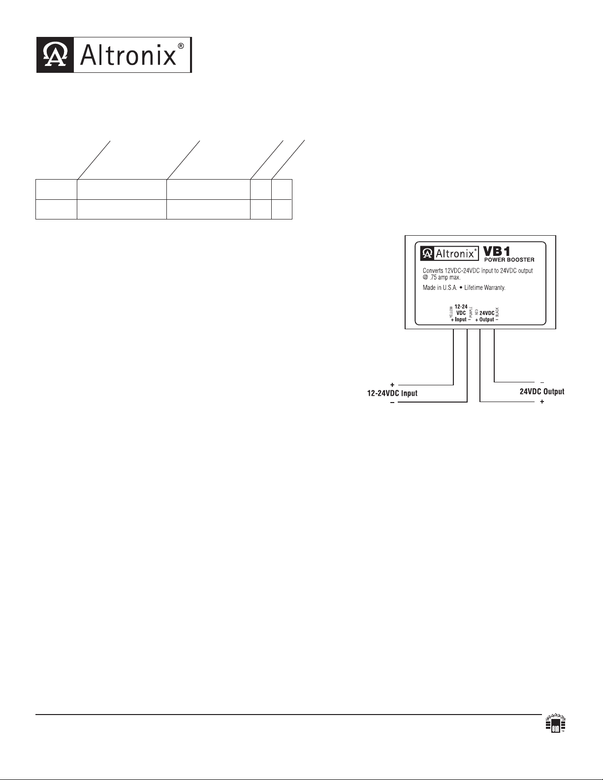
• Converts a 12VDC-24VDC input into a
regualted 24VDC ouput (
Fig. 1).
Fig. 1
• Built-in overload protection.
• Electronically filtered and regulated output.
• Power LED.
• High impact insulated housing.
• Compact design allows for integration in a wide
range of camera housings.
Dimensions: 1.625"L x 2.375"W x 1"H
Applications:
• Compensates for voltage drop due to long wire runs.
• Power for 24VDC Access Control de
vices from
a 12VDC power source.
Installation Instructions:
1. Mount the unit in desired location.
2. a. VB1: Connect Yellow (positive) lead and Purple (negative) lead to 12VDC to 24VDC source! Observe polarity.
b. VB1T : Connect 12VDC to 24VDC power source to terminals marked [IN+] and [IN--].
Measure output v
3.
oltage and check polarity before connecting de
4. a. VB1: Connect Red lead [Pos. +] and Black lead [Neg. --- ] to 24VDC device to be powered.
b. VB1T : Connect 24VDC device to be powered to terminals marked [+ OUT -- ].
5. LED will illuminate when power is present.
Note: If input voltage exceeds 24VDC output voltage will follow the input.
This may cause damage to powered equipment.
vices, in order to avoid potential damage.
Altronix is not responsible for any typographical errors. Product specifications are subject to change without notice.
140 58th Street, Brooklyn, New York 11220 USA, 718-567-8181, fax: 718-567-9056
eb site: www
w
IIVB series - Rev. 051905 J12G
.altronix.com, e-mail: info@altronix.com, Lifetime
Warranty, Made in U.S.A.
MEMBER
 Loading...