

Page 1

Access & Power Integration
Trove2SH2
- Trove2 enclosure with Altronix/Software House backplane (TSH2)
TSH2
- Altronix/Software House backplane only
Trove3SH3
- Trove3 enclosure with Altronix/Software House backplane (TSH3)
TSH3
- Altronix/Software House backplane only
Installation Guide
All registered trademarks are property of their respective owners. More than just power.™
Rev. TSH012918
Installing Company: _____________________ Service Rep. Name: __________________________________________
Address: ________________________________________________________ Phone #: _________________________
Page 2
Overview:
Edge of
Enclosure
to Access Control Panel
or U.L. Listed
Reporting Device
Enclosure
Honeywell
model # 112
Tamper Switch
or equivalent
(provided)
Trove2SH2 and Trove3SH3 accommodate various combinations of Software House boards with or without Altronix power supplies and
accessories for access systems.
Specifications:
Trove2SH2
- Trove2 enclosure with TSH2
Altronix/Software House backplane.
• Includes: tamper switch, cam lock, lock nuts and
mounting hardware.
• 16 Gauge grey enclosure with ample knockouts for
convenient access.
Enclosure Dimensions (H x W x D):
27.25” x 21.75” x 6.5” (692.2mm x 552.5mm x 165.1mm).
Accommodates up to four (4) 12VDC/7AH batteries.
TSH2
- TSH2 Altronix/Software House backplane.
• 16 Gauge backplane.
• Includes mounting hardware.
Dimensions (H x W x D):
25.375” x 19.375” x 0.3125” (644.6mm x 492.1mm x 7.9mm).
Trove3SH3
- Trove3 enclosure with TSH3
Altronix/Software House backplane.
• Includes: two (2) tamper switches, cam lock, lock nuts and
mounting hardware.
• 16 Gauge grey enclosure with ample knockouts for
convenient access.
Enclosure Dimensions (H x W x D):
36.12” x 30.125” x 7.06” (917.5mm x 768.1mm x 179.3mm).
Accommodates up to four (4) 12VDC/12AH batteries.
TSH3
- TSH3 Altronix/Software House backplane.
• 16 Gauge backplane.
• Includes mounting hardware.
Dimensions (H x W x D):
34” x 28” x 0.3125” (863.6mm x 711.2mm x 7.9mm).
Accessories:
• RSB2 - Rocker Switch Bracket for switching main power ON and OFF.
• BL6 - 68” pair of battery leads.
Backplanes Accommodate a Combination of the Following:
TSH2:
• Up to three (3) AL400ULXB2, AL600ULXB, AL1012ULXB, AL1024ULXB2, eFlow4NB, eFlow6NB, eFlow102NB, or eFlow104NB.
• Up to five (5) ACM8(CB).
• Up to two (2) ACM4(CB), MOM5, PD4UL(CB), PD8UL(CB), PDS8(CB), or VR6.
• One (1) iStar Ultra GCM or one (1) iStar Pro GCM and two (2) iStar Ultra ACM or two (2) iStar ACM SE/PRO ACM.
• One (1) I8, R8, or I8-CSI expansion modules.
TSH3:
• Up to four (4) AL400ULXB2, AL600ULXB, AL1012ULXB, AL1024ULXB2, eFlow4NB, eFlow6NB, eFlow102NB, or eFlow104NB.
• Up to four (4) ACM8(CB).
• Up to five (5) ACM4(CB), MOM5, PD4UL(CB), PD8UL(CB), PDS8(CB), or VR6.
• One (1) iStar Ultra GCM or one (1) iStar Pro GCM and two (2) iStar Ultra ACM or two (2) iStar ACM SE/PRO ACM.
• Up to two (2) I8, R8, or I8-CSI expansion modules.
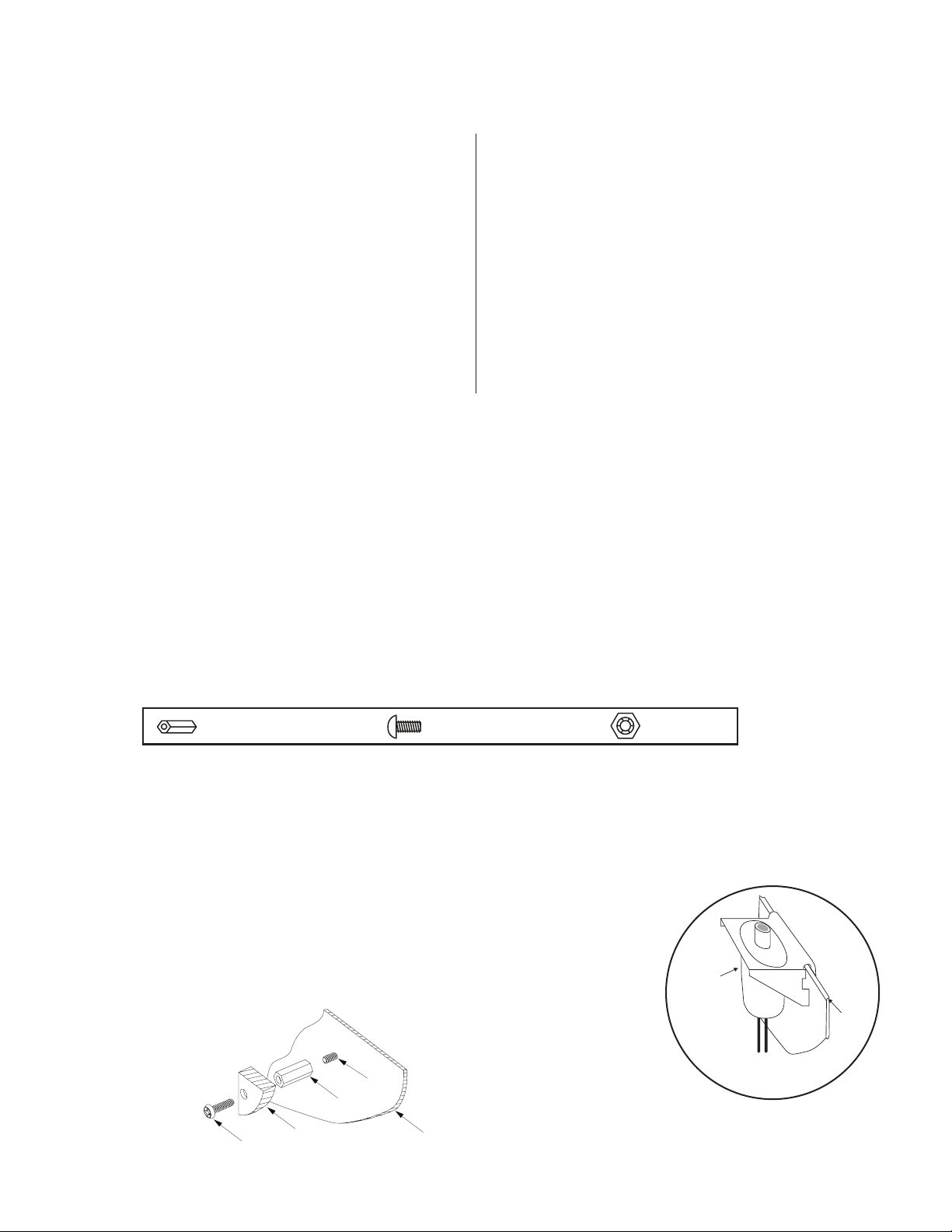
Hardware:
Metal or Nylon Standoff | 5/16” Pan Head Screw | Lock Nut
Installation Instructions:
Wiring methods shall be in accordance with the National Electrical Code/NFPA 70/ANSI, and with all local codes and authorities having
jurisdiction. Product is intended for indoor use only.
1. Remove backplane from enclosure. Do not discard hardware.
2. Mark and predrill holes in the wall to line up with the top three keyholes in the enclosure. Install three upper fasteners and screws
in the wall with the screw heads protruding. Place the enclosure’s upper keyholes over the three upper screws; level and secure.
Mark the position of the lower three holes. Remove the enclosure. Drill the lower holes and install
the three fasteners. Place the enclosure’s upper keyholes over the three upper screws.
Install the three lower screws and make sure to tighten all screws.
3. Mount included UL Listed tamper switch (Honeywell Model 112 or equivalent)
Fig. 1
in desired location, opposite hinge. Slide the tamper switch bracket onto the edge of the
enclosure approximately 2” from the right side (Fig. 1, pg. 2). Connect tamper switch
wiring to the Access Control Panel input or the appropriate UL Listed reporting device.
To activate alarm signal open the door of the enclosure.
4. Mount Altronix/Software House boards to backplane, refer to pages 3-8.
Board Mounting:
Pem
- 2 - TroveSH
Pan Head
Screw
Standoff
Power Supply or
Sub-Assembly
Backplane
Page 3
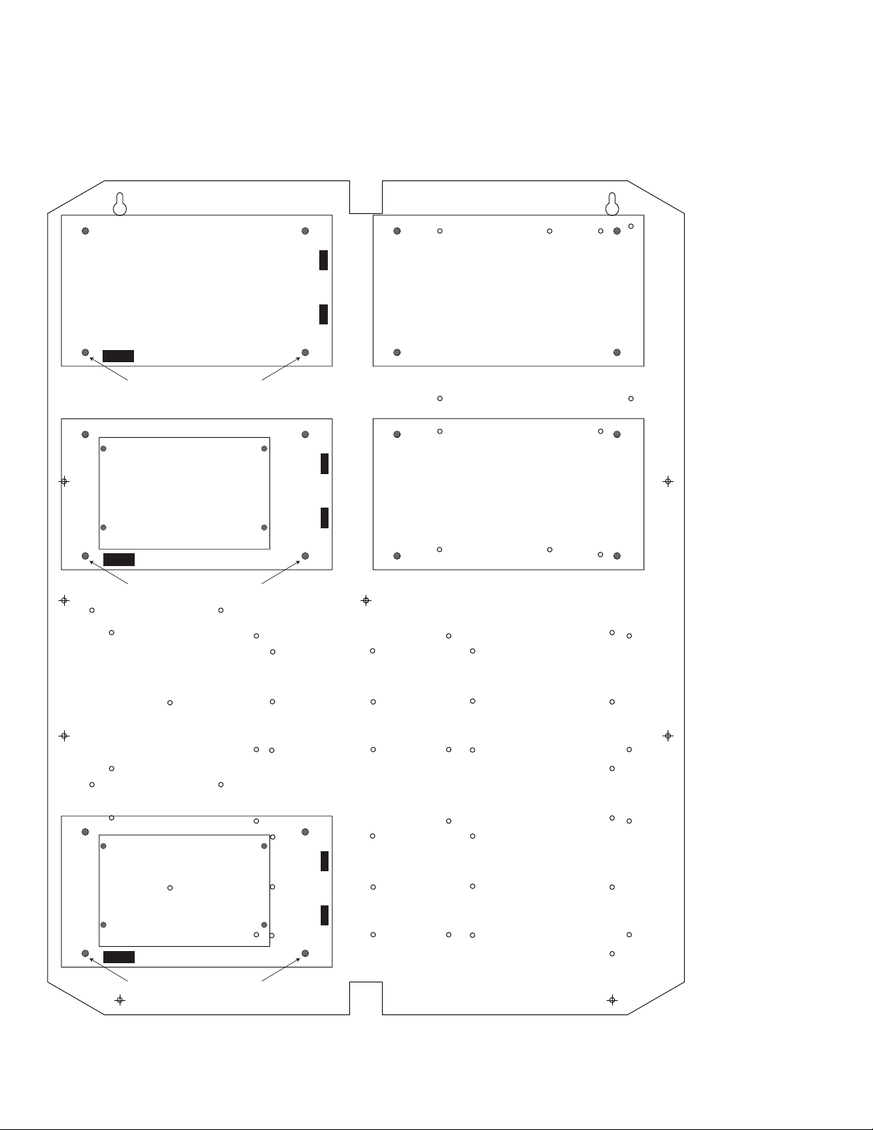
TSH2: Configuration of Altronix Power Supply and/or Sub-Assembly Boards
1. Fasten standoffs (provided) to pems that match the hole pattern for Altronix Power Supply/Chargers or Altronix Sub-Assembly boards
(Fig. 2, pg. 2).
Fasten metal standoffs in the correct locations to provide proper grounding, see below (Fig. 2, pg. 3).
2. Mount boards to standoffs utilizing 5/16” pan head screws (provided) (Fig. 2, pg. 3).
3. Fasten backplane to Trove2 enclosure utilizing lock nuts (provided).
Fig. 2
Altronix
Power Supply
Metal Standoff Placement
Altronix
Power Supply or
Sub-Assembly
Metal Standoff Placement
Altronix
Sub-Assembly
Altronix
Sub-Assembly
Altronix
Power Supply or
Sub-Assembly
Metal Standoff Placement
TroveSH - 3 -
Page 4
TSH2: Configuration of Software House iSTAR Ultra Boards
1. Align the Software House boards on the backplane to match the boards’ mounting holes with corresponding pems.
2. Fasten provided standoffs to pems that match the hole pattern for Software House iSTAR Ultra GCM and iSTAR Ultra ACM boards.
3. Mount Software House boards to standoffs utilizing 5/16” pan head screws (provided) (Fig. 3, pg. 4).
Note: Software House iSTAR Ultra ACM boards have one (1) USB port each.
Please orient boards in the appropriate position according to the Fig. 3 below.
4. Fasten backplane to Trove2 enclosure utilizing lock nuts (provided).
Fig. 3
iSTAR
Ultra GCM
iSTAR Ultra ACM
USB PORT
iSTAR Ultra ACM
USB PORT
- 4 - TroveSH
Page 5

TSH2: Configuration of Software House iSTAR Pro Boards
1. Align the Software House boards on the backplane to match the boards’ mounting holes with corresponding pems.
2. Fasten provided standoffs to pems that match the hole pattern for Software House iSTAR Pro GCM, iSTAR ACM SE/PRO ACM,
and /or I8, R8, I8-CSI boards.
3. Mount Software House boards to standoffs utilizing 5/16” pan head screws (provided) (Fig. 4, pg. 5).
Note: Software House iSTAR ACM SE/PRO ACM boards have one (1) USB port each.
Please orient boards in the appropriate position according to the Fig. 4 below.
4. Fasten backplane to Trove2 enclosure utilizing lock nuts (provided).
Fig. 4
iSTAR
Pro GCM
I8, R8 or
I8-CSI
Module
USB PORT
iSTAR
ACM SE/PRO ACM
USB PORT
iSTAR
ACM SE/PRO ACM
TroveSH - 5 -
Page 6

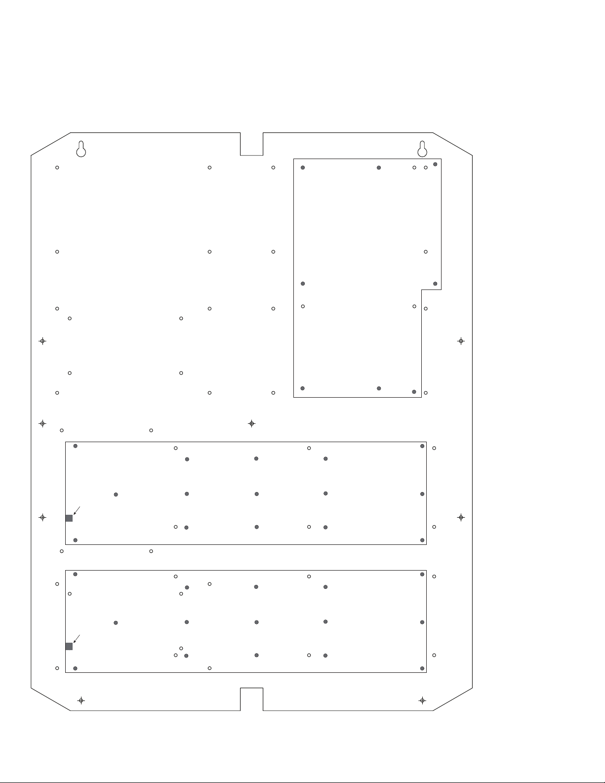
TSH3: Configuration of Altronix Power Supply and/or Sub-Assembly Boards
1. Fasten standoffs (provided) to pems that match the hole pattern for Altronix Power Supply/Chargers or Altronix Sub-Assembly boards
(Fig. 5, pg. 6).
Fasten metal standoffs in the correct locations to provide proper grounding, see below (Fig. 5, pg. 6).
2. Mount boards to standoffs utilizing 5/16” pan head screws (provided) (Fig. 5, pg. 6).
3. Fasten backplane to Trove3 enclosure utilizing lock nuts (provided).
Fig. 5
Altronix
Power Supply
Metal Standoff Placement
Altronix
Power Supply or
Sub-Assembly
Metal Standoff Placement
Altronix
Power Supply or
Sub-Assembly
Metal Standoff Placement
Altronix
Power Supply or
Sub-Assembly
Metal Standoff Placement
Altronix
Sub-Assembly
Altronix
Sub-Assembly
- 6 - TroveSH
Page 7

TSH3: Configuration of Software House iSTAR Ultra Boards
1. Align the Software House boards on the backplane to match the boards’ mounting holes with corresponding pems.
2. Fasten provided standoffs to pems that match the hole pattern for Software House iSTAR Ultra GCM and iSTAR Ultra ACM boards.
3. Mount Software House boards to standoffs utilizing 5/16” pan head screws (provided) (Fig. 6, pg. 7).
Note: Software House iSTAR Ultra ACM boards have one (1) USB port each.
Please orient boards in the appropriate position according to the Fig. 6 below.
4. Fasten backplane to Trove3 enclosure utilizing lock nuts (provided).
Fig. 6
Software House
iSTAR Ultra GCM
USB PORT
USB PORT
Software House
I8, R8 or I8-CSI
Module
Software House
iSTAR Ultra ACM
Software House
iSTAR Ultra ACM
Software House
I8, R8 or I8-CSI
Module
TroveSH - 7 -
Page 8

TSH3: Configuration of Software House iSTAR Pro Boards
1. Align the Software House boards on the backplane to match the boards’ mounting holes with corresponding pems.
2. Fasten provided standoffs to pems that match the hole pattern for Software House iSTAR Pro GCM, iSTAR ACM SE/PRO ACM,
and /or I8, R8, I8-CSI boards.
3. Mount Software House boards to standoffs utilizing 5/16” pan head screws (provided) (Fig. 7, pg. 8).
Note: Software House iSTAR Ultra ACM boards have one (1) USB port each.
Please orient boards in the appropriate position according to the Fig. 7 below.
4. Fasten backplane to Trove3 enclosure utilizing lock nuts (provided).
Fig. 6
Software House
iSTAR
Pro GCM
USB PORT
USB PORT
Software House
I8, R8 or I8-CSI
Module
Software House
iSTAR
ACM SE/PRO ACM
Software House
iSTAR
ACM SE/PRO ACM
Software House
I8, R8 or I8-CSI
Module
- 8 - TroveSH
Page 9

(
)
(
)
0.45”
(11.4mm)
TSH2 Dimensions (H x W x D):
25.375” x 19.375” x 0.3125” (644.6mm x 492.1mm x 7.9mm)
19.375”
(492.1mm)
2.2”
(55.9mm)
2.2”
(55.9mm)
0.156”
( 3.96mm)
25.375”
(644.6mm)
(11.4mm)
0.45”
9.2”
233.7mm
1.0” (25.4mm)
7.5”
(190.5mm)
16.25”
(412.8mm)
12.625”
(320.7mm)
8.5”
(215.9mm)
1.0” (25.4mm)
7.5”
(190.5mm)
9.2”
233.7mm
TroveSH - 9 -
Page 10

1.25”
(
)
(
)
(
)
(
)
(
)
(31.75mm)
Trove2 Enclosure Dimensions (H x W x D approximate):
27.25” x 21.75” x 6.5” (692.2mm x 552.5mm x 165.1mm)
21.50”
(546.1mm)
2.00”
(50.8mm)
5.25”
(133.35mm)
3.50”
(88.9mm)
0.5625”
(14.29mm)
3.50”
(88.9mm)
(44.96mm)
2.415”
(61.34mm)
1.77”
5.25”
(133.35mm)
0.685”
(17.399mm)
Knockouts
1.125” (28.32mm)
0.885” (22.479mm)
6.25”
(158.75mm)
6.25”
(158.75mm)
1.25”
(31.75mm)
G
0.85”
(21.59mm)
1.5”
(38.1mm)
27.00”
(685.8mm)
19.80”
(502.92mm)
2.00”
(50.8mm)
6.75”
(171.45mm)
8.25”
(209.54mm)
(203.2mm)
0.85”
(21.59mm)
(50.8mm)
1.00”
(25.4mm)
1.25”
(31.75mm)
2.00”
50.8mm
- 10 - TroveSH
5.25”
133.35mm
7.00”
177.79mm
5.25”
133.35mm
2.00”
50.8mm
1.25”
(31.75mm)
8.00”
2.00”
Page 11

TSH3 Dimensions (H x W x D):
34” x 28” x 0.3125” (863.6mm x 711.2mm x 7.9mm)
0.45”
(11.4mm)
2.5”
(63.5mm)
28”
(711.2mm)
0.156”
( 3.96mm)
34”
(863.6mm)
(50.8mm)
25”
(635mm)
13.5”
(342.9mm)
2”
1.0” (25.4mm)
13.5”
(342.9mm)
1.0” (25.4mm)
13.5”
(342.9mm)
TroveSH - 11 -
Page 12

Trove3 Enclosure Dimensions (H x W x D approximate):
(50.8mm)
(222.3mm)
(222.3mm)
(219mm)
2.00”
7.12”
9.5”
9.5”
(273.1mm)
(273.1mm)
(269.8mm)
(917.5mm)
36.12” x 30.125” x 7.06” (917.5mm x 768.1mm x 179.3mm)
2.00”
(50.8mm)
10.75”
10.62”
1.25”
(31.8mm)
G
G
1.25”
(31.75mm)
1.10”
(27.9mm)
(50.8mm)
1.07”
(27.2mm)
33.63”
(854.20mm)
(222.25mm)
14.01”
(355.9mm)
(241.3mm)
30.12”
(768.1mm)
(241.3mm)
(45.21mm)
14.01”
(355.9mm)
1.78”
1.55”
(39.37mm)
2.00”
(50.8mm)
10.75”
(273.1mm)
10.62”
(269.8mm)
36.12”
10.75”
1.25”
(31.8mm)
2.00”
8.75”
8.62”
8.75”
7.06”
(179.3mm)
10.75”
(273.1mm)
1.25”
(31.8mm)
Altronix is not responsible for any typographical errors.
140 58th Street, Brooklyn, New York 11220 USA | phone: 718-567-8181 | fax: 718-567-9056
web site: www.altronix.com | e-mail: info@altronix.com | Made in U.S.A.
IITroveSH I10R
- 12 - TroveSH
MEMBER
 Loading...