

Page 1

SIGNALING
Access & Power Integration
Trove1M1
- Trove1 enclosure with Altronix/Lenel backplane (TM1)
TM1
- Altronix/Lenel backplane only
Trove2M2
- Trove2 enclosure with Altronix/Lenel backplane (TM2)
TM2
- Altronix/Lenel backplane only
TMV2
- Altronix/Lenel Door Backplane. Fits Trove2 and Trove3 enclosures
Trove3M3 (not evaluated by UL)
- Trove3 enclosure with Altronix/Lenel backplane (TM3)
TM3 (not evaluated by UL)
- Altronix/Lenel backplane only
Installation Guide
All registered trademarks are property of their respective owners. More than just power.™
Rev. TMERC101817
Installing Company: _____________________ Service Rep. Name: __________________________________________
Address: ________________________________________________________ Phone #: _________________________
Page 2

Overview:
Altronix Trove1M1, Trove2M2 and Trove3M3 accommodate various combinations of Lenel boards with or without Altronix power supplies and
sub-assemblies for access systems.
Specifications:
Trove1M1
Trove1 enclosure with TM1 Altronix/Lenel backplane.
• 16 Gauge grey enclosure with ample knockouts for convenient access.
• Includes: tamper switch, cam lock, lock nuts and mounting hardware.
Enclosure Dimensions (H x W x D): 18” x 14.5” x 4.625” (457mm x 368mm x 118mm).
TM1
Altronix/Lenel backplane.
• 16 Gauge backplane.
• Includes mounting hardware.
Dimensions (H x W x D): 16.625” x 12.5” x 0.3125” (422.3mm x 317.5mm x 7.9mm).
See TM1 Sub-Assembly Position Chart on Pg. 3 for the list of compatible sub-assemblies.
Trove2M2
Trove2 enclosure with TM2 Altronix/Lenel backplane.
• 16 Gauge grey enclosure with ample knockouts for convenient access.
• Includes: tamper switch, cam lock, lock nuts and mounting hardware.
Enclosure Dimensions (H x W x D): 27.25” x 21.75” x 6.5” (692.2mm x 552.5mm x 165.1mm).
TM2
Altronix/Lenel backplane only.
• 16 Gauge backplane.
• Includes: lock nuts and mounting hardware.
Dimensions (H x W x D): 25.375” x 19.375” x 0.3125” (644.5mm x 492.1mm x 7.9mm).
See TM2 Sub-Assembly Position Charts on Pgs. 5, 7, 8 for the list of compatible sub-assemblies.
TMV2 - Optional Door Backplane
• Fits Altronix Trove2 enclosure.
Dimensions (H x W x D): 23.75” x 18.125” x 0.3125” (603.3mm x 460.4mm x 7.9mm).
See TMV2 Sub-Assembly Position Chart on Pg. 9 for the list of compatible sub-assemblies.
Trove3M3
Trove3 enclosure with TM3 Altronix/Lenel backplane.
• 16 Gauge grey enclosure with ample knockouts for convenient access.
• Includes: two (2) tamper switches, cam lock, lock nuts and mounting hardware.
Enclosure Dimensions (H x W x D): 36.12” x 30.125” x 7.06” (917.5mm x 768.1mm x 179.3mm).
TM3
Altronix/Lenel backplane only.
• 16 Gauge backplane.
• Includes: lock nuts and mounting hardware.
Dimensions (H x W x D): 34” x 28” x 0.3125” (863.6mm x 711.2mm x 7.9mm).
See TM3 Sub-Assembly Position Charts on Pgs. 10, 12 for the list of compatible sub-assemblies.
Agency Listings (When Using Altronix and Lenel Sub-Assemblies)*:
• UL 294 - 6th edition. Trove1M and Trove2M Power Controllers: Line Security I, Destructive Attack I, Endurance IV, Stand-by Power II*.
*Stand-by Power Level I if no battery is supplied.
• This Class B digital apparatus complies with Canadian ICES-003.
Cet appareil numérique de la classe B est conforme á la norme NMB-003 du Canada.
*Trove3M3 and TM3 are not evaluated by UL.
Environmental:
• Humidity and Temperature conditions as tested by UL (85%, +/-5% @ 30ºC +/-2ºC), ULC (93%, +/-2% @ 32ºC +/-2ºC).
Battery Backup:
• Trove1 enclosure accommodates up to two (2) 12VDC/7AH batteries.
• Trove2 enclosure accommodates up to two (2) 12VDC/12AH batteries.
• Trove3 enclosure accommodates up to four (4) 12VDC/12AH batteries.
For more detailed information refer to Trove Installation Guide, Rev. 101817.
Hardware:
Snap On Standoff | Standoff (Metal or Nylon) | 5/16” Pan Head Screw | 7/8” Pan Head Screw | Lock Nut
- 2 - Trove / Lenel
Page 3
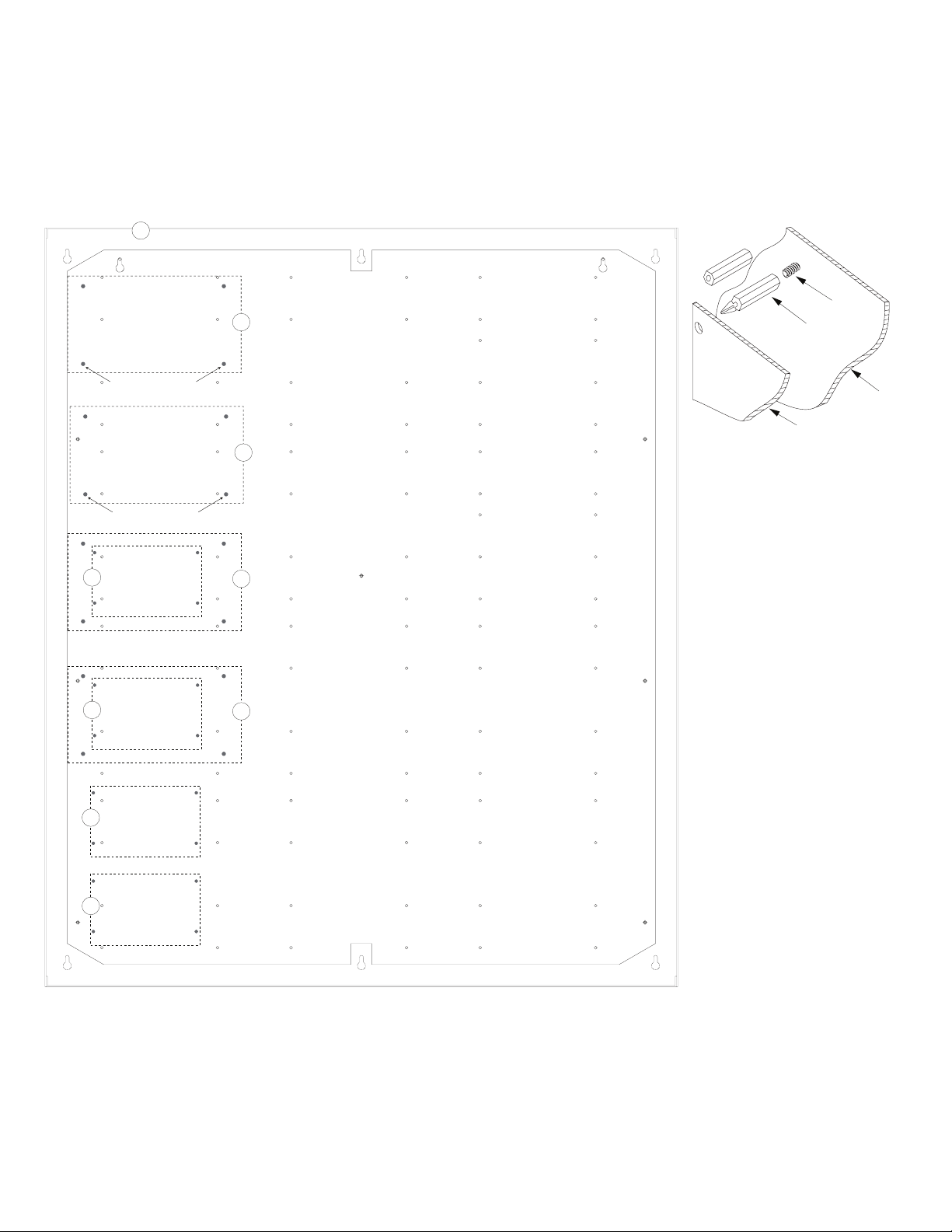
Installation Instructions for Trove1, Trove2, Trove3:
Edge of
Enclosure
to Access Control Panel
or U.L. Listed
Reportin
g
Device
Enclosure
Honeywell
model # 112
Tamper Switch
or equivalent
(provided)
Wiring methods shall be in accordance with the National Electrical Code/NFPA 70/ANSI, and with all local codes and authorities having jurisdiction.
Product is intended for indoor use only.
1. Remove backplane from enclosure. Do not discard hardware.
Fig. 1
2. Mark and predrill holes in the wall to line up with the top three keyholes in the enclosure.
Install two/three upper fasteners and screws in the wall with the screw heads protruding.
Place the enclosure’s upper keyholes over the two/three upper screws, level and secure.
Mark the position of the lower two/three holes. Remove the enclosure. Drill the lower holes
and install the two/three fasteners. Place the enclosure’s upper keyholes over the two/three
upper screws. Install the two/three lower screws and make sure to tighten all screws.
3. Mount included UL Listed tamper switch (Honeywell Model 112 or equivalent) in desired
location, opposite hinge. Slide the tamper switch bracket onto the edge of the enclosure
approximately 2” from the right side (Fig. 1, pg. 2). Connect tamper switch wiring to the
Access Control Panel input or the appropriate UL Listed reporting device.
To activate alarm signal open the door of the enclosure.
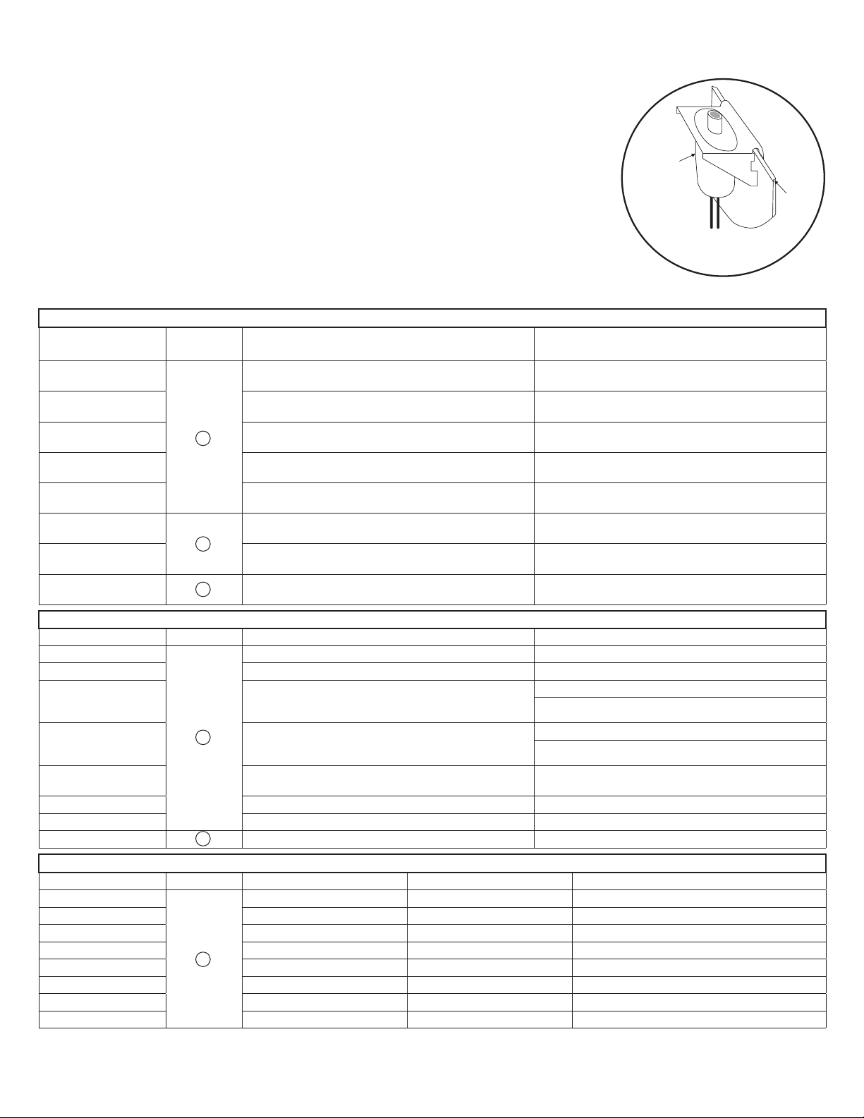
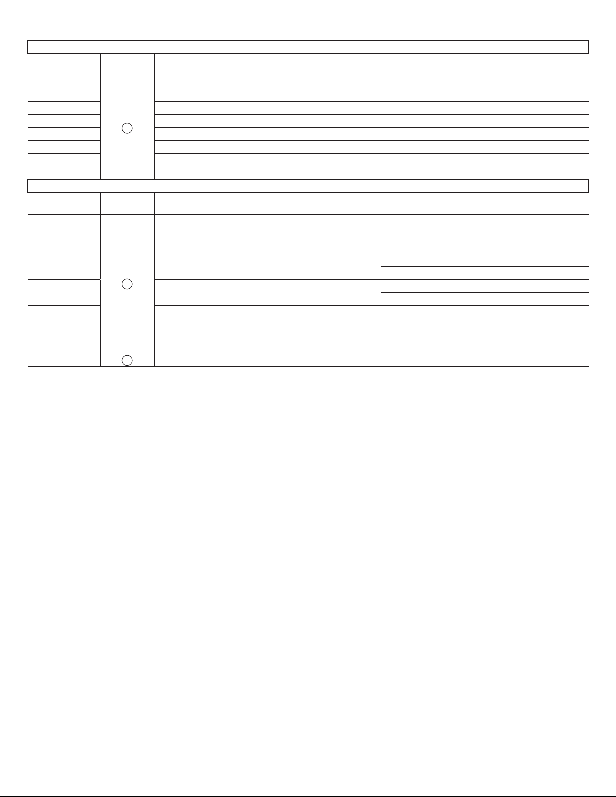
TM1 Sub-Assembly Position Chart for the Following Models:
Lenel Sub-Assemblies*
Sub-Assembly Pem Mounting Current Draw Refer to
LNL-2220
LNL-4420 12-24VDC 500mA max.
LNL-1100
LNL-1200
LNL-1320
LNL-2210
LNL-1300e 12VDC 1100mA max.
LNL-1300 E
A
D
12-24VDC 500mA max.
12-24VDC 350mA max.
(12VDC/300mA nom., 24VDC/220mA nom.)
12-24VDC 1100mA max.
(12VDC/850mA nom., 24VDC/450mA nom.)
12-24VDC 550mA max.
(12VDC/450mA nom., 24VDC/270mA nom.)
12VDC 900mA max.
12-24VDC 150mA max.
(12VDC/110mA nom., 24VDC/60mA nom.)
LNL-2220 Quick Reference
(QR50L-1002E— revision 2.022)
LNL-4420 Quick Reference
(QR50L-1024E-LNL-4420— revision 1.001)
LNL-1100 Series 2 Quick Reference
(QR50L-1010E — revision 1.019)
LNL-1200 Series 2 Quick Reference
(QR50L-1009E — revision 1.019)
LNL-1320 Series 2 Quick Reference
(QR50L-1007E — revision 1.020)
LNL-2210 Series 2 Quick Reference
(QR50L-1003E — revision 1.021)
LNL-1300e Quick Reference
(QR50L-1023E — revision 1.000)
LNL-1300 Series 2 Quick Reference
(QR50L-1008E — revision 1.020)
Altronix Sub-Assemblies
Sub-Assembly Pem Mounting Current Draw Refer to
ACM4(CB)
MOM5 12-24VDC @ 55mA max. MOM5 Installation Instructions Rev. 042811
PD4UL(CB) N/A
PD8UL(CB) N/A
PD16W(CB) N/A
PDS8(CB) N/A PDS8/PDS8CB Installation Instructions Rev. 070116
VR6 24VDC @ 1.75A or 3.5A (Output: 5VDC or 12VDC @ 6A) VR6 Installation Instructions Rev. 050517
LINQ2** F 12-24VDC @ 100mA max. LINQ2 Installation Instructions Rev. 060514
C
12VDC @ 0.4A max. or 24VDC @ 0.2A max. ACM4/ACM4CB Installation Instructions Rev. 051311
PD4UL Installation Instructions IIPD4UL Rev. 051311
PD4ULCB Installation Instructions
IIPD4ULCB Rev. 051311
PD8UL Installation Instructions IIPD8UL Rev. 051311
PD8ULCB Installation Instructions
IIPD8ULCB Rev. 051311
PD16W/PD16WCB Installation Instructions
IIPD16W Rev. 051311
Altronix Power Supplies/Sub-Assemblies
Sub-Assembly Pem Mounting Input Rating Output Rating Refer to
AL400ULXB2
AL600ULXB 115VAC, 60Hz, 3.5A 12VDC or 24VDC @ 6A ULXB Installation Instructions Rev. ULXB-10182016
AL1012ULXB 115VAC, 60Hz, 2.6A 12VDC @ 10A ULXB Installation Instructions Rev. ULXB-10182016
AL1024ULXB2 115VAC, 60Hz, 4.2A 24VDC @ 10A ULXB Installation Instructions Rev. ULXB-10182016
eFlow4NB** 120VAC, 60Hz, 3.5A 12VDC or 24VDC @ 4A eFlow Installation Instructions Rev. EFNB-10182016
eFlow6NB** 120VAC, 60Hz, 3.5A 12VDC or 24VDC @ 6A eFlow Installation Instructions Rev. EFNB-10182016
eFlow102NB** 120VAC, 60Hz, 3.5A 12VDC @ 10A eFlow Installation Instructions Rev. EFNB-10182016
eFlow104NB** 120VAC, 60Hz, 4.5A 24VDC @ 10A eFlow Installation Instructions Rev. EFNB-10182016
* For detailed information, refer to the Lenel Hardware Installation Guide, DOC-600, revision 30.034.
** LINQ2 can be installed when utilizing eFlow power supply/charger boards.
- 3 - Trove / Lenel
B
115VAC, 60Hz, 3.5A 12VDC @ 4A or 24VDC @ 3A ULXB Installation Instructions Rev. ULXB-10182016
Page 4
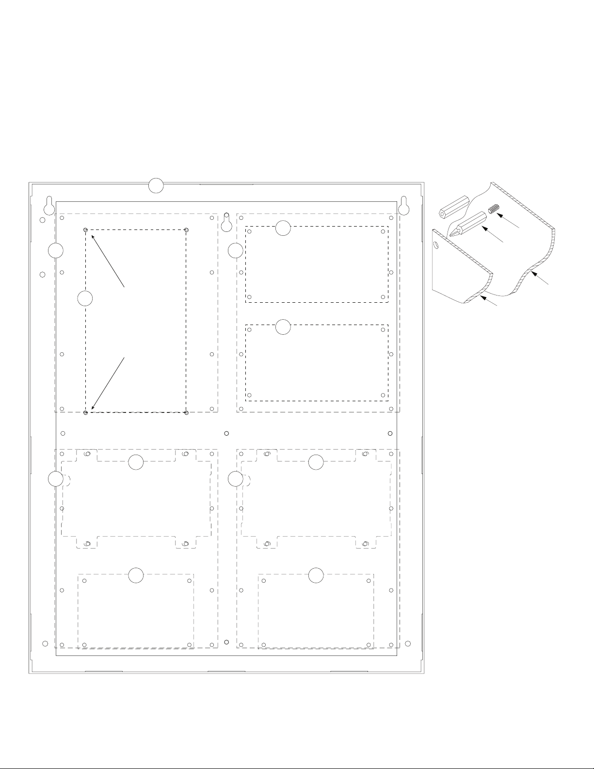
Installation Instructions for Sub-Assemblies to TM1:
Altronix Power Supplies/Chargers and/or Sub-Assemblies:
1. Fasten standoffs (provided) to pems that match the hole pattern for Altronix Power Supply/Chargers or Altronix Sub-Assembly boards
(positions (B) and (C), Fig. 2, pg. 4). Use snap on nylon standoffs for the upper two mounting holes in the board.
Use metal standoffs for the bottom mounting holes to provide sufficient grounding for the board.
2. Affix boards to standoffs (Fig. 2, pg. 4) by pressing down the upper mounting holes onto nylon standoffs.
Use provided mounting screws to affix the lower mounting holes. Make sure that boards are locked onto standoffs.
3. For detailed information about installing and connecting Altronix sub-assemblies refer to the individual Installation Instructions listed in the
Sub-Assembly Position Chart, pg. 2 and Trove Installation Guide, Rev. 101817.
Lenel Sub-Assemblies:
4. Fasten standoffs onto metal pems configuration (A), (D) or (E) of enclosure depending on the sub-assembly module (Fig. 2, pg. 4).
5. Position sub-assembly module over corresponding standoffs and secure module into enclosure with four (4) pan head screws supplied (Fig. 2, pg. 4).
6. Fasten backplane to Trove1 enclosure utilizing lock nuts (provided).
Fig. 2
A
B
F
Metal Standoff
Placement
for Altronix
Power Supplies
D
A
C
C
Fig. 2a
Pem
Snap on or
Metal
Standoff
Backplane
Sub-Assembly
D
A
E
Trove / Lenel - 4 -
A
E
Page 5

TM2 Sub-Assembly Position Chart for the Following Models:
Altronix Power Supplies/Chargers
Altronix
Pem
Mounting
AL400ULXB2
AL600ULXB 115VAC, 60Hz, 3.5A 12VDC or 24VDC @ 6A
AL1012ULXB 115VAC, 60Hz, 2.6A 12VDC @ 10A
AL1024ULXB2 115VAC, 60Hz, 4.2A 24VDC @ 10A
eFlow4NB* 120VAC, 60Hz, 3.5A 12VDC or 24VDC @ 4A
A
eFlow6NB* 120VAC, 60Hz, 3.5A 12VDC or 24VDC @ 6A
eFlow102NB* 120VAC, 60Hz, 3.5A 12VDC @ 10A
eFlow104NB* 120VAC, 60Hz, 4.5A 24VDC @ 10A
Altronix
Pem
Mounting
ACM4(CB)
ACM8(CB) 12VDC @ 0.5A max. or 24VDC @ 0.3A max.
MOM5 12-24VDC 55mA max.
PD4UL(CB) N/A
B
PD8UL(CB) N/A
PD16W(CB) N/A
PDS8(CB) N/A
VR6 24VDC @ 1.75A or 3.5A (Output: 5VDC or 12VDC @ 6A)
LINQ2* C 12-24VDC 100mA max.
* LINQ2 can be installed when utilizing eFlow power supply/charger boards.
Input Rating Output Rating
115VAC, 60Hz, 3.5A 12VDC @ 4A or 24VDC @ 3A
Altronix Sub-Assemblies
Current Draw
12VDC @ 0.4A max. or 24VDC @ 0.2A max.
Refer to
ULXB Installation Instructions Rev. ULXB-10182016
ULXB Installation Instructions Rev. ULXB-10182016
ULXB Installation Instructions Rev. ULXB-10182016
ULXB Installation Instructions Rev. ULXB-10182016
eFlow Installation Instructions Rev. EFNB-10182016
eFlow Installation Instructions Rev. EFNB-10182016
eFlow Installation Instructions Rev. EFNB-10182016
eFlow Installation Instructions Rev. EFNB-10182016
Refer to
ACM4/ACM4CB Installation Instructions Rev. 051311
ACM8/ACM8CB Installation Instructions Rev. 042811
MOM5 Installation Instructions Rev. 042811
PD4UL Installation Instructions IIPD4UL Rev. 051311
PD4ULCB Installation Instructions IIPD4ULCB Rev. 051311
PD8UL Installation Instructions IIPD8UL Rev. 051311
PD8ULCB Installation Instructions IIPD8ULCB Rev. 051311
PD16W/PD16WCB Installation Instructions
IIPD16W Rev. 051311
PDS8/PDS8CB Installation Instructions Rev. 070116
VR6 Installation Instructions Rev. 050517
LINQ2 Installation Instructions Rev. 060514
- 5 - Trove / Lenel
Page 6

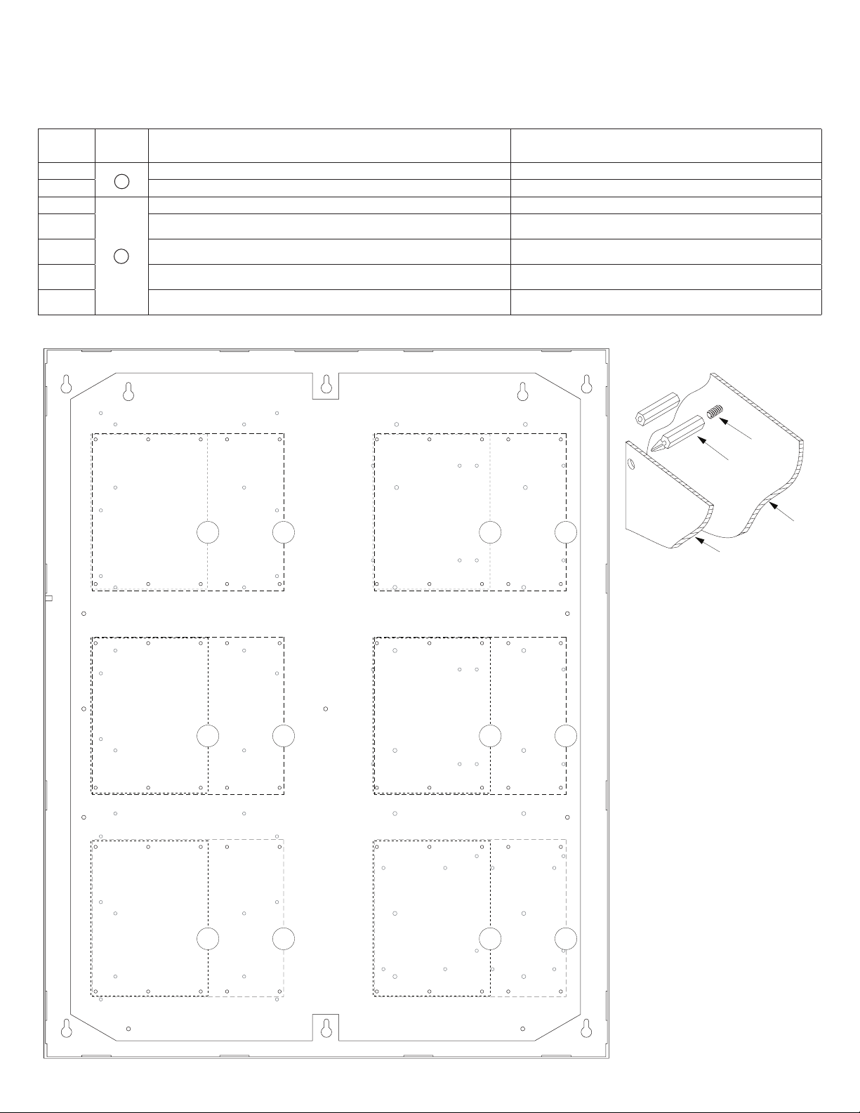
Installation Instructions for Altronix Power Supplies and/or Sub-Assemblies to TM2:
1. Fasten standoffs (provided) to pems that match the hole pattern for Altronix Power Supply/Chargers or Altronix Sub-Assembly boards (Fig. 3, pg. 6).
Use snap on nylon standoffs for the upper two mounting holes in the board.
Use metal standoffs for the bottom mounting holes to provide sufficient grounding for the board.
2. Affix boards to standoffs (Fig. 3, pg. 6) by pressing down the upper mounting holes onto nylon standoffs.
Use provided mounting screws to affix the lower mounting holes. Make sure that boards are locked onto standoffs.
3. For detailed information about installing and connecting Altronix sub-assemblies refer to the individual Installation Instructions listed in the
Sub-Assembly Position Chart, pg. 2 and Trove Installation Guide, Rev. 101817.
4. Fasten backplane to Trove2 enclosure utilizing lock nuts (provided).
Fig. 3
C
B
Metal Standoff Placement
B
Metal Standoff Placement
A
A
Fig. 3a
Pem
Snap on or
Metal
Standoff
Backplane
Sub-Assembly
B
B
A
A
Trove / Lenel - 6 -
Page 7
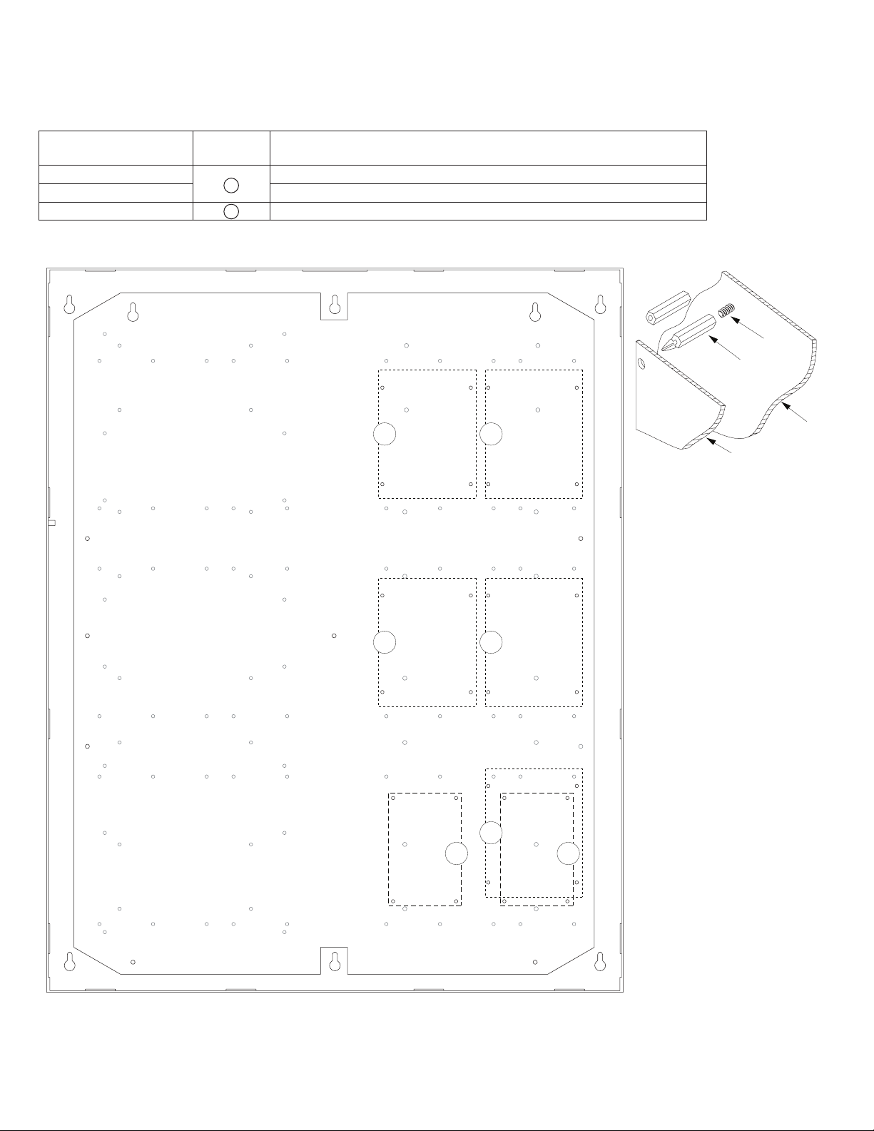
Installation Instructions for Lenel Access Controllers to TM2:
1. Fasten snap on standoffs onto metal pems configuration (A) (B) of backplane depending on the access controller (Fig. 4, pg. 7).
2. Position access controller module over corresponding standoffs and depress onto snap on standoffs (Fig. 4a, pg. 7).
3. Mount backplane to enclosure with hardware.
Access Controller Position Chart for the Following Models:
Lenel
LNL-3300
LNL-8000 12VDC 250mA max. LNL-8000 Quick Reference (QR50L-1000E — revision 1.020)
LNL-2220
LNL-4420 12-24VDC 500mA max.
LNL-1100 12-24VDC 350mA max. (12VDC @ 300mA nom., 24VDC @ 220mA nom.)
LNL-1200 12-24VDC 1100mA max. (12VDC @ 850mA nom., 24VDC @ 450mA nom.)
LNL-1320 12-24VDC 550mA max. (12VDC @ 450mA nom., 24VDC @ 270mA nom.)
Fig. 4
Pem
Mounting
A
B
Current Draw Refer to
12-24VDC 300mA max. LNL-3300 Quick Reference (QR50L-1001E — revision 2.023)
12-24VDC 500mA max. LNL-2220 Quick Reference (QR50L-1002E - revision 2.022)
LNL-4420 Quick Reference
(QR50L-1024E-LNL-4420 - revision 1.001)
LNL-1100 Series 2 Quick Reference
(QR50L-1010E - revision 1.019)
LNL-1200 Series 2 Quick Reference
(QR50L-1009E — revision 1.019)
LNL-1320 Series 2 Quick Reference
(QR50L-1007E — revision 1.020)
Fig. 4a
Pem
BA BA
BA BA
Snap on or
Metal
Standoff
Backplane
Sub-Assembly
BA BA
- 7 - Trove / Lenel
Page 8
Installation Instructions for Lenel Access Controllers to TM2:
1. Fasten snap on standoffs onto metal pems configuration (A) (B) of backplane depending on the access controller (Fig. 5, pg. 8).
2. Position access controller module over corresponding standoffs and depress onto snap on standoffs (Fig. 5a, pg. 8).
3. Mount backplane to enclosure with hardware.
Access Controller Position Chart for the Following Models:
Lenel
LNL-2210
LNL-1300e 12VDC 1100mA max.
LNL-1300 B 12-24VDC 150mA max. (12VDC @ 110mA nom., 24VDC @ 60mA nom.)
Pem
Mounting
A
Fig. 5
Current Draw
12VDC 900mA max.
Fig. 5a
Pem
Snap on or
Metal
Standoff
A A
A A
A
Backplane
Sub-Assembly
BB
Trove / Lenel - 8 -
Page 9

Installation Instructions for Lenel Access Controllers to TMV2 (Door Backplane):
1. Fasten snap on standoffs onto metal pems configuration (A) (B) of backplane depending on the access controller (Fig. 6, pg. 9).
2. Position access controller module over corresponding standoffs and depress onto snap on standoffs (Fig. 6a, pg. 9).
3. Mount backplane to enclosure with hardware.
Access Controller Position Chart for the Following Models:
Lenel
LNL-3300
LNL-8000 12VDC 250mA max.
LNL-2220
LNL-4420 12-24VDC 500mA max.
LNL-1100 12-24VDC 350mA max. (12VDC @ 300mA nom., 24VDC @ 220mA nom.)
LNL-1200 12-24VDC 1100mA max. (12VDC @ 850mA nom., 24VDC @ 450mA nom.)
LNL-1320 12-24VDC 550mA max. (12VDC @ 450mA nom., 24VDC @ 270mA nom.)
Fig. 6
Pem
Mounting
A
B
Current Draw
12-24VDC 300mA max.
12-24VDC 500mA max.
Fig. 6a
Pem
Snap on or
Metal
Standoff
BA BA
BA
Backplane
Sub-Assembly
BA
BA
- 9 - Trove / Lenel
BA
Page 10
TM3 Sub-Assembly Position Chart for the Following Models:
Altronix Power Supplies/Chargers
Altronix
Pem
Mounting
AL400ULXB2
AL600ULXB 115VAC, 60Hz, 3.5A 12VDC or 24VDC @ 6A
AL1012ULXB 115VAC, 60Hz, 2.6A 12VDC @ 10A
AL1024ULXB2 115VAC, 60Hz, 4.2A 24VDC @ 10A
eFlow4NB* 120VAC, 60Hz, 3.5A 12VDC or 24VDC @ 4A
A
eFlow6NB* 120VAC, 60Hz, 3.5A 12VDC or 24VDC @ 6A
eFlow102NB* 120VAC, 60Hz, 3.5A 12VDC @ 10A
eFlow104NB* 120VAC, 60Hz, 4.5A 24VDC @ 10A
Altronix
Pem
Mounting
ACM4(CB)
ACM8(CB) 12VDC @ 0.5A max. or 24VDC @ 0.3A max.
MOM5 12-24VDC 55mA max.
PD4UL(CB) N/A
B
PD8UL(CB) N/A
PD16W(CB) N/A
PDS8(CB) N/A
VR6 24VDC @ 1.75A or 3.5A (Output: 5VDC or 12VDC @ 6A)
LINQ2* C 12-24VDC 100mA max.
* LINQ2 can be installed when utilizing eFlow power supply/charger boards.
Input Rating Output Rating
115VAC, 60Hz, 3.5A 12VDC @ 4A or 24VDC @ 3A
Altronix Sub-Assemblies
Current Draw
12VDC @ 0.4A max. or 24VDC @ 0.2A max.
Refer to
ULXB Installation Instructions Rev. ULXB-10182016
ULXB Installation Instructions Rev. ULXB-10182016
ULXB Installation Instructions Rev. ULXB-10182016
ULXB Installation Instructions Rev. ULXB-10182016
eFlow Installation Instructions Rev. EFNB-10182016
eFlow Installation Instructions Rev. EFNB-10182016
eFlow Installation Instructions Rev. EFNB-10182016
eFlow Installation Instructions Rev. EFNB-10182016
Refer to
ACM4/ACM4CB Installation Instructions Rev. 051311
ACM8/ACM8CB Installation Instructions Rev. 042811
MOM5 Installation Instructions Rev. 042811
PD4UL Installation Instructions IIPD4UL Rev. 051311
PD4ULCB Installation Instructions IIPD4ULCB Rev. 051311
PD8UL Installation Instructions IIPD8UL Rev. 051311
PD8ULCB Installation Instructions IIPD8ULCB Rev. 051311
PD16W/PD16WCB Installation Instructions
IIPD16W Rev. 051311
PDS8/PDS8CB Installation Instructions Rev. 070116
VR6 Installation Instructions Rev. 050517
LINQ2 Installation Instructions Rev. 060514
Trove / Lenel - 10 -
Page 11
Installation Instructions for Altronix Power Supplies and/or Sub-Assemblies to TM3:
1. Fasten standoffs (provided) to pems that match the hole pattern for Altronix Power Supply/Chargers or Altronix Sub-Assembly boards (Fig. 7, pg. 11).
Use snap on nylon standoffs for the upper two mounting holes in the board.
Use metal standoffs for the bottom mounting holes to provide sufficient grounding for the board.
2. Affix boards to standoffs (Fig. 7, pg. 11) by pressing down the upper mounting holes onto nylon standoffs.
Use provided mounting screws to affix the lower mounting holes. Make sure that boards are locked onto standoffs.
3. For detailed information about installing and connecting Altronix sub-assemblies refer to the individual Installation Instructions listed in the
Sub-Assembly Position Chart, pg. 2 and Trove Installation Guide, Rev. 101817.
4. Fasten backplane to Trove3 enclosure utilizing lock nuts (provided).
Fig. 3
C
Metal Standoff Placement
A
Snap on or
Metal
Standoff
A
Fig. 7a
Pem
Backplane
Sub-Assembly
Metal Standoff Placement
B
B
B
B
A
A
Trove / Lenel - 11 -
Page 12

Installation Instructions for Lenel Access Controllers to TM3:
1. Fasten snap on standoffs onto metal pems configuration (A) (B) of backplane depending on the access controller (Fig. 8, pg. 12).
2. Position access controller module over corresponding standoffs and depress onto snap on standoffs (Fig. 8a, pg. 12).
3. Mount backplane to enclosure with hardware.
Access Controller Position Chart for the Following Models:
Lenel
LNL-3300
LNL-8000 12VDC 250mA max.
LNL-2220
LNL-4420 12-24VDC 500mA max.
LNL-1100 12-24VDC 350mA max. (12VDC @ 300mA nom., 24VDC @ 220mA nom.)
LNL-1200 12-24VDC 1100mA max. (12VDC @ 850mA nom., 24VDC @ 450mA nom.)
LNL-1320 12-24VDC 550mA max. (12VDC @ 450mA nom., 24VDC @ 270mA nom.)
Fig. 4
Pem
Mounting
A
B
Current Draw
12-24VDC 300mA max.
12-24VDC 500mA max.
Fig. 8a
B
B
B
Pem
A
A
A
Snap on or
Metal
Standoff
Backplane
Sub-Assembly
B
A
B
A
B
A
B
A
B
A
B
A
B
A
- 12 - Trove / Lenel
B
A
B
A
Page 13

Notes:
Trove / Lenel - 13 -
Page 14

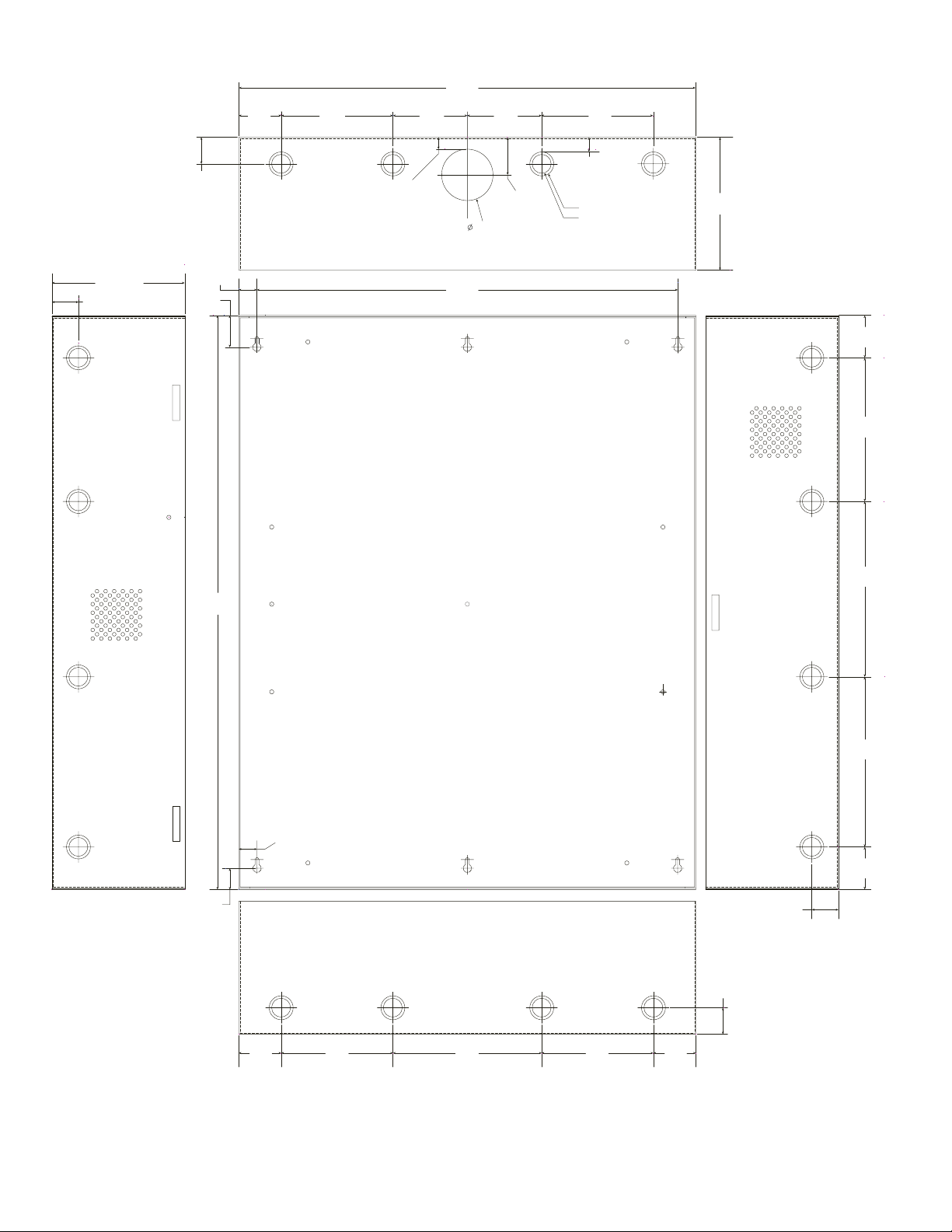
1.25”
(31.75mm)
1.5”
(38.09mm)
(114.3mm)
0.569”
(14.52mm)
4.5”
Trove1 Enclosure Dimensions (H x W x D approximate):
18” x 14.5” x 4.625” (457mm x 368mm x 118mm)
14.5”
13.0”
(330.2mm)
(368mm)
(49.483mm)
1.948”
(184.15mm)
0.5897”
(14.98mm)
7.25”
1.45”
(36.83mm)
1.25”
(31.75mm)
1.5”
(38.09mm)
8.5”
(215.9mm)
6.5”
(165.1mm)
18.0”
(457.2mm)
0.6012”
(15.27mm)
1.0958”
(27.83mm)
4.5”
(114.3mm)
4.5”
(114.3mm)
2.75”
(69.85mm)
8.5”
(215.9mm)
6.5”
(165.1mm)
1.115”
(28.32mm)
1.362”
(34.59mm)
1.25”
(31.75mm)
- 14 - Trove / Lenel
Page 15
1.25”
(
)
(
)
(
)
(
)
(
)
(31.75mm)
Trove2 Enclosure Dimensions (H x W x D approximate):
27.25” x 21.75” x 6.5” (692.2mm x 552.5mm x 165.1mm)
21.50”
(546.1mm)
2.00”
(50.8mm)
5.25”
(133.35mm)
3.50”
(88.9mm)
0.5625”
(14.29mm)
3.50”
(88.9mm)
(44.96mm)
2.415”
(61.34mm)
1.77”
5.25”
(133.35mm)
0.685”
(17.399mm)
Knockouts
1.125” (28.32mm)
0.885” (22.479mm)
6.25”
(158.75mm)
6.25”
(158.75mm)
1.25”
(31.75mm)
G
0.85”
(21.59mm)
1.5”
(38.1mm)
27.00”
(685.8mm)
19.80”
(502.92mm)
2.00”
(50.8mm)
6.75”
(171.45mm)
8.25”
(209.54mm)
8.00”
(203.2mm)
0.85”
(21.59mm)
2.00”
(50.8mm)
1.00”
(25.4mm)
1.25”
(31.75mm)
2.00”
50.8mm
Trove / Lenel - 15 -
5.25”
133.35mm
7.00”
177.79mm
5.25”
133.35mm
2.00”
50.8mm
1.25”
(31.75mm)
Page 16

Trove3 Enclosure Dimensions (H x W x D approximate):
(50.8mm)
(222.3mm)
(222.3mm)
(219mm)
2.00”
7.12”
9.5”
9.5”
(273.1mm)
(273.1mm)
(269.8mm)
(917.5mm)
36.12” x 30.125” x 7.06” (917.5mm x 768.1mm x 179.3mm)
2.00”
(50.8mm)
10.75”
10.62”
1.25”
(31.8mm)
G
G
1.25”
(31.75mm)
1.10”
(27.9mm)
(50.8mm)
1.07”
(27.2mm)
33.63”
(854.20mm)
(222.25mm)
14.01”
(355.9mm)
(241.3mm)
30.12”
(768.1mm)
(241.3mm)
(45.21mm)
14.01”
(355.9mm)
1.78”
1.55”
(39.37mm)
2.00”
(50.8mm)
10.75”
(273.1mm)
10.62”
(269.8mm)
36.12”
10.75”
1.25”
(31.8mm)
2.00”
8.75”
8.62”
8.75”
7.06”
(179.3mm)
10.75”
(273.1mm)
1.25”
(31.8mm)
Altronix is not responsible for any typographical errors.
140 58th Street, Brooklyn, New York 11220 USA | phone: 718-567-8181 | fax: 718-567-9056
web site: www.altronix.com | e-mail: info@altronix.com | Made in U.S.A.
IITrove / Lenel I10R
- 16 - Trove / Lenel
MEMBER
 Loading...