

Page 1

SIGNALING
Access & Power Integration
Trove2KA2
- Trove2 enclosure with Altronix/Keyscan backplane (TKA2)
TKA2
- Altronix/Keyscan backplane only
Trove3KA3
- Trove3 enclosure with Altronix/Keyscan backplane (TKA3)
TKA3
- Altronix/Keyscan backplane only
Installation Guide
All registered trademarks are property of their respective owners. More than just power.™
Rev. TKA042816
Installing Company: _____________________ Service Rep. Name: __________________________________________
Address: ________________________________________________________ Phone #: _________________________
Page 2
Overview:
Tamper Switch
(provided)
To Access Control Panel or
UL Listed Reporting Device
Edge of
Enclosure
Enclosure
Trove2KA2/Trove3KA3 accommodates various combinations of Keyscan boards with or without Altronix power supplies and accessories for
access systems.
Specifications:
Trove2KA2
Trove2 enclosure with TKA2 Altronix/Keyscan backplane
• Includes: tamper switch, cam lock, and mounting hardware.
Enclosure Dimensions (H x W x D):
27.25” x 21.75” x 6.5” (692.2mm x 552.5mm x 165.1mm).
TKA2
Altronix/Keyscan backplane only
• Includes mounting hardware.
Dimensions (H x W x D):
25.375” x 19.375” x 0.3125” (644.5mm x 482.6mm x 7.9mm).
TKA2 accommodates a combination of the following:
Altronix Modules:
• One (1) AL400ULXB2, AL600ULXB, AL1012ULXB,
AL1024ULXB2, eFlow4NB, eFlow6NB, eFlow102NB, or
eFlow104NB.
• One (1) T16100, ACM4(CB), ACM8(CB), MOM5, PD4UL(CB),
PD8UL(CB), PDS8(CB), VR6.
Keyscan Modules:
• One (1) CA250B, CA4500B, CA8500B, one (1) DPS-15,
one (1) CIM.
• Two (2) OCB8
Trove3KA3
Trove3 enclosure with TKA3 Altronix/Keyscan backplane
• Includes: (2) tamper switches, cam lock, and mounting hardware.
Enclosure Dimensions (H x W x D):
36.12” x 30.125” x 7.06” (917.5mm x 768.1mm x 179.3mm).
TKA3
Altronix/Keyscan backplane only
• Includes mounting hardware.
Dimensions (H x W x D):
34” x 28” x 0.3125” (863.6mm x 711.2mm x 7.9mm).
TKA3 accommodates a combination of the following:
Altronix Modules:
• One (1) AL400ULXB2, AL600ULXB, AL1012ULXB,
AL1024ULXB2, eFlow4NB, eFlow6NB, eFlow102NB, or
eFlow104NB.
• One (1) T16100, ACM4(CB), ACM8(CB), MOM5, PD4UL(CB),
PD8UL(CB), PDS8(CB), VR6.
Keyscan Modules:
• Tw o (2) CA250B, CA4500B, CA8500B, two (2) DPS-15,
two (2) CIM.
• Four (4) OCB8
Agency Listings:
• UL 294 - 6th edition: Line Security I, Destructive Attack I, Endurance IV, Stand-by Power II*.
*Stand-by Power Level I if no battery is supplied.
• This Class B digital apparatus complies with Canadian ICES-003.
Cet appareil numérique de la classe B est conforme á la norme NMB-003 du Canada.
• CE European Conformity.
Installation Instructions for Trove2/Trove3:
1. Remove backplane from enclosure prior to mounting (do not discard hardware).
2. Mark and predrill holes in the wall to line up with the top keyholes in the enclosure. Install the upper fasteners and screws in the wall
with the screw heads protruding. Place the enclosure’s upper keyholes over the screws; level and secure.
Mark the position of the lower holes. Remove the enclosure. Drill the lower holes and install the fasteners.
Place the enclosure’s upper keyholes over the upper screws. Install the lower screws and make
sure to tighten all screws (Enclosure Dimensions, pg. 6, 8).
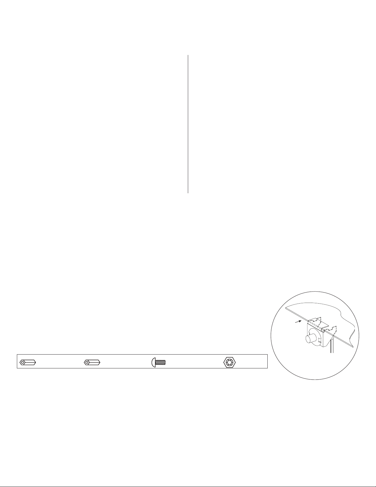
3. Mount included UL Listed tamper switch (Altronix Model TS112 or equivalent) in desired location,
opposite hinge. Slide the tamper switch bracket onto the edge of the enclosure approximately 2”
from the right side (Fig. 1, pg. 2). Connect tamper switch wiring to the Access Control Panel
input or the appropriate UL Listed reporting device.
To activate alarm signal open the door of the enclosure.
4. Mount Altronix/Keyscan boards to backplane, refer to pages 3, 4.
Fig. 1
Hardware:
Nylon Spacer | Metal Spacer | Pan Head Screw | Lock Nut
- 2 - Trove2KA2 / Trove3KA3
Page 3
TKA2: Configuration of Altronix Power Supply
and/or Sub-Assembly Boards and Keyscan Boards
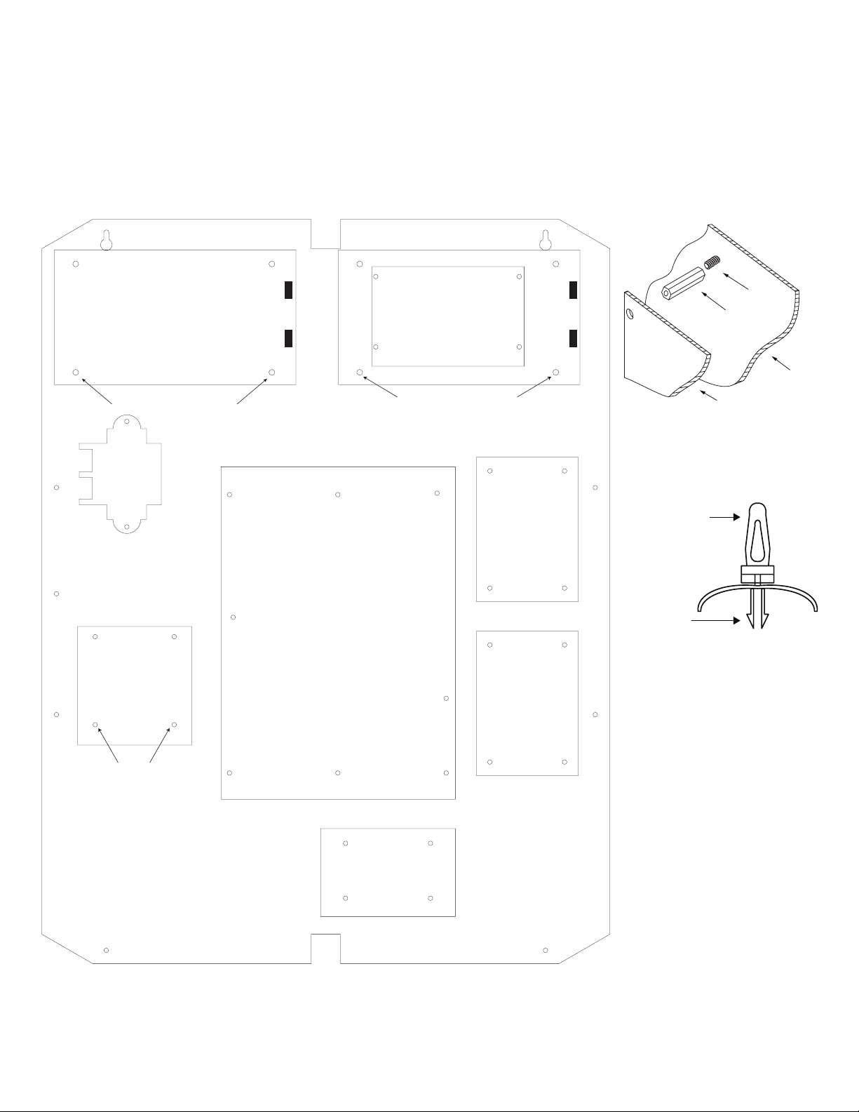
1. Fasten metal and snap on spacers (provided) to pems which match the hole pattern for Altronix Power Supply/Chargers or Altronix
Sub-Assembly boards (Fig. 2, 2a, pg. 3). Note: Please fasten metal and snap on spacers in the proper locations (Fig. 2, pg. 3).
2. Mount boards to spacers utilizing 5/16” pan head screws (provided) (Fig. 2, pg. 3).
3. Mount Altronix T16100 transformer to backplane using two locking nuts (Fig. 2, pg. 3).
4. Mount appropriate Keyscan boards into the correct positions (Fig. 2, pg. 3) by postioning spacers over appropriate holes on the
backplane and depress down on board to secure spacer to the backplane (Fig. 2b, pg. 3).
5. Fasten backplane to Trove2 enclosure utilizing pan head screws (provided).
Fig. 2
Fig. 2a
Altronix
Power Supply
Metal Spacer Placement Metal Spacer Placement
Altronix
T16100
Keyscan
CA250B,
CA4500B
CA8500B
Keyscan
DPS15
Altronix
Power Supply or
Sub-Assembly
Keyscan
OCB8
Keyscan
OCB8
Plastic Spacer
pre-mounted into
Keyscan modules
Insert into
TKA2 or
TKA3 backplane
Pem
Nylon or
Metal
Spacer
Backplane
Sub-Assembly
Fig. 2b
Locknut
Keyscan
CIM
Trove2KA2 / Trove3KA3 - 3 -
Page 4

TKA3: Configuration of Altronix Power Supply
and/or Sub-Assembly Boards and Keyscan Boards
1. Fasten metal and snap on spacers (provided) to pems which match the hole pattern for Altronix Power Supply/Chargers or Altronix
Sub-Assembly boards (Fig. 3, 3a, pg. 4). Note: Please fasten metal and snap on spacers in the proper locations (Fig. 3, pg. 4).
2. Mount boards to spacers utilizing 5/16” pan head screws (provided) (Fig. 3, pg. 4).
3. Mount Altronix T16175 transformer to backplane using four locking nuts and TKA3BK: tighten top two lock nuts first, then, utilizing
the TKA3BK bracket, insert pems through T16175 feet and backplane and tighten locknuts to the pems protruding through the
backplane. (Fig. 3b, pg. 4).
4. Mount appropriate Keyscan boards into the correct positions (Fig. 3, pg. 4) by postioning spacers over appropriate holes on the
backplane and depress down on board to secure spacer to the backplane (Fig. 3c, pg. 4).
5. Fasten backplane to Trove3 enclosure utilizing pan head screws (provided).
Fig. 3
Fig. 3a
Power Supply or
Sub-Assembly
Metal Spacer Placement
Power Supply or
Sub-Assembly
Metal Spacer Placement
Altronix
T16175
Power Supply or
Sub-Assembly
Metal Spacer Placement
Sub-Assembly
Altronix
Altronix
Altronix
Altronix
Altronix
Sub-
Assembly
Keyscan
DPS15
Keyscan
CA250B,
CA4500B,
CA8500B
Locknut
Keyscan
CA250B,
CA4500B,
CA8500B
Keyscan
OCB8
Keyscan
OCB8
Keyscan
CIM
Keyscan
OCB8
Keyscan
OCB8
T16175
Terminals
Mounting Bracket
Plastic Spacer
pre-mounted into
Keyscan modules
Pem
Nylon or
Metal
Spacer
Sub-Assembly
Mounting
Hole
Backplane
Fig. 3b
Lock Nut
TKA3
Fig. 3c
Altronix
Sub-Assembly
Keyscan
DPS15
- 4 - Trove2KA2 / Trove3KA3
Locknut
Keyscan
CIM
Insert into
TKA2 or
TKA3 backplane
Page 5

0.45” (11.4mm)0.45” (11.4mm)
TKA2 Dimensions (H x W x D):
25.375” x 19.375” x 0.3125” (644.6mm x 492.1mm x 7.9mm)
19.375” (492.1mm)
2.2” (55.9mm) 2.2” (55.9mm)
25.375” (644.6mm)
0.156”
( 3.96mm)
16.25” (412.8mm)
12.625” (320.7mm)
8.5” (215.9mm)
1.0” (25.4mm)
1.0” (25.4mm)
7.5” (190.5mm) 7.5” (190.5mm)
9.2” (233.7mm) 9.2” (233.7mm)
Trove2KA2 / Trove3KA3 - 5 -
Page 6

6.25” (158.8mm)
1.25” (31.8mm)
Trove2KA2 Enclosure Dimensions (H x W x D approximate):
27.25” x 21.75” x 6.5” (692.15mm x 546.1mm x 165.1mm)
21.50” (546.1mm)
2.00” (50.8mm) 2.00” (50.8mm)
1.25”
(31.8mm)
1.5”
(38.1mm)
5.25” (133.35mm)
0.5625” (14.3mm)
3.5”(88.9mm) 3.5”(88.9mm)
(45mm)
2.415” (61.3mm)
19.80” (502.9mm)
1.77”
5.25” (133.35mm)
0.685” (17.4mm)
Knockouts
1.125” (28.3mm)
0.885” (22.5mm)
6.25” (158.8mm)
2.00” (50.8mm)
6.75” (171.5mm)8.25” (209.5mm)
1.00” (25.4mm)
2.00” (50.8mm)
27” (685.8mm)
0.85” (21.6mm)
5.25” (133.4mm) 5.25” (133.4mm)7.00” (177.8mm)
8.00” (203.2mm)
2.00” (50.8mm)
1.25” (31.8mm)
1.25” (31.8mm)
2.00” (50.8mm)
- 6 - Trove2KA2 / Trove3KA3
Page 7

0.45” (11.4mm)
TKA3 Dimensions
34” x 28” x 0.3125” (863.6mm x 711.2mm x 7.9mm)
28” (711.2mm)
2.5” (63.5mm)
0.156”
( 3.96mm)
34” (863.6mm)
2” (50.8mm)
13.5”
(342.9mm)
1.0” (25.4mm)
1.0” (25.4mm)
25” (635mm)
13.5” (342.9mm)
13.5”
(342.9mm)
- 7 - Trove2KA2 / Trove3KA3
Page 8

Trove3KA3 Enclosure Dimensions (H x W x D approximate):
(50.8mm)
1.25” (31.8mm)
2.00” (50.8mm) 7.12” (222.3mm)
9.5” (241.3mm) 9.5” (241.3mm)
36.12” x 30.125” x 7.06” (917.5mm x 768.1mm x 179.3mm)
2.00” (50.8mm)10.75” (273.1mm)10.75” (273.1mm) 10.62” (269.8mm)
1.25” (31.8mm)
1.25” (31.8mm)
1.07”
(27.2mm)
G
G
1.10” (27.9mm)
33.63” (854.2mm)
30.12” (768.1mm)
14.01” (355.9mm)
1.78” (45.2mm)
14.01” (355.9mm)
1.55” (39.4mm)
2” (50.8mm)
10.75” (273.1mm)10.75” (273.1mm) 10.62” (269.8mm)
36.12” (917.5mm)
7.06” (179.3mm)
1.25” (31.8mm)
2”
8.75” (222.3mm)
8.62” (219mm)
8.75” (222.3mm)
Altronix is not responsible for any typographical errors.
140 58th Street, Brooklyn, New York 11220 USA | phone: 718-567-8181 | fax: 718-567-9056
web site: www.altronix.com | e-mail: info@altronix.com | Made in U.S.A.
IITrove2KA2/3KA3 K08S
- 8 - Trove2KA2 / Trove3KA3
MEMBER
 Loading...