

Page 1

Access & Power Integration
Trove2Z2
- Trove2 enclosure with Altronix/ZKTeco backplane (TZ2)
Trove2Z2/TZ2_Rev. 013118
TZ2
- Altronix/ZKTeco backplane only
Installation Guide
All registered trademarks are property of their respective owners. More than just power.™
Trove2Z2/TZ2_Rev. 013118
Installing Company: _____________________ Service Rep. Name: __________________________________________
Address: ________________________________________________________ Phone #: _________________________
Page 2
Overview:
Edge of
Enclosure
to Access Control Panel
or U.L. Listed
Reporting Device
Enclosure
Honeywell
model # 112
Tamper Switch
or equivalent
(provided)
Trove2Z2 accommodates various combinations of ZKTeco door controllers with or without Altronix power supplies and accessories
for access control systems.
Specifications:
Trove2Z2
• Includes: tamper switch, cam lock, board mounting hardware.
• 16 Gauge grey enclosure with ample knockouts for convenient access.
Enclosure Dimensions (H x W x D):
27.25” x 21.75” x 6.5” (692.2mm x 552.5mm x 165.1mm).
TZ2
• 16 Gauge.
• Includes board mounting hardware.
Dimensions (H x W x D):
25.375” x 19.375” x 0.3125” (644.6mm x 492.1mm x 7.9mm).
Accommodates up to four (4) 12VDC/7AH batteries.
Installation Instructions for Trove2:
1. Remove backplane from enclosure prior to mounting (do not discard hardware).
2. Mark and predrill holes in the wall to line up with the top keyholes in the enclosure. Install the upper fasteners and screws in the wall with the screw
heads protruding. Place the enclosure’s upper keyholes over the screws, level and secure. Mark the position of the lower holes. Remove the
enclosure. Drill the lower holes and install the fasteners. Place the enclosure’s upper keyholes over the upper screws. Install the lower screws and
make sure to tighten all screws (Enclosure Dimensions, pg. 8).
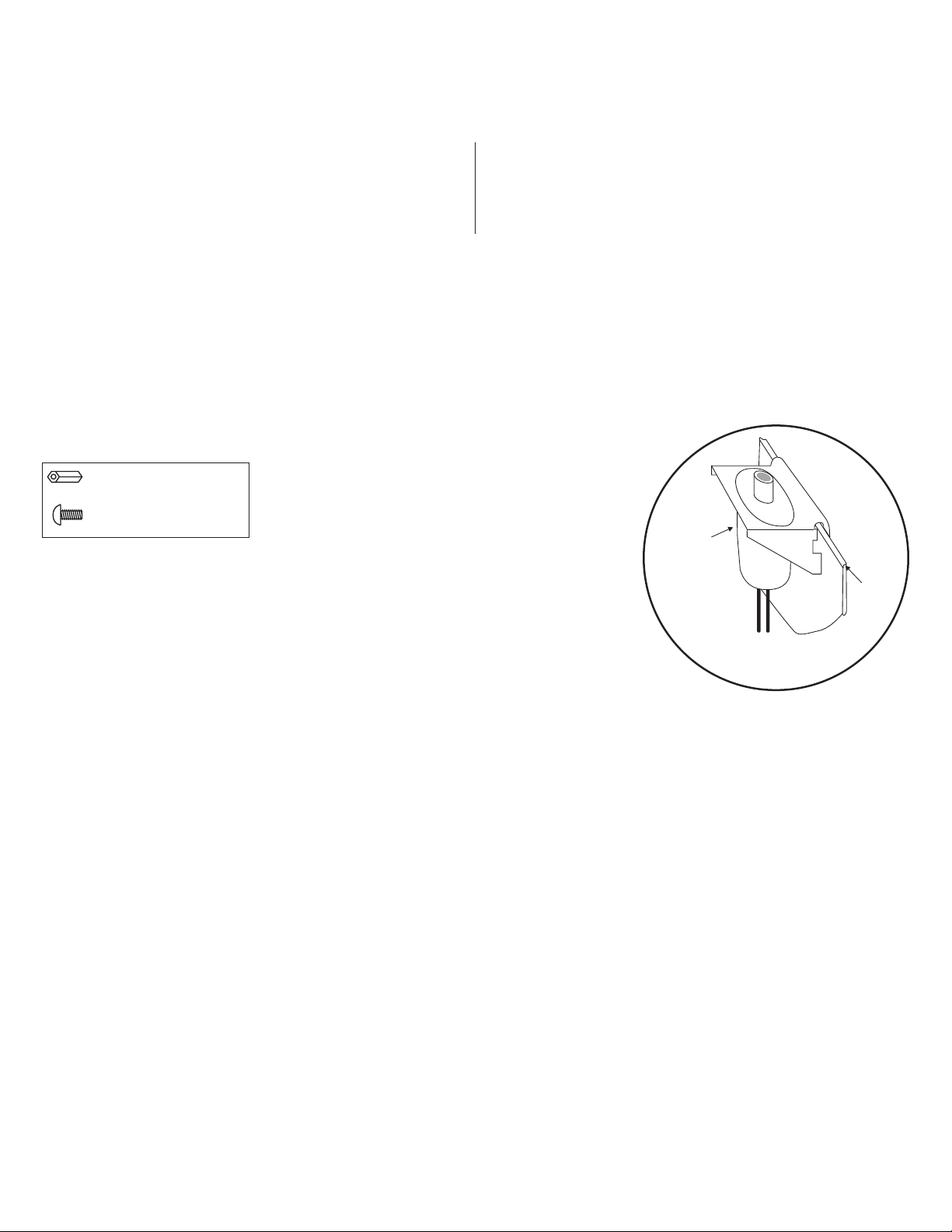
3. Mount UL Listed tamper switch (Honeywell Model 112 included or equivalent) in desired location, opposite hinge. Slide the tamper switch bracket
onto the edge of the enclosure approximately 2” from the right side (Fig. 1, pg. 2). Connect tamper switch wiring to the Access Control Panel
input or the appropriate UL Listed reporting device. To activate alarm signal open the door of the enclosure.
4. Mount Altronix/ZKTeco boards/modules to backplane, refer to pages 3-5.
Fig. 1
Hardware:
Nylon or Metal Standoff
5/16” Pan Head Screw
- 2 - Trove2Z2 / TZ2
Page 3
C
D
C
D
C D C D
C D C D
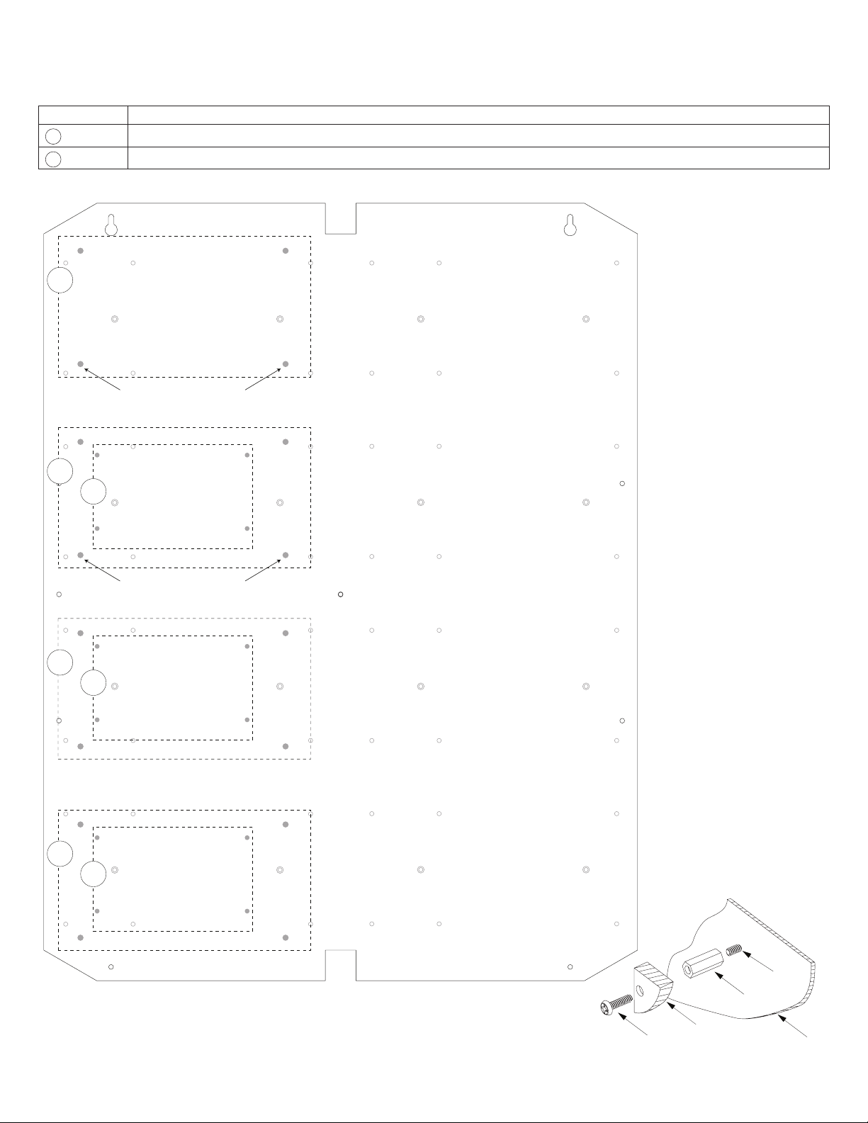
Installation Instructions for Altronix Power Supplies and/or Sub-Assemblies to TZ2:
1. Fasten standoffs (included) to pems that match the hole pattern for Altronix Power Supply/Chargers or Altronix Sub-Assembly boards
(Fig. 2, pg. 3). Fasten metal standoffs in the correct locations to provide proper grounding, see below (Fig. 2, pg. 3).
2. Mount boards to standoffs utilizing 5/16” pan head screws (included) (Fig. 2, 2a, pg. 3).
Pem Mounting Altronix Model
A AL400ULXB2, AL600ULXB, AL1012ULXB, AL1024ULXB2, eFlow4NB, eFLow6NB, eFlow102NB, eFlow104NB and ACM8(CB)
B ACM4(CB), PD4UL/PD4ULCB, PD8UL/PD8ULCB, MOM5, PDS8(CB) or VR6
Fig. 2 - Trove2Z2/TZ2 Configurations
A
Metal Standoff Placement
A
A
A
B
Metal Standoff Placement
B
B
Power Supply or
Pan Head
Screw
Trove2Z2 / TZ2 - 3 -
Sub-Assembly
Pem
Standoff
Fig. 2a
Backplane
Page 4
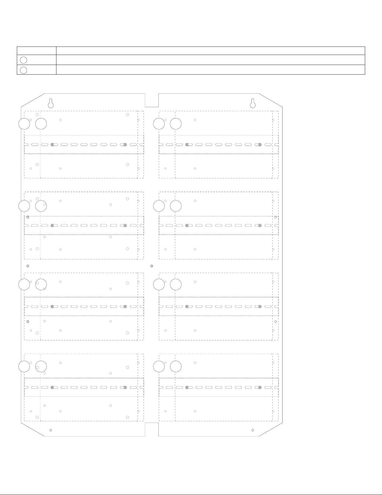
Installation Instructions for ZKTeco Modules to TZ2:
F
E
F
E
F
E
F
E
1. Fasten DIN Rail (provided by ZKTeco) to pem standoffs, utilizing 5/16” pan head screws (included) (Fig. 3, pg. 4).
2. Mount ZKTeco modules to DIN Rail (refer to below chart for model number, Fig. 3, pg. 4).
3. Fasten TZ2 backplane to Trove2 enclosure utilizing lock nuts (provided by Altronix).
Pem Mounting Altronix Model
C SMB/Pro Series inBio 460
D SMB/Pro Series inBio160/260
Fig. 3 - Trove2Z2/TZ2 Configurations
C
C
D
D
C
C
D
D
C D C D
C D C D
- 4 - Trove2Z2 / TZ2
Page 5
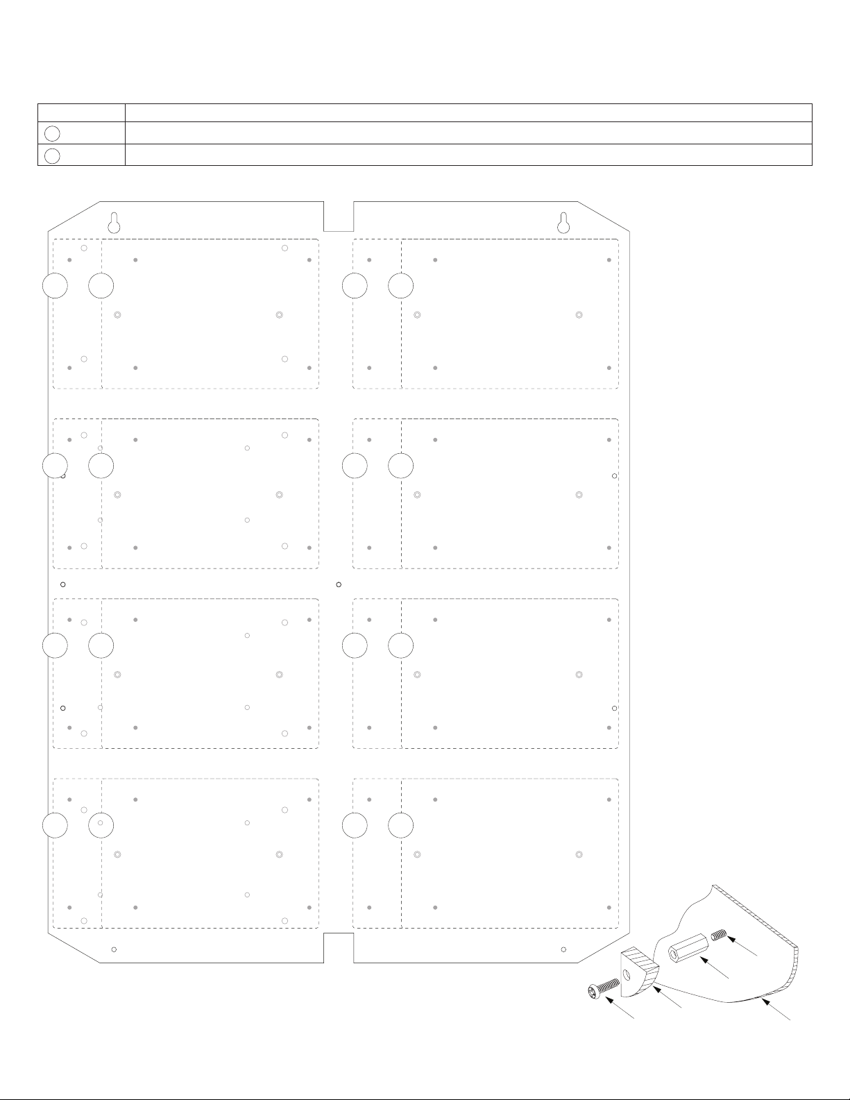
Installation Instructions for ZKTeco Boards to TZ2:
1. Fasten standoffs (provided) to pems that match the hole pattern for ZKTeco boards (refer to below chart for model number, Fig. 4, pg. 5).
2. Mount ZKTeco boards to standoffs utilizing 5/16” pan head screws (included) (refer to below chart for model number, Fig. 4, pg. 5).
3. Fasten TZ2 backplane to Trove2 enclosure utilizing lock nuts (included).
Pem Mounting Altronix Model
E SMB/Pro Series C3 400
F SMB/Pro Series C3 100/200
Fig. 4 - Trove2Z2/TZ2 Configurations
E
E
E
F
F
F
E
E
E
F
F
F
E
Trove2Z2 / TZ2 - 5 -
F
E
F
Pan Head
Screw
Pem
Standoff
ZKTeco
C3 100/200/400
Fig. 4a
Backplane
Page 6

eFlow Power Supply/Chargers can be Controlled and Monitored while
Reporting Power/Diagnostics from Anywhere over the Network...
LINQ2 - Network Communication Module
LINQ2 provides remote IP access to real-time data from eFlow power supply/chargers to help keep
systems up and running at optimal levels. It facilitates fast and easy installation and set-up, minimizes system downtime, and eliminates unnecessary service calls, which helps reduce Total Cost
of Ownership (TCO) - as well as creating a new source of Recurring Monthly Revenue (RMR).
LINQ2
Features:
- UL Listed in the U.S. and Canada.
- Local or remote control of up to (2) two Altronix eFlow power output(s) via LAN and/or WAN.
- Monitor real time diagnostics: DC output voltage, output current, AC & battery status/service, input trigger state change,
output state change and unit temperature.
- Access control and user managment: Restrict read/write, Restrict users to specific resources
- Two (2) integral network controlled Form “C” Relays.
- Three (3) programmable input triggers: Control relays and power supplies via external hardware sources.
- Email and Windows Dashboard notifications
- Event log tracks history.
- Secure Socket Layer (SSL).
- Programmable via USB or web browser - includes operating software and 6 ft. USB cable.
LINQ2 Mounts Inside any Trove Enclosure
LINQ2 Module
Network Connection:
Installation, Programming
and Monitoring
Altronix eFlow
Power Supply
- 6 - Trove2Z2 / TZ2
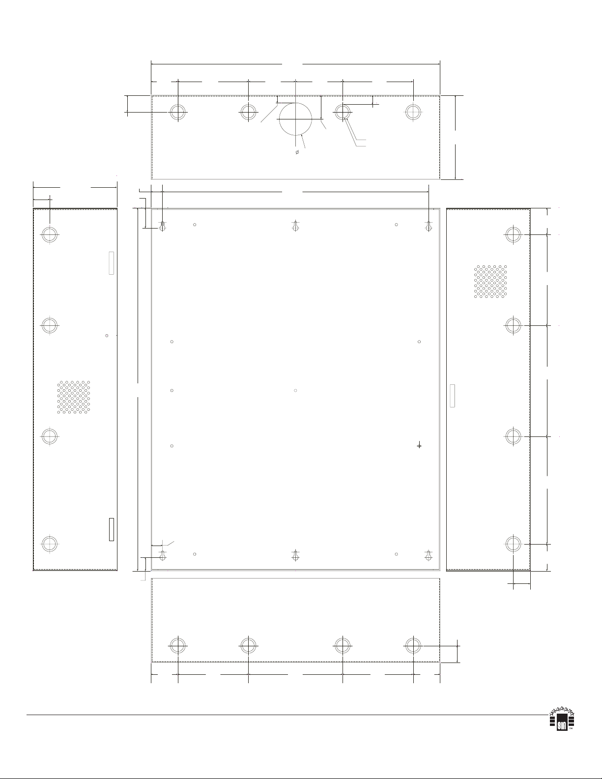
Page 7
24.95” (633.7mm)
TZ2 Dimensions (H x W x D):
25.375” x 19.375” x 0.325” (644.5mm x 482.6mm x 8.3mm)
19.375”
(482.6mm)
7.5”
(190.5mm)
7.5”
(190.5mm)
16.245” (412.6mm)
12.62” (320.6mm)
8.5” (215.8mm)
0.156”
( 3.96mm)
25.375”
(644.5mm)
12.62”
(320.6mm)
1.0”
(25.4mm)
0.45”
(11.4mm)
7.5”
(190.5mm)
1.0”
(25.4mm)
7.5”
(190.5mm)
9.2”
(233.7mm)
Trove2Z2 / TZ2 - 7 -
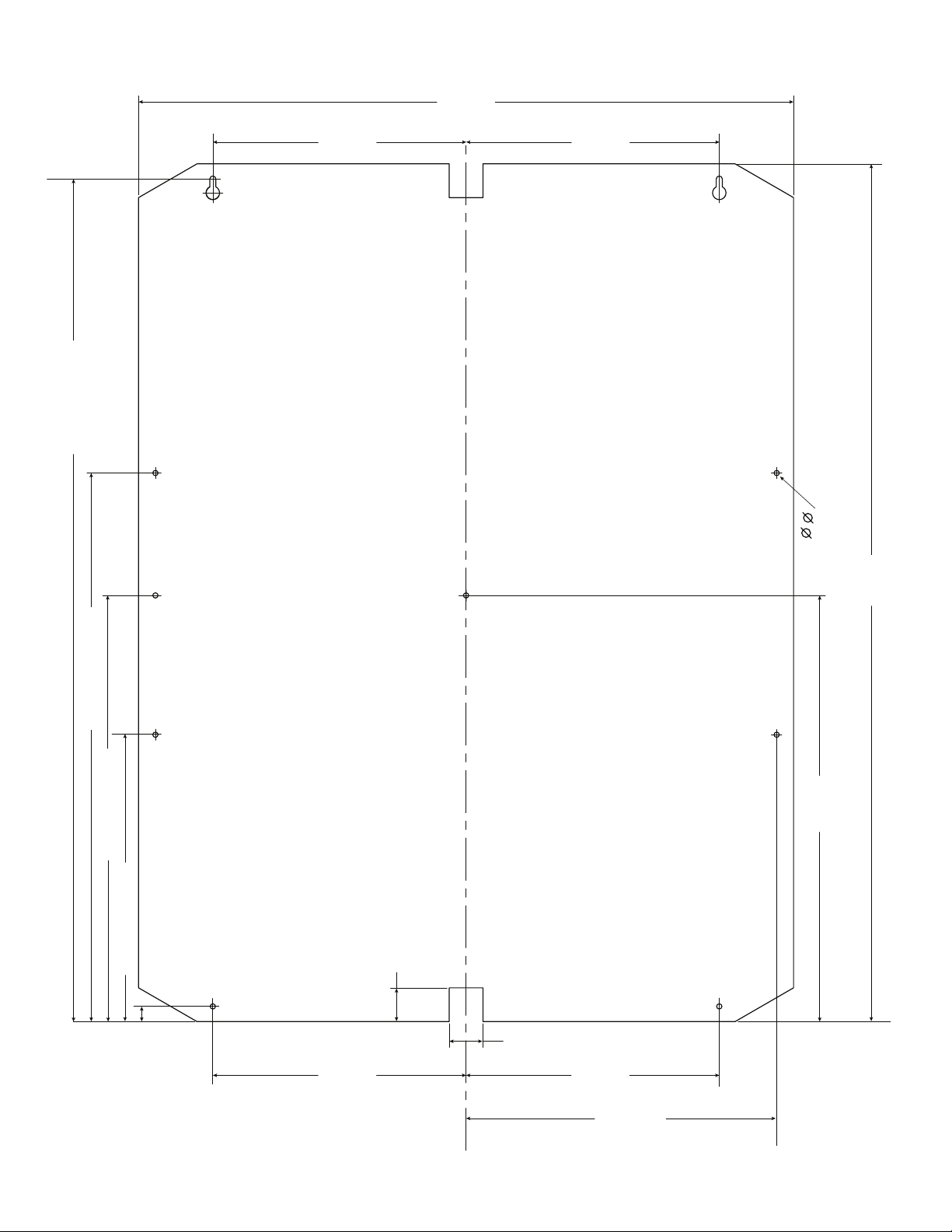
Page 8
1.25”
(
)
(
)
(
)
(
)
(
)
(31.75mm)
2.00”
(50.8mm)
Trove2Z2 Enclosure Dimensions (H x W x D):
27.25” x 21.75” x 6.5” (692.2mm x 552.5mm x 165.1mm)
21.50”
(546.1mm)
5.25”
(133.35mm)
3.50”
(88.9mm)
0.5625”
(14.29mm)
3.50”
(88.9mm)
(44.96mm)
2.415”
(61.34mm)
1.77”
5.25”
(133.35mm)
0.685”
(17.399mm)
Knockouts
1.125” (28.32mm)
0.885” (22.479mm)
6.25”
(158.75mm)
6.25”
(158.75mm)
1.25”
(31.75mm)
G
0.85”
(21.59mm)
1.5”
(38.1mm)
27.00”
(685.8mm)
19.80”
(502.92mm)
2.00”
(50.8mm)
6.75”
(171.45mm)
8.25”
(209.54mm)
8.00”
(203.2mm)
0.85”
(21.59mm)
2.00”
(50.8mm)
1.00”
(25.4mm)
1.25”
(31.75mm)
2.00”
50.8mm
Altronix is not responsible for any typographical errors.
140 58th Street, Brooklyn, New York 11220 USA | phone: 718-567-8181 | fax: 718-567-9056
web site: www.altronix.com | e-mail: info@altronix.com | Made in U.S.A.
IITrove2Z2 I10R
- 8 - Trove2Z2 / TZ2
5.25”
133.35mm
7.00”
177.79mm
5.25”
133.35mm
2.00”
50.8mm
1.25”
(31.75mm)
MEMBER
 Loading...