

Page 1

Edge of
Enclosure
to Access Control Panel
or U.L. Listed
Reporting Device
Enclosure
Honeywell
model # 112
Tamper Switch
or equivalent
(provided)
TKH2_Rev. 103017
Access & Power Integration
Trove2KH2 TKH2
- Trove2 enclosure with - Altronix/Kantech backplane only
Altronix/Kantech backplane (TKH2)
Installation Guide
Overview:
Trove2KH2 accommodates various combinations of Kantech boards with or without Altronix power supplies and accessories for access systems.
Specifications:
• 16 Gauge grey enclosure with ample knockouts for convenient access.
Enclosure Dimensions (H x W x D): 27.25” x 21.75” x 6.5” (692.2mm x 552.5mm x 165.1mm).
Trove2KH2
- Trove2 enclosure with TKH2 Altronix/Kantech backplane.
• Includes: tamper switch, cam lock, lock nuts and mounting hardware.
TKH2
- TKH2 Altronix/Kantech backplane.
• 16 Gauge backplane.
• Includes mounting hardware.
Dimensions (H x W x D): 25.375” x 19.375” x 0.5” (644.6mm x 492.1mm x 12.7mm).
Backplane accommodates a combination of the following:
• One (1) AL400ULXB2, AL600ULXB, AL1012ULXB, AL1024ULXB2, eFlow4NB, eFlow6NB, eFlow102NB, or eFlow104NB.
• One (1) T1618300.
• One (1) PDS8(CB), VR6, ACM8(CB), MOM5, PD4UL(CB), PD8UL(CB), or ACM4(CB).
• Four (4) KT-MOD-IN16 or KT-MOD-OUT16, or four (4) KT300, or three (3) KT400, or any combination of above.
Installation Instructions:
Wiring methods shall be in accordance with the National Electrical Code/NFPA 70/ANSI, and with all local codes and authorities having
jurisdiction. Product is intended for indoor use only.
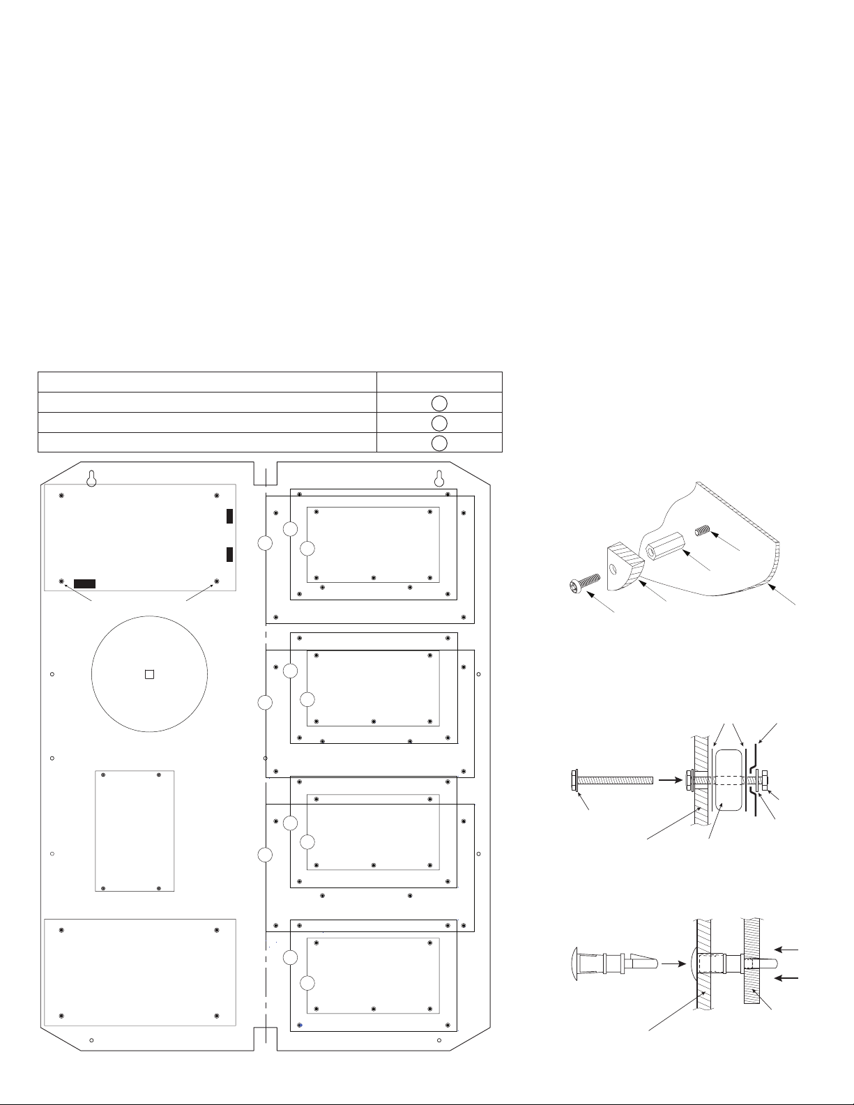
1. Remove backplane from enclosure. Do not discard hardware.
2. Mark and predrill holes on the wall to line up with the top three keyholes in the enclosure. Install three upper fasteners and screws in
the wall with the screw heads protruding. Place the enclosure’s upper keyholes over the three upper screws; level and secure.
Mark the position of the lower three holes. Remove the enclosure.
Drill the lower holes and install the three fasteners.
Place the enclosure’s upper keyholes over the three upper screws.
Install the three lower screws and make sure to tighten all screws.
3. Mount included UL Listed tamper switch (Honeywell Model 112 or equivalent) in
desired location, opposite hinge. Slide the tamper switch bracket onto the edge of the
enclosure approximately 2” from the right side (Fig. 1, pg. 1). Connect tamper switch
wiring to the Access Control Panel input or the appropriate UL Listed reporting device.
To activate alarm signal open the door of the enclosure.
4. Mount Altronix/Kantech boards to backplane, refer to page 2.
All registered trademarks are property of their respective owners.
Fig. 1
Page 2
TKH2: Configuration of Altronix Power Supply and/or Sub-Assembly Boards and Kantech Boards
1. Fasten standoffs (provided) to pems which match the hole pattern for Altronix Power Supply/Chargers or Altronix Sub-Assembly
boards (Fig. 2, pg. 2).
Note: Please fasten metal standoffs in the proper locations, see below (Fig. 2, pg. 2).
2. Mount boards to standoffs utilizing 3/8” pan head screws (provided) (Fig. 2a, pg. 2).
3. Mount Altronix T1618300 transformer to backplane and connect it as follows (Fig. 3, pg. 2):
a. Place one metal washer on the bolt, then push bolt through the square hole from the rear of backplane (Fig. 2b, pg. 2, Step 1).
b. Place first rubber washer on the bolt (Fig. 2b, pg. 2, Step 2).
c. Mount T1618300 on the bolt (Fig. 2b, pg. 2, Step 2).
d. Place second rubber washer on the bolt. Mount concave metal plate on top of the rubber washer as shown on Fig. 2b, pg. 2, Step 2.
e. Place second metal washer on the bolt. Tighten assembly with the nut (Fig. 2b, pg. 2, Step 2).
f. T1618300’s primary leads are black and white. Connect AC power 115VAC, 50/60Hz to them.
g. Measure output voltage across the secondary leads before connecting devices. This helps avoiding potential damage.
- Yellow and Brown for 16VAC (open circuit voltage @ 115VAC approx. 16.6VAC).
- Black and Brown for 18VAC (open circuit voltage @ 115VAC approx. 18.8VAC).
h. Connect 16VAC device(s) to Yellow and Brown leads or 18VAC device(s) to Black and Brown leads.
4. Mount appropriate Kantech boards into the correct positions (Fig. 2, pg. 2):
a. Position standoff over appropriate hole on the rear of backplane and depress it until it locks in place (Fig. 2c, pg. 2, Step 1).
b. Depress down on board to secure it to the standoff (Fig. 2c, pg. 2, Step 2).
5. Fasten backplane to Trove2 enclosure utilizing pan head screws (provided).
Kantech Access Controller Position Chart for the Following Models:
Kantech Board Pem Mounting
KT-400 Door Controller A
KT-300 Door Controller B
KT-MOD-IN16 or KT-MOD-OUT16 Expansion Modules C
Altronix
Power Supply
Metal Standoff Placement
Altronix
T1618300
Transformer
Altronix
Sub-
Assembly
Fig. 2
Fig. 2a
B
A
A
A
C
Altronix
Pan Head
Screw
B
C
Step 1
Bolt
B
C
Washer
TKH2
Power Supply or
Sub-Assembly
Step 2
T1618300
Standoff
Rubber
Washers
Pem
Backplane
Fig. 2b
Concave
Metal
Plate
Nut
Washer
Fig. 2c
Step 1
Altronix Sub-Assembly
- 2 - Trove2KH2/TKH2 - Altronix / Kantech
B
C
Kantech
Standoff
TKH2
Step 2
Kantech
Board
Page 3

(
)
(
)
0.45”
(11.4mm)
TKH2 Dimensions (H x W x D):
25.375” x 19.375” x 0.5” (644.6mm x 492.1mm x 12.7mm)
19.375”
(492.1mm)
7.5”
(190.5mm)
7.5”
(190.5mm)
0.156”
( 3.96mm)
25.375”
(644.6mm)
(11.4mm)
0.45”
9.2”
233.7mm
1.0” (25.4mm)
7.5”
(190.5mm)
16.25”
(412.8mm)
12.625”
(320.7mm)
8.5”
(215.9mm)
1.0” (25.4mm)
7.5”
(190.5mm)
9.2”
233.7mm
Trove2KH2/TKH2 - Altronix / Kantech - 3 -
Page 4
1.25”
(
)
(
)
(
)
(
)
(
)
(31.75mm)
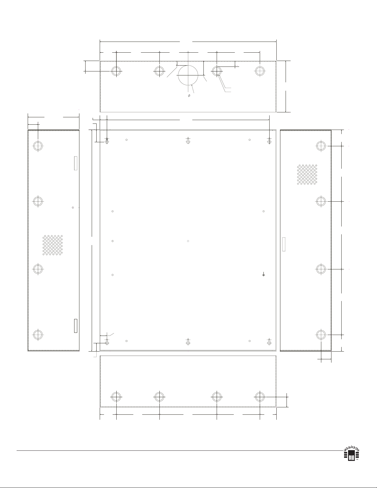
Enclosure Dimensions (H x W x D):
27.25” x 21.75” x 6.5” (692.2mm x 552.5mm x 165.1mm)
21.50”
(546.1mm)
2.00”
(50.8mm)
5.25”
(133.35mm)
3.50”
(88.9mm)
0.5625”
(14.29mm)
3.50”
(88.9mm)
(44.96mm)
2.415”
(61.34mm)
1.77”
5.25”
(133.35mm)
0.685”
(17.399mm)
Knockouts
1.125” (28.32mm)
0.885” (22.479mm)
6.25”
(158.75mm)
6.25”
(158.75mm)
1.25”
(31.75mm)
G
0.85”
(21.59mm)
1.5”
(38.1mm)
27.00”
(685.8mm)
19.80”
(502.92mm)
2.00”
(50.8mm)
6.75”
(171.45mm)
8.25”
(209.54mm)
8.00”
(203.2mm)
0.85”
(21.59mm)
2.00”
(50.8mm)
1.00”
(25.4mm)
2.00”
50.8mm
5.25”
133.35mm
7.00”
177.79mm
5.25”
133.35mm
2.00”
50.8mm
1.25”
(31.75mm)
1.25”
(31.75mm)
Altronix is not responsible for any typographical errors.
140 58th Street, Brooklyn, New York 11220 USA | phone: 718-567-8181 | fax: 718-567-9056
web site: www.altronix.com | e-mail: info@altronix.com | Made in U.S.A.
IITrove2KH2 I10R
- 4 - Trove2KH2/TKH2 - Altronix / Kantech
MEMBER
 Loading...