

Page 1

Access & Power Integration
Trove2HN2
- Trove2 enclosure with Altronix/Honeywell NetAXS backplane (THN2)
THN2
- Altronix/Honeywell NetAXS backplane only
Installation Guide
All registered trademarks are property of their respective owners. More than just power.™
Rev. THN052518
Installing Company: _____________________ Service Rep. Name: __________________________________________
Address: ________________________________________________________ Phone #: _________________________
Page 2

Overview:
Edge of
Enclosure
to Access Control Panel
or U.L. Listed
Reporting Device
Enclosure
Honeywell
model # 112
Tamper Switch
or equivalent
(provided)
Trove2HN2 accommodates various combinations of Honeywell NetAXS boards with or without Altronix power supplies and accessories
for access systems.
Specifications:
Trove2HN2
- Trove2 enclosure with THN2 Altronix/Honeywell backplane.
• Includes: tamper switch, cam lock, mounting hardware.
• 16 Gauge grey enclosure with ample knockouts for convenient access.
Enclosure Dimensions (H x W x D): 27.25” x 21.75” x 6.5” (692.2mm x 552.5mm x 165.1mm).
Accommodates up to four (4) 12VDC/7AH batteries.
THN2
- THN2 Altronix/Honeywell backplane.
• 16 Gauge backplane.
• Includes mounting hardware.
Dimensions (H x W x D): 25.375” x 19.375” x 0.3125” (644.6mm x 492.1mm x 7.9mm).
THN2 accommodates a combination of the following:
Altronix:
• Up to four (4) AL400ULXB2, AL600ULXB, AL1012ULXB, AL1024ULXB2, eFlow4NB, eFlow6NB, eFlow102NB, or eFlow104NB.
• Up to four (4) ACM8(CB) or ACM8S(CB).
• Up to three (2) ACM4(CB), MOM5, PD4UL(CB), PD8UL(CB), PDS8(CB), or VR6.
Honeywell:
• Up to four (4) NX4PCB access control panels.
• Up to eight (8) NetAXS-123 access control panels.
• Up to eight (8) NXD1 or NXD2 add-on boards.
• Up to four (4) NX4IN or NX4OUT boards.
Installation Instructions:
Wiring methods shall be in accordance with the National Electrical Code/NFPA 70/ANSI, and with all local codes and authorities having
jurisdiction. Product is intended for indoor use only.
1. Remove backplane from enclosure. Do not discard hardware.
2. Mark and predrill holes in the wall to line up with the top three keyholes in the enclosure. Install three upper fasteners and screws
in the wall with the screw heads protruding. Place the enclosure’s upper keyholes over the three upper screws; level and secure.
Mark the position of the lower three holes. Remove the enclosure. Drill the lower holes and install
the three fasteners. Place the enclosure’s upper keyholes over the three upper screws.
Install the three lower screws and make sure to tighten all screws.
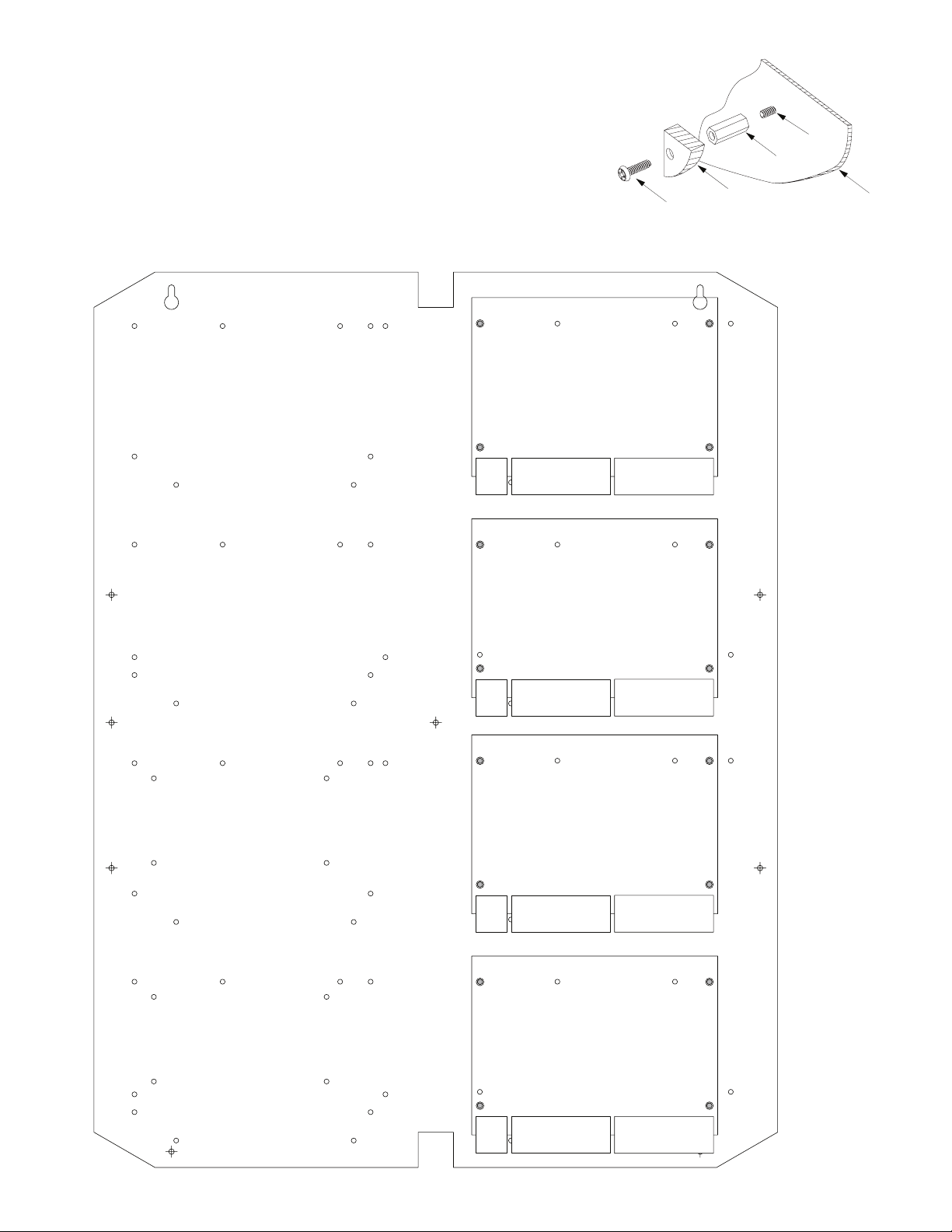
3. Mount included UL Listed tamper switch (Honeywell Model 112 or equivalent)
in desired location, opposite hinge. Slide the tamper switch bracket onto the edge of the
enclosure approximately 2” from the right side (Fig. 1, pg. 2). Connect tamper switch
wiring to the Access Control Panel input or the appropriate UL Listed reporting device.
To activate alarm signal open the door of the enclosure.
4. Mount Altronix/Honeywell boards to backplane, refer to pages 3-6.
Fig. 1
- 2 - TroveHN
Page 3
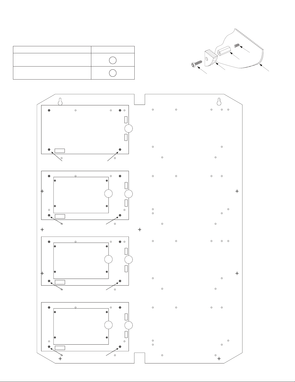
Installation Instructions for Altronix Power Supplies and Sub-Assemblies to THN2:
1. Fasten standoffs (provided) into pem configuration (A) or (B) of backplane (Fig. 2, pg. 3).
2. Mount boards to standoffs utilizing 5/16” pan head screws (provided) (Fig. 2a, pg. 3).
3. Mount backplane to enclosure with hardware.
Access Controller Position Chart for the Following Models:
Altronix Board Pem Mounting
Altronix Power Supply/Charger or
Sub-Assembly
A
Fig. 2a
Pem
Standoff
Altronix Sub-Assembly B
Fig. 2
Metal Standoff Placement
B
A
A
Pan Head
Screw
Altronix
Power Supply or
Sub-Assembly
Backplane
Metal Standoff Placement
Metal Standoff Placement
Metal Standoff Placement
B
B
A
A
TroveHN - 3 -
Page 4

Installation Instructions for Honeywell NX4PCB to THN2:
1. Fasten standoffs (provided) to appropriate pems on backplane (Fig. 3, pg. 4).
2. Mount boards to standoffs utilizing 5/16” pan head screws (provided) (Fig. 3a, pg. 4).
Note: Honeywell NX4PCB modules have one (1) RJ45 jack each.
Please make sure that they are mounted correctly, as shown in Fig. 3 below.
3. Mount backplane to enclosure with hardware.
Fig. 3a
Pem
Standoff
Fig. 3
RJ45 Jack
NX4PCB
RJ45 Jack
NX4PCB
Pan Head
Screw
Honeywell
Access Controller
Backplane
RJ45 Jack
NX4PCB
- 4 - TroveHN
RJ45 Jack
NX4PCB
Page 5

Installation Instructions for Honeywell NetAXS-123 with/without NXD1/NXD2 to THN2:
Bottom of
N
1. Fasten standoffs (provided) to appropriate pems on backplane (Fig. 4, pg. 5).
2. Mount boards to standoffs utilizing 5/16” pan head screws (provided) (Fig. 4a, pg. 5).
Note: Honeywell NetAXS-123 modules have one (1) RJ45 jack each.
Please make sure that they are mounted correctly, as shown in Fig. 4 below.
In order to properly mount and connect NXD1/NXD2 do the following:
- prior to mounting on backplane, attach NXD1/NXD2 to the NetAXS-123
by connecting the multi-pin connector on the bottom of NXD1/NXD2 to the
multi-pin jack on NetAXS-123. Make sure that pre-installed bump screws on
NXD1/NXD2 go through the corresponding holes in NetAXS-123.
- secure NXD1/NXD2 to NetAXS-123 using pre-installed bump screws
and included standoffs (Fig. 4b, pg. 5).
- after NXD1/NXD2 is firmly attached and connected to NetAXS-123,
follow steps 1 and 2 above to mount them onto THN2.
3. Mount backplane to enclosure with hardware.
Pan Head
Screw
XD1/NXD2
Honeywell
Access Controller
Standoff
Fig. 4a
Pem
Backplane
Fig. 4b
Fig. 4
RJ45 Jack
NXD1 or NXD2
NetAXS-123
RJ45 Jack
NXD1 or NXD2
NetAXS-123
RJ45 Jack
NXD1 or NXD2
NetAXS-123
RJ45 Jack
NXD1 or NXD2
NetAXS-123
Mounting
Hole
Pre-installed
Bump Screw
Standoff
Bottom of NetAXS-123
RJ45 Jack
NXD1 or NXD2
NetAXS-123
RJ45 Jack
RJ45 Jack
NXD1 or NXD2
NetAXS-123
RJ45 Jack
TroveHN - 5 -
NXD1 or NXD2
NetAXS-123
NXD1 or NXD2
NetAXS-123
Page 6
Installation Instructions for Honeywell NX4IN or NX4OUT to THN2:
1. Fasten standoffs (provided) to appropriate pems on backplane (Fig. 5, pg. 6).
2. Mount boards to standoffs utilizing 5/16” pan head screws (provided) (Fig. 5a, pg. 6).
3. Mount backplane to enclosure with hardware.
Fig. 5a
Pem
Standoff
Fig. 5
Pan Head
Screw
NX4IN or NX4OUT
NX4IN or NX4OUT
Honeywell
Access Controller
Backplane
NX4IN or NX4OUT
NX4IN or NX4OUT
- 6 - TroveHN
Page 7

(
)
(
)
0.45”
(11.4mm)
THN2 Dimensions (H x W x D):
25.375” x 19.375” x 0.3125” (644.6mm x 492.1mm x 7.9mm)
19.375”
(492.1mm)
2.2”
(55.9mm)
2.2”
(55.9mm)
0.156”
( 3.96mm)
25.375”
(644.6mm)
(11.4mm)
0.45”
9.2”
233.7mm
1.0” (25.4mm)
7.5”
(190.5mm)
16.25”
(412.8mm)
12.625”
(320.7mm)
8.5”
(215.9mm)
1.0” (25.4mm)
7.5”
(190.5mm)
9.2”
233.7mm
TroveHN - 7 -
Page 8

1.25”
(
)
(
)
(
)
(
)
(
)
(31.75mm)
Trove2HN2 Enclosure Dimensions (H x W x D approximate):
27.25” x 21.75” x 6.5” (692.2mm x 552.5mm x 165.1mm)
21.50”
(546.1mm)
2.00”
(50.8mm)
5.25”
(133.35mm)
3.50”
(88.9mm)
0.5625”
(14.29mm)
3.50”
(88.9mm)
(44.96mm)
2.415”
(61.34mm)
1.77”
5.25”
(133.35mm)
0.685”
(17.399mm)
Knockouts
1.125” (28.32mm)
0.885” (22.479mm)
6.25”
(158.75mm)
6.25”
(158.75mm)
1.25”
(31.75mm)
G
0.85”
(21.59mm)
1.5”
(38.1mm)
27.00”
(685.8mm)
19.80”
(502.92mm)
2.00”
(50.8mm)
6.75”
(171.45mm)
8.25”
(209.54mm)
(203.2mm)
0.85”
(21.59mm)
(50.8mm)
1.00”
(25.4mm)
1.25”
(31.75mm)
2.00”
50.8mm
Altronix is not responsible for any typographical errors.
140 58th Street, Brooklyn, New York 11220 USA | phone: 718-567-8181 | fax: 718-567-9056
web site: www.altronix.com | e-mail: info@altronix.com | Made in U.S.A.
IITroveHN I10R
- 8 - TroveHN
5.25”
133.35mm
7.00”
177.79mm
5.25”
133.35mm
2.00”
50.8mm
1.25”
(31.75mm)
8.00”
2.00”
MEMBER
 Loading...