

Page 1
Access & Power Integration
Edge of
Enclosure
to Access Control Panel
or U.L. Listed
Reporting Device
Enclosure
Honeywell
model # 112
Tamper Switch
or equivalent
(provided)
Trove2BH2 TBH2
- Trove2 enclosure with - Altronix/Bosch backplane only
Altronix/Bosch backplane (TBH2)
Installation Guide
TBH2_Rev. 103017
Overview:
Trove2BH2 accommodates various combinations of Bosch boards with or without Altronix accessories for access control systems.
Installation Instructions for Trove2:
1. Remove backplane from enclosure prior to mounting (do not discard hardware).
2. Mark and predrill holes in the wall to line up with the top keyholes in the enclosure. Install the upper fasteners and screws in the wall
with the screw heads protruding. Place the enclosure’s upper keyholes over the screws; level and secure. Mark the position of the
lower holes. Remove the enclosure. Drill the lower holes and install the fasteners.
Place the enclosure’s upper keyholes over the upper screws. Install the lower screws and make sure to tighten all screws
(Enclosure Dimensions, pg. 4).
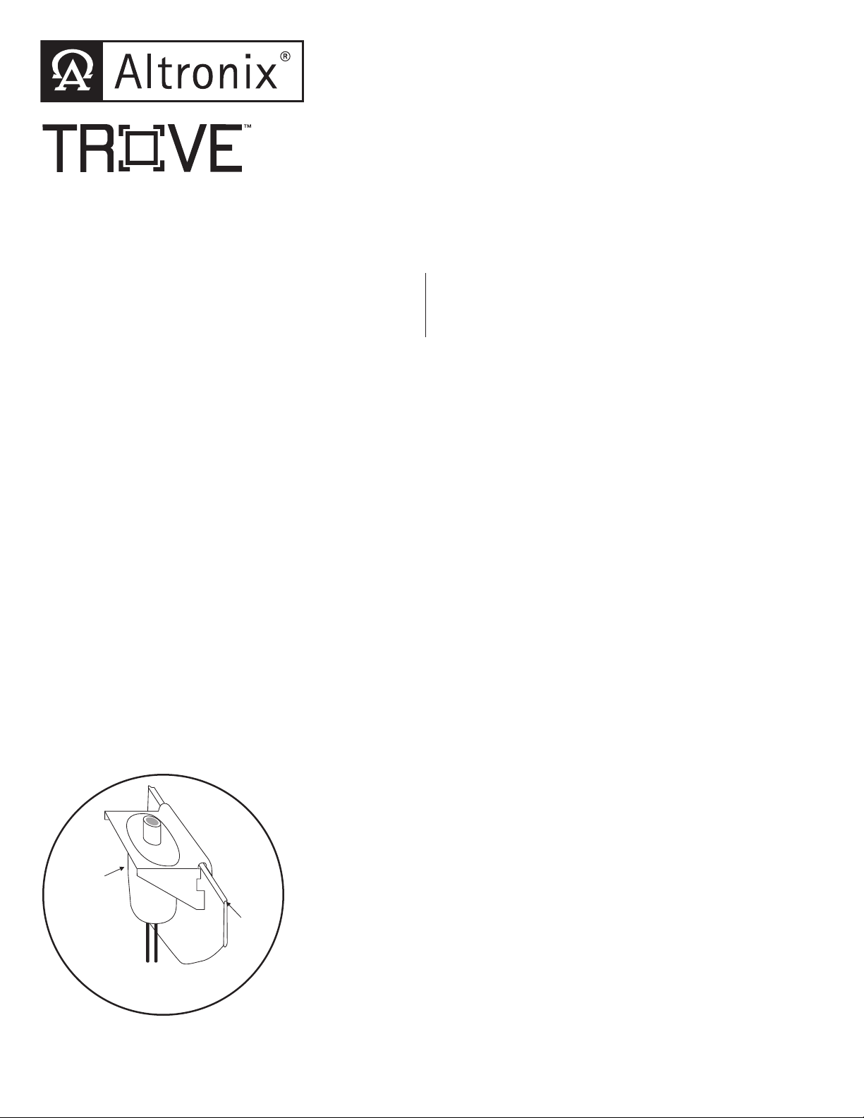
3. Mount included UL Listed tamper switch (Honeywell Model 112 or equivalent) in desired location, opposite hinge. Slide the tamper
switch bracket onto the edge of the enclosure approximately 2” from the right side (Fig. 1, pg. 1).
Connect tamper switch wiring to the Access Control Panel input or the appropriate UL Listed reporting device.
To activate alarm signal open the door of the enclosure.
4. Mount Altronix/Bosch boards to backplane, refer to pages 2-3.
Fig. 1
All registered trademarks are property of their respective owners.
Page 2
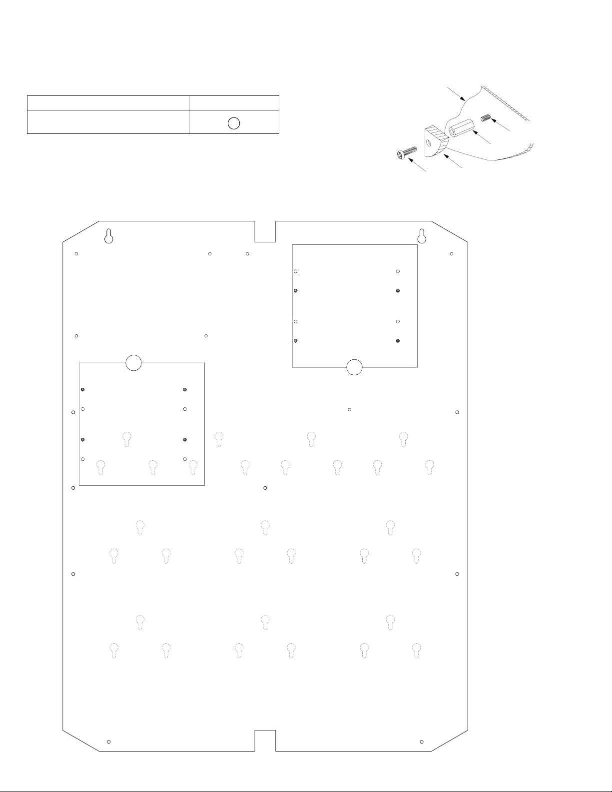
Installation Instructions for Altronix Sub-Assemblies to TBH2:
1. Insert screw (provided) into hole configuration (A) from the backside of backplane (Fig. 2a, pg. 2).
Screw standoff onto screws, repeat for additional three (3) board mounting holes.
2. Mount boards to standoffs utilizing 5/16” pan head screws (provided) (Fig. 2a, pg. 2).
Altronix Sub-Assemblies Position Chart:
Altronix Board Pem Mounting
Backplane
Fig. 2a
Altronix PD16W(CB) Sub-Assembly A
Fig. 2
A
A
Pan Head
Screw
Pan Head Screw
(through backplane)
Standoff
Altronix
Sub-Assembly
- 2 - Trove2BH2
Page 3

Installation Instructions for Bosch Boards to TBH2:
Mounting Bosch B520 Power Supply:
1. Fasten standoffs (provided) into hole configuration (A) of backplane (Fig. 3, pg. 3).
2. Mount boards to standoffs utilizing 5/16” pan head screws (provided) (Fig. 3a, pg. 3).
Mounting Bosch B8512G/B9512G IP Control Panels:
1. Fasten lock nuts onto top two (2) pems, leaving enough space to accommodate B8512G/B9512G.
2. Slide top mounting holes of B8512G/B9512G over pems of backplane configuration (B) (Fig. 3, pg. 3).
3. Fasten 5/16” pan head screw (provided) through mounting hole of B8512G/B9512G (Fig. 3a, pg. 3).
Mounting Bosch Modules:
1. Utilize mounting bracket to mount Bosch modules to the backplane configurations (C)
(Fig. 3, pg. 3).
Bosch Board Position Chart:
Bosch Board(s) Mounting
Power Supply
Controllers
Access Control*
Expansion Modules*
Interface Cards*
SDI/2 Devices*
B520 A
D7412GV4, D9412GV4, B8512G, B9512G B
B901
B299, B600, D8128D, D8125/MUX, D8129
D125B, D129, D132A, D185, D192G, D8130
B208, B308, B426, B450, ICP-SDI-9114
C
Fig. 3
A
Backplane
Pan Head
Screw
Fig. 3a
Pem
Standoff
Bosch
Sub-Assembly
B
C
C
C
C C C
C
C C C
* These boards have the same keyhole
mounting bracket (Fig. 3, pg. 3). Position
them according to your specific design.
Trove2BH2 - 3 -
Page 4

1.25”
(
)
(
)
(
)
(
)
(
)
(31.75mm)
Trove2 Enclosure Dimensions (H x W x D approximate):
27.25” x 21.75” x 6.5” (692.15mm x 552.5mm x 165.1mm)
21.50”
(546.1mm)
2.00”
(50.8mm)
5.25”
(133.35mm)
3.50”
(88.9mm)
0.5625”
(14.29mm)
3.50”
(88.9mm)
(44.96mm)
2.415”
(61.34mm)
1.77”
5.25”
(133.35mm)
0.685”
(17.399mm)
Knockouts
1.125” (28.32mm)
0.885” (22.479mm)
6.25”
(158.75mm)
6.25”
(158.75mm)
1.25”
(31.75mm)
G
0.85”
(21.59mm)
1.5”
(38.1mm)
27.00”
(685.8mm)
19.80”
(502.92mm)
2.00”
(50.8mm)
6.75”
(171.45mm)
8.25”
(209.54mm)
(203.2mm)
0.85”
(21.59mm)
(50.8mm)
1.00”
(25.4mm)
1.25”
(31.75mm)
2.00”
50.8mm
Altronix is not responsible for any typographical errors.
140 58th Street, Brooklyn, New York 11220 USA | phone: 718-567-8181 | fax: 718-567-9056
web site: www.altronix.com | e-mail: info@altronix.com | Made in U.S.A.
IITrove2BH2 I10R
- 4 - Trove2BH2
5.25”
133.35mm
7.00”
177.79mm
5.25”
133.35mm
2.00”
50.8mm
1.25”
(31.75mm)
8.00”
2.00”
MEMBER
 Loading...