

Page 1

Versatile Access Power
and Integration Enclosures
Installation Guide
Includes Models:
Trove1
Trove2
Rev.062016 More than just power.™
Page 2
Trove accommodates various combinations of access controllers and accessories from the industry’s
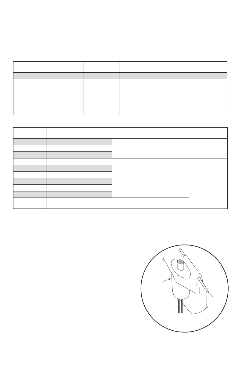
Edge of
Enclosure
to Access Control Panel
or U.L. Listed
Reporting Device
Enclosure
Honeywell
model # 112
Tamper Switch
or equivalent
(provided)
Overview:
leading manufacturers with or without Altronix power supplies and accessories for access systems.
• 19 Gauge grey enclosure with ample knockouts for convenient access.
Trove Model Identification:
Specifications:
Series
Trove 2 M 1 3 F
Enclosure Size
(H” x W” x D”)
1 = 18” x 14.5” x 4.625”
2 = 27.25” x 21.75” x 6.5”
Backplane
Model
AM = AMAG
C / CV = CDVI
KA = Keyscan
M = Mercury
SH = Software
House
V = HID/Vertx
Power Supply 1 Power Supply 2
1 = 4A
3 = 6A
5 = 10A/12VDC
7 = 10A/24VDC
1 = 4A
3 = 6A
5 = 10A/12VDC
7 = 10A/24VDC
Blank = Not installed
Power Supply
Feature Set
Blank = ULXB
F = eFlow
Backplane Model Identification:
Backplane
Model
TC1 CDVI
TV1 HID/Vertx
TAM2 AMAG
TCV2 CDVI
TKA2 Keyscan
TM2 Mercury
TSH2 Software House
TV2 HID/Vertx
TMV2 Mercury/Vertx door backplane
Manufacturer Dimensions (H x W x D)
16.65” x 12.5” x 0.3125”
(422.9mm x 321.3mm x 7.9mm)
25.4” x 19.4” x 0.3125”
(645.16mm x 492.76mm x 7.9mm)
23.75” x 18.125” x 0.3125”
(603.25mm x 460.4mm x 7.9mm)
Trove
Enclosure
Trove1TM1 Mercury
Trove2
1. Remove backplane from enclosure. Do not discard hardware.
Installation Instructions:
2. Mark and predrill holes in the wall to line up with the top two/three keyholes in the enclosure.
Install three upper fasteners and screws in the wall with the screw heads protruding.
Place the enclosure’s upper keyholes over the two/three upper screws; level and secure.
Mark the position of the lower three holes. Remove the enclosure.
Drill the lower holes and install the two/three fasteners. Place the
enclosure’s upper keyholes over the two/three upper screws.
Install the two/three lower screws and make sure to
tighten all screws.
3. Mount included UL Listed tamper switch
(Ademco model 112 or equivalent) in desired location,
opposite from hinge. Slide the tamper switch bracket onto
the edge of the enclosure approximately 2” from the
right side (Fig. 1, pg. 2). Connect tamper switch
wiring to the Access Control Panel input or the
appropriate UL Listed reporting device.
To activate alarm signal open the door of the enclosure.
4. Mount boards to backplane, refer to individual
backplane installation instructions.
- 2 - Trove
Fig. 1
Page 3

Power Supply Specifications:
Power Supply
Model #
AL400ULXB2 1 115VAC, 60Hz, 3.5A 4A 3A 4AH
AL600ULXB 3 115VAC, 60Hz, 3.5A 6A 7AH
AL1012ULXB 5 115VAC, 60Hz, 2.6A 10A ---- 12AH
AL1024ULXB2 7 115VAC, 60Hz, 4.2A ---- 10A 12AH
eFlow4NB 1F 115VAC, 60Hz, 3.5A 4A 3A 4AH
eFlow6NB 3F 115VAC, 60Hz, 3.5A 6A 7AH
eFlow102NB 5F 115VAC, 60Hz, 3.5A 10A ---- 12AH
eFlow104NB 7F 115VAC, 60Hz, 4.5A ---- 10A 12AH
Identification
Code
Input
Output
12VDC 24VDC
Battery Size for
30 min. Backup
Wiring methods shall be in accordance with the National Electrical Code/NFPA 70/ANSI, and with all
Installation Instructions:
local codes and authorities having jurisdiction. Product is intended for indoor use only.
1. The power supply is pre-wired to the ground (chassis). Connect main incoming ground to the
provided green grounding conductor lead. Connect unswitched AC power (115VAC 60Hz) to the
terminals marked [L, N] on a single or both power supply boards. Use 14 AWG or larger for all
power connections.
Keep power-limited wiring separate from non power-limited wiring.
Minimum 0.25” spacing must be provided.
CAUTION: Do not touch exposed metal parts. Shut branch circuit power before installing
or servicing equipment. There are no user serviceable parts inside. Refer installation
and servicing to qualified service personnel.
2. Select desired DC output voltage by setting SW1 to the appropriate position on the
AL400ULXB2, AL600ULXB, eFlow4NB and eFlow6NB power supply (Figs. 2 and 2a, pg. 4).
AL1012ULXB and eFlow102NB power supplies are factory set at 12VDC.
AL1024ULXB2 and eFlow104NB power supplies are factory set at 24VDC.
3. Measure the output voltage of the unit before connecting any devices to ensure proper operation.
Improper or high voltage will damage these devices.
4. Connect devices or Altronix sub-assembly modules to be powered to the terminals marked
[-- DC +].
eFlow Power Supply: For auxiliary device connection, this output will not be affected by
Low Power Disconnect or Fire Alarm Interface. Connect device to the terminals
marked [+ AUX -- ].
5. For Access Control applications batteries are optional. When batteries are not used, a loss of AC
will result in the loss of output voltage. When the use of stand-by batteries is desired, they must
be lead acid or gel type. Connect battery to the terminals marked [-- BAT + ]. Use two (2)
12VDC batteries connected in series for 24VDC operation (battery leads included). Use batteries
Casil CL1270 (12V/7AH), CL12120 (12V/12AH), CL12400 (12V/40AH), CL12650 (12V/65AH)
batteries or UL recognized BAZR2 batteries of an appropriate rating.
6. Connect appropriate signaling notification devices to AC FAIL & BAT FAIL supervisory
relay outputs.
7. eFlow Power Supply:
To delay AC reporting for 2 hrs., set dip switch [AC Delay] to OFF position.
To delay AC reporting for 1 min., set dip switch [AC Delay] to ON position.
Note: Must be set to ON position for Burglar Alarm Applications.
8. eFlow Power Supply:
To enable Fire Alarm Disconnect set dip switch [Shutdown] to ON position.
To disable Fire Alarm Disconnect set dip switch [Shutdown] to OFF position.
9. eFlow Power Supply:
Trigger terminals are end of a line resistor supervised (10k Ohms). Opening or shorting trigger
terminals will cause [DC] output to shutdown.
10. eFlow Power Supply:
Place a jumper for non-latching FACP. A momentary short on these terminals resets FACP
latching [Trigger EOL Shutdown].
11. Please ensure that the cover is secured with the provided key lock.
Trove - 3 -
Page 4

Fig. 2
OFF - 24V
ON - 12V
Power Supply Board Output Voltage Settings:
OFF - 24V
ON - 12V
ON
SW1
ON
ON
+ DC ---
OFF - 24V
ON - 12V
--- DC +
AL400ULXB2/AL600ULXB
Power Supply Board
eFlow4NB/eFlow6NB
Power Supply Board
- 4 - Trove
Page 5

Trove - 5 -
Page 6

- 6 - Trove
Page 7

1.25”
(31.75mm)
1.5”
(38.09mm)
0.569”
(14.52mm)
Trove1 Enclosure Dimensions (H x W x D):
18” x 14.5” x 4.6255” (457mm x 368mm x 118mm)
14.5”
4.5”
(114.3mm)
0.5897”
(14.98mm)
7.25”
(184.15mm)
1.45”
(36.83mm)
13.0”
(330.2mm)
(321.31mm)
1.948”
(49.483mm)
1.25”
(31.75mm)
1.5”
(38.09mm)
8.5”
(215.9mm)
6.5”
(165.1mm)
18.0”
(457.2mm)
0.6012”
(15.27mm)
(27.83mm)
1.0958”
4.5”
(114.3mm)
(114.3mm)
1.115”
(28.32mm)
1.362”
(34.59mm)
8.5”
(215.9mm)
6.5”
(165.1mm)
4.5”
2.75”
(69.85mm)
1.25”
(31.75mm)
Trove - 7 -
Page 8

6.25”
(
)
(
)
(
)
(
)
(
)
(158.75mm)
1.25”
(31.75mm)
Trove2 Enclosure Dimensions (H x W x D):
27.25” x 21.75” x 6.5” (692.15mm x 552.45mm x 165.1mm)
21.50”
(546.1mm)
2.415”
(61.34mm)
19.80”
(502.92mm)
3.50”
(88.9mm)
1.77”
(44.96mm)
5.25”
(133.35mm)
0.685”
(17.399mm)
Knockouts
1.125” (28.32mm)
0.885” (22.479mm)
(31.75mm)
G
1.25”
0.85”
(21.59mm)
1.5”
(38.1mm)
27.00”
(685.8mm)
2.00”
(50.8mm)
5.25”
(133.35mm)
(88.9mm)
0.5625”
(14.29mm)
3.50”
6.25”
(158.75mm)
2.00”
(50.8mm)
6.75”
(171.45mm)
8.25”
(209.54mm)
8.00”
(203.2mm)
0.85”
(21.59mm)
2.00”
(50.8mm)
1.00”
(25.4mm)
2.00”
50.8mm
5.25”
133.35mm
7.00”
177.79mm
5.25”
133.35mm
2.00”
50.8mm
1.25”
(31.75mm)
1.25”
(31.75mm)
Altronix is not responsible for any typographical errors. Product specifications are subject to change without notice.
140 58th Street, Brooklyn New York 11220 USA, 718-567-8181, fax: 718-567-9056
website: www.altronix.com, e-mail: info@altronix.com. Made in USA.
IITrove - Rev. 06202016 G26P
- 8 - Trove
MEMBER
 Loading...