

Page 1

TM1
SIGNALING
Trove1M1
TM2
Trove2M2
Installation Instructions
Rev. TMERC011117
More than just power.™
All registered trademarks are property of their respective owners.
Page 2
Installation Instructions for Trove1 and Trove2:
Access Controller
1. Remove back plane from enclosure prior to mounting (do not discard hardware).
2. Mark and predrill holes in the wall to line up with the top keyholes in the enclosure. Install the upper fasteners and screws in the wall
with the screw heads protruding. Place the enclosure’s upper keyholes over the screws, level and secure. Mark the position of the
lower holes. Remove the enclosure. Drill the lower holes and install the fasteners. Place the enclosure’s upper keyholes
over the upper screws. Install the lower screws and make sure to tighten all screws (Enclosure Dimensions, pgs. 6-7).
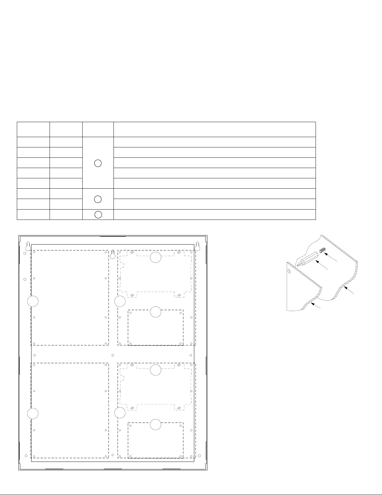
Installation Instructions for Mercury Access Controllers to TM1:
1. Fasten female/male standoffs onto metal pems configuration (A) (B) (C) of back plane depending on
the access controller (Fig. 1, pg. 2).
2. Position access controller module over corresponding standoffs and depress onto female/male standoffs (Fig. 1a, pg. 2).
3. Mount back plane to enclosure with hardware.
Access Controller Position Chart for the Following Models:
Mercury Lenel
EP1502 LNL-2220
EP4502 LNL-4420 12-24VDC 500mA max.
MR16IN LNL-1100 12-24VDC 350mA max. (12VDC @ 300mA nom., 24VDC @ 220mA nom.)
MR16OUT LNL-2210 12-24VDC 1100mA max. (12VDC @ 850mA nom., 24VDC @ 450mA nom.)
MR52 LNL-1320 12-24VDC 550mA max. (12VDC @ 450mA nom., 24VDC @ 270mA nom.)
EP1501 LNL-2210
MR51e LNL-1300e 12VDC 1100mA max.
MR50 LNL-1300 C 12-24VDC 150mA max. (12VDC @ 110mA nom., 24VDC @ 60mA nom.)
Fig. 1
Pem
Mounting
A
B
Current Draw
12-24VDC 500mA max.
12VDC 900mA max.
Fig. 1a
B
A
A
C
Pem
Female/Male
Standoff
Backplane
Mercury
B
A
A
C
- 2 - Trove1M1 / TM1 / Trove2M2 / TM2
Page 3
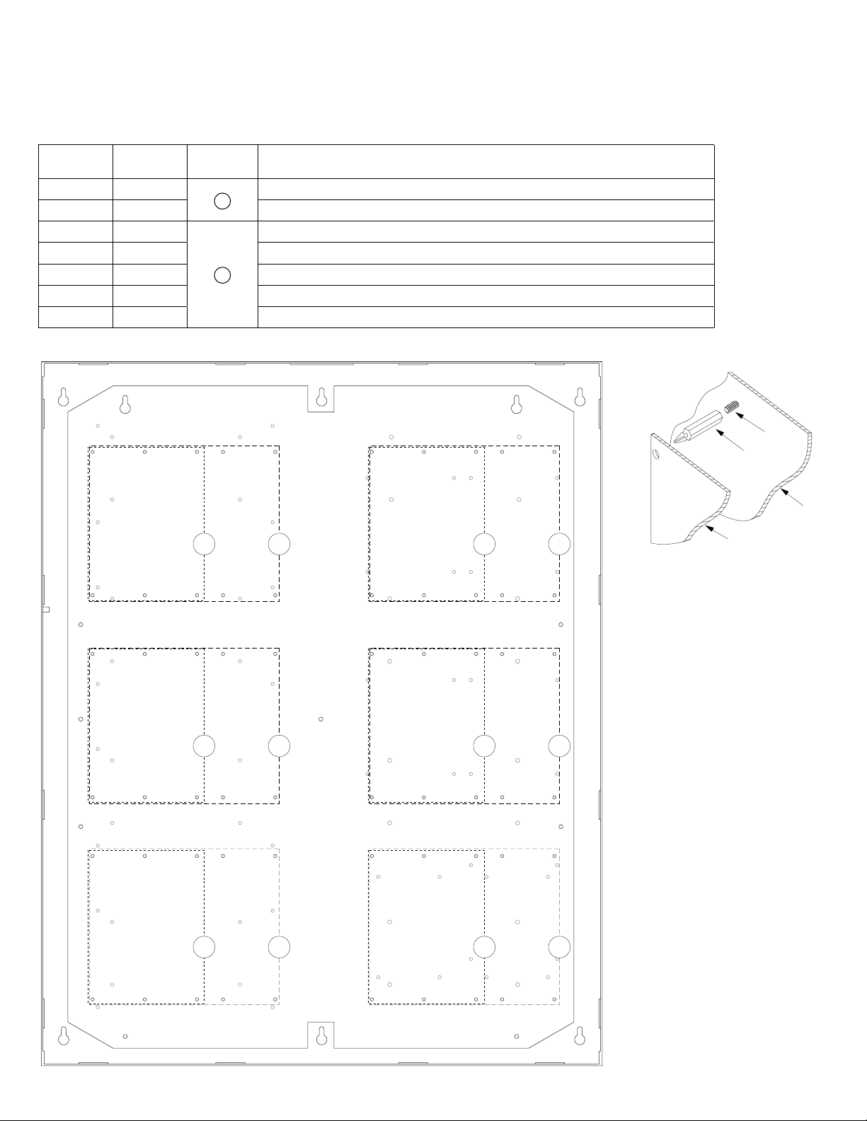
Installation Instructions for Mercury Access Controllers to TM2:
Access Controller
1. Fasten female/male standoffs onto metal pems configuration (A) (B) of back plane depending on the access controller (Fig. 2, pg. 3).
2. Position access controller module over corresponding standoffs and depress onto female/male standoffs (Fig. 2a, pg. 3).
3. Mount back plane to enclosure with hardware.
Access Controller Position Chart for the Following Models:
Mercury Lenel
EP2500 LNL-3300
MUX8 LNL-8000 12VDC 250mA max.
EP1502 LNL-2220
Pem
Mounting
A
Current Draw
12-24VDC 300mA max.
12-24VDC 500mA max.
EP4502 LNL-4420 12-24VDC 500mA max.
MR16IN LNL-1100 12-24VDC 350mA max. (12VDC @ 300mA nom., 24VDC @ 220mA nom.)
B
MR16OUT LNL-1200 12-24VDC 1100mA max. (12VDC @ 850mA nom., 24VDC @ 450mA nom.)
MR52 LNL-1320 12-24VDC 550mA max. (12VDC @ 450mA nom., 24VDC @ 270mA nom.)
Fig. 2
Fig. 2a
BA BA
Pem
Female/Male
Standoff
Backplane
Mercury
BA BA
BA BA
- 3 - Trove1M1 / TM1 / Trove2M2 / TM2
Page 4

Installation Instructions for Mercury Access Controllers to TM2:
1. Fasten female/male standoffs onto metal pems configuration (A) (B) of back plane depending on the access controller (Fig. 3, pg. 4).
2. Position access controller module over corresponding standoffs and depress onto female/male standoffs (Fig. 3a, pg. 4).
3. Mount back plane to enclosure with hardware.
Access Controller Position Chart for the Following Models:
Mercury Lenel
EP1501 LNL-2210
MR51e LNL-1300e 12VDC 1100mA max.
Pem
Mounting
A
Current Draw
12VDC 900mA max.
MR50 LNL-1300 B 12-24VDC 150mA max. (12VDC @ 110mA nom., 24VDC @ 60mA nom.)
Fig. 3
Fig. 3a
A A
Pem
Female/Male
Standoff
Backplane
Mercury
Access Controller
A A
A
BB
- 4 - Trove1M1 / TM1 / Trove2M2 / TM2
Page 5

Installation Instructions for Mercury Access Controllers to TMV2 (door back plane):
Access Controller
1. Fasten female/male standoffs onto metal pems configuration (A) (B) of back plane depending on the access controller (Fig. 4, pg. 5).
2. Position access controller module over corresponding standoffs and depress onto female/male standoffs (Fig. 4a, pg. 5).
3. Mount back plane to enclosure with hardware.
Access Controller Position Chart for the Following Models:
Mercury Lenel
EP2500 LNL-3300
MUX8 LNL-8000 12VDC 250mA max.
EP1502 LNL-2220
Pem
Mounting
A
Current Draw
12-24VDC 300mA max.
12-24VDC 500mA max.
EP4502 LNL-4420 12-24VDC 500mA max.
MR16IN LNL-1100 12-24VDC 350mA max. (12VDC @ 300mA nom., 24VDC @ 220mA nom.)
B
MR16OUT LNL-1200 12-24VDC 1100mA max. (12VDC @ 850mA nom., 24VDC @ 450mA nom.)
MR52 LNL-1320 12-24VDC 550mA max. (12VDC @ 450mA nom., 24VDC @ 270mA nom.)
Fig. 4
Fig. 4a
BA BA
Pem
Female/Male
Standoff
Backplane
Mercury
BA
BA
Trove1M1 / TM1 / Trove2M2 / TM2 - 5 -
BA
BA
Page 6

1.25”
(31.75mm)
1.5”
(38.09mm)
(114.3mm)
0.569”
(14.52mm)
4.5”
Trove1 Enclosure Dimensions (H x W x D approximate):
18” x 14.5” x 4.625” (457mm x 368mm x 118mm)
14.5”
(184.15mm)
0.5897”
(14.98mm)
7.25”
1.45”
(36.83mm)
(321.31mm)
13.0”
(330.2mm)
1.948”
(49.483mm)
1.25”
(31.75mm)
1.5”
(38.09mm)
8.5”
(215.9mm)
6.5”
(165.1mm)
18.0”
(457.2mm)
0.6012”
(15.27mm)
1.0958”
(27.83mm)
4.5”
(114.3mm)
4.5”
(114.3mm)
2.75”
(69.85mm)
8.5”
(215.9mm)
6.5”
(165.1mm)
1.115”
(28.32mm)
1.362”
(34.59mm)
1.25”
(31.75mm)
- 6 - Trove1M1 / TM1 / Trove2M2 / TM2
Page 7

1.25”
(
)
(
)
(
)
(
)
(
)
(31.75mm)
Trove2 Enclosure Dimensions (H x W x D approximate):
27.25” x 21.75” x 6.5” (692.15mm x 546.1mm x 165.1mm)
21.50”
(546.1mm)
2.00”
(50.8mm)
5.25”
(133.35mm)
3.50”
(88.9mm)
0.5625”
(14.29mm)
3.50”
(88.9mm)
(44.96mm)
2.415”
(61.34mm)
1.77”
5.25”
(133.35mm)
0.685”
(17.399mm)
Knockouts
1.125” (28.32mm)
0.885” (22.479mm)
6.25”
(158.75mm)
6.25”
(158.75mm)
1.25”
(31.75mm)
G
0.85”
(21.59mm)
1.5”
(38.1mm)
27.00”
(685.8mm)
19.80”
(502.92mm)
2.00”
(50.8mm)
6.75”
(171.45mm)
8.25”
(209.54mm)
8.00”
(203.2mm)
0.85”
(21.59mm)
2.00”
(50.8mm)
1.00”
(25.4mm)
1.25”
(31.75mm)
2.00”
50.8mm
Trove1M1 / TM1 / Trove2M2 / TM2 - 7 -
5.25”
133.35mm
7.00”
177.79mm
5.25”
133.35mm
2.00”
50.8mm
1.25”
(31.75mm)
Page 8

Notes:
Altronix is not responsible for any typographical errors.
140 58th Street, Brooklyn, New York 11220 USA, 718-567-8181, fax: 718-567-9056
web site: www.altronix.com, e-mail: info@altronix.com. Lifetime Warranty, Made in U.S.A.
IITrove1M1 / TM1 / Trove2M2 / TM2 I12Q
- 8 - Trove1M1 / TM1 / Trove2M2 / TM2
MEMBER
 Loading...