

Page 1

Access & Power Integration
Trove1HW1R
- Trove rack enclosure with Altronix/Honeywell backplane (THW1R)
Installation Guide
All registered trademarks are property of their respective owners. More than just power.™
Rev. THWR031119
Installing Company: _____________________ Service Rep. Name: __________________________________________
Address: ________________________________________________________ Phone #: _________________________
Page 2
Overview:
Altronix Trove1HW1R rack mount access & power integration solution accommodates various combinations of Honeywell boards with or
without Altronix power supplies and accessories for access systems.
Specifications:
Agency Listings:
• CE European Conformity.
Trove1HW1R
Trove1R rack mount enclosure with
THW1R Altronix/Honeywell backplane.
• 16 Gauge black enclosure with ample knockouts for
convenient access.
• Includes: tamper switch, cam lock and mounting hardware.
Modular 2U standard EIA 19” drawer with
extendable slides up to 48”.
• Dimensions (H x W x D): 3.25” x 19.0” x 26.5”
(82.6mm x 482.6mm x 673.1mm).
THW1R
Altronix/Honeywell backplane.
• 16 Gauge backplane.
• Dimensions (H x W x D): 18.5” x 15.25” x 0.3125”
(469.9mm x 387.4mm x 7.9mm).
Optional Accessories:
• RE2: Rack Mount Battery Enclosure accommodates up to four (4)
12VDC/7AH batteries
• WM5, WM25, WM100: Magnetic Cable Tie Mounts
(5, 25, 100 counts).
• LC3: 6 ft. three-wire line cord.
Backplane Accommodates a Combination of the Following:
Altronix:
• One (1) eFlow4NB, eFlow6NB, eFlow102NB, eFlow104NB,
ACMS8(CB), or ACM8(CB).
• Up to two (2) ACM4(CB), MOM5, PD4UL(CB), PD8UL(CB),
PDS8(CB), or VR6.
Hardware and Accessories:
Spacer | 5/16” Pan Head Screw | Lock Nut
Honeywell:
• Up to four (4) PRO32E1PS, PRO32IC, PRO32R2, PRO32IN,
PRO32OUT, PW6K2E2PS, PW6K1IC, PW6K1IN, PW6K1OUT,
PW6K1R2.
• One (1) PRO32E1PS or PW6K2E2PS.
- 2 - Trove1HW1R
Page 3
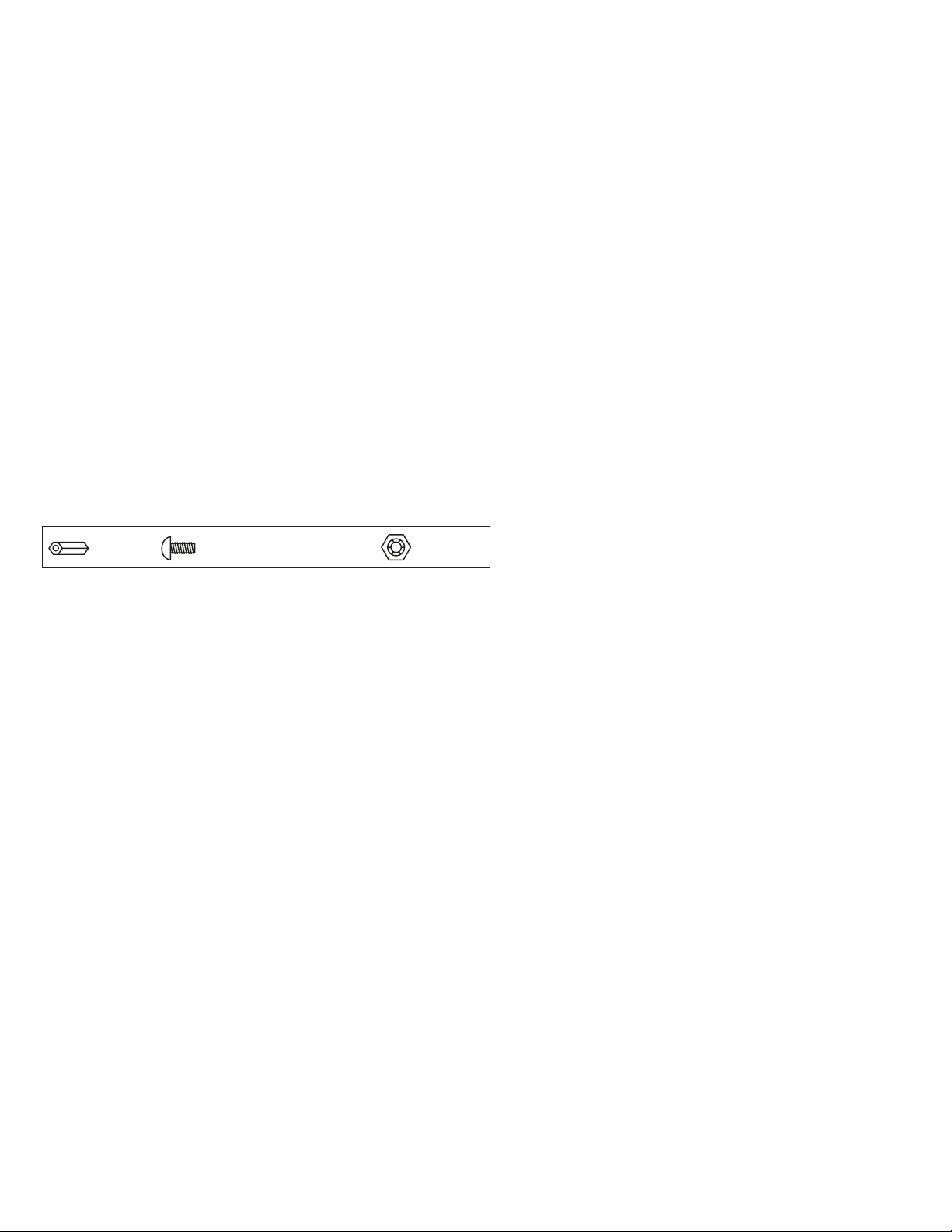
Assembling and Attaching Z Bracket Wire Management Accessory (included):
Altronix Trove Rack enclosures include Z Bracket, a convenient and reliable wire management accessory.
1. Carefully unpack Z Bracket. Do not discard hardware (included) (Fig. 1, pg. 3).
2. Attach arms to each other using bolts and lock nuts (Fig. 1a, pg. 3).
3. Attach the hinge brackets to the ends of arms using bolts and nuts positioning them as shown on Fig. 1b, pg. 3.
4. Make sure that all nuts are tightened.
Hardware (included):
Ten (10) bolts and eight (8) lock nuts
Fig. 1a
5. Attach the hinge bracket on the longer side of Z Bracket to the adjustable rail using bolts and lock nuts (included) (Fig. 2, 2a, pg. 3).
6. Attach the hinge bracket on the shorter side of Z Bracket to the rear of the rack enclosure using bolts (included).
Fig. 2
Fig. 1
Two (2)
Fig. 1b
Fig. 2a
Trove1HW1R - 3 -
Page 4

Installation Instructions for Trove1R:
Wiring methods shall be in accordance with the National Electrical Code/NFPA 70/ANSI, and with all local codes and authorities having
jurisdiction. Product is intended for indoor use only.
1. Remove backplane from enclosure prior to installing into rack cabinet (do not discard hardware).
2. In order to mount included UL Listed tamper switch (Altronix Model TS112 or equivalent), turn the enclosure upside down.
Punch out the knockout in designated location, on the back of the unit, from outside of the drawer (Fig. 3, pg. 4).
Insert the tamper switch into the knockout from outside of the drawer with the button facing outwards and spaded connectors inside
the drawer. Connect tamper switch wiring to the Access Control Panel input or the appropriate UL Listed reporting device.
To activate alarm signal open the rack drawer.
3. Slide the Trove rack enclosure into an open 2U location in the rack cabinet.
4. Utilizing proper fasteners attach front ears to the rack rails.
5. Attach the rear of the adjustable slides to the rear rails of the rack cabinet with the proper fasteners.
6. Make sure that all internal cofigurations (wiring, voltage selection, switch settings, etc.) are complete before mounting backplane back
into enclosure.
7. After all components are mounted on the backplane, attach it to the enclosure using included hardware.
Fig. 3
Back of the drawer,
viewed from outside.
Tamper Switch mounting location
- 4 - Trove1HW1R
Page 5
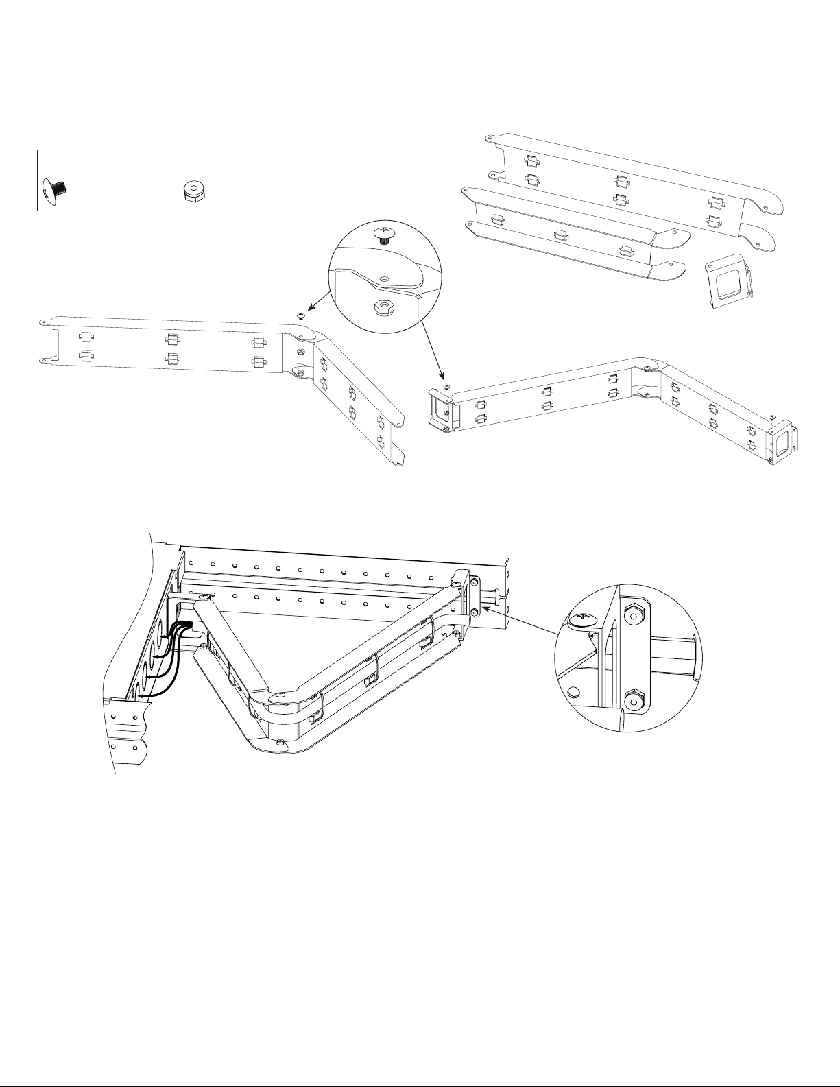
THW1R: Configuration of Altronix Power Supply and/or Sub-Assembly Boards
1. Fasten spacers onto metal pems configuration (A) or (B) of backplane depending on the power supply and/or Sub-Assembly (Fig. 4, pg. 5).
2. Position access controller module over corresponding spacers and fasten screws into spacers (Fig. 4a, pg. 5).
3. Mount backplane to enclosure with hardware.
Position Chart for the Following Models:
Altronix Power Supply/Charger or Sub-Assembly Pem Mounting
eFlow4NB, eFlow6NB, eFlow102NB, eFlow104NB, ACMS8(CB) or ACM8(CB) A
ACM4(CB), MOM5, PD4UL(CB), PD8UL(CB), PDS8(CB), or VR6 B
Fig. 4
Fig. 4a
Pan Head Screw
Power Supply or
Sub-Assembly
Metal
Spacer
Placement
for Altronix
Power
Supplies
A
Backplane
Spacer
Pem
B
B
Trove1HW1R - 5 -
Page 6
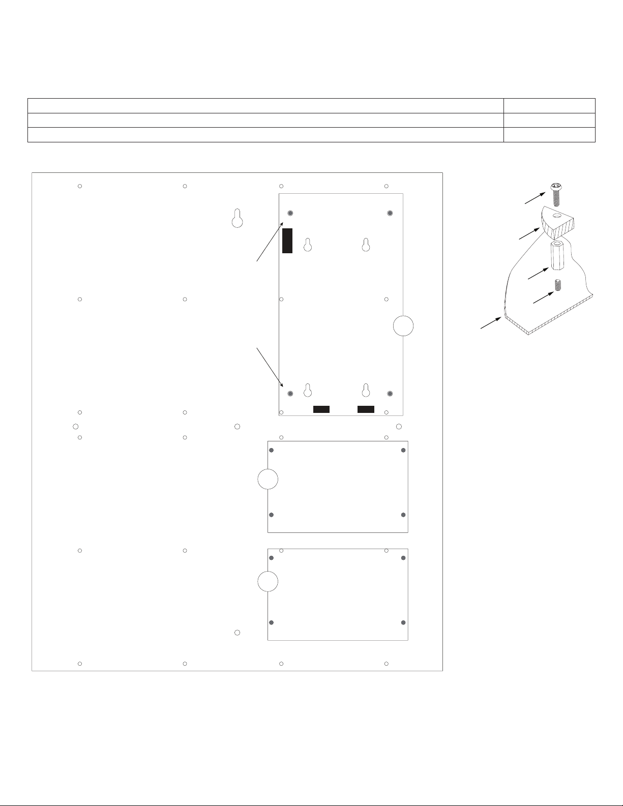
Installation Instructions for Honeywell PRO32E1PS or PW6K2E2PS to THW1R:
1. Install four (4) mounting screws approximately halfway into mounting holes in the power supply’s frame.
2. Position the power supply over four (4) keyholes (B) on THW1R.
3. Slide the power supply forward until secure. Tighten the mounting screws.
Installation Instructions for Honeywell Access Controllers to THW1R:
1. Fasten spacers (provided) into pem configuration (A) of backplane (Fig. 5, pg. 6).
2. Mount boards to spacers utilizing 5/16” pan head screws (provided) (Fig. 5a, pg. 6).
3. Mount backplane to enclosure with hardware.
Honeywell ProWatch/WinPak Power Supply or Access Controller
Position Chart for the Following Models:
Honeywell Board Pem Mounting
3200 Series or WIN-PAK Series A
PRO32E1PS or PW6K2E2PS B
Fig. 5
A A
B
Fig. 5a
Pan Head Screw
Power Supply or
Sub-Assembly
Spacer
Pem
Backplane
A A
- 6 - Trove1HW1R
Page 7

Notes:
Trove1HW1R - 7 -
Page 8

Trove1R Enclosure Dimensions (H x W x D):
3.25” x 19.0” x 26.5” (82.6mm x 482.6mm x 673.1mm). Shown with Z Bracket attached.
26.5”
673.1mm
2.4”
61mm
4.57”
116.1mm
1” (25.4mm)
11.175” (283.8mm)
0.55” (14mm)
R 1.27” (32.3mm)
0.1”
2.5mm
3.62”
92mm
1.5”
38.1mm
19” (482.6mm)
3.25”
82.3mm
Altronix is not responsible for any typographical errors.
140 58th Street, Brooklyn, New York 11220 USA | phone: 718-567-8181 | fax: 718-567-9056
web site: www.altronix.com | e-mail: info@altronix.com | Made in U.S.A.
IITrove1HW1R H21T
- 8 - Trove1HW1R
MEMBER
 Loading...