

Page 1

SIGNALING
Access & Power Integration
Trove1C1
- Trove1 enclosure with Altronix/CDVI backplane (TC1)
TC1
- Altronix/CDVI backplane only
Trove2CV2
- Trove2 enclosure with Altronix/CDVI backplane (TCV2)
TCV2
- Altronix/CDVI backplane only
Trove3CV3 (not evaluated by UL)
- Trove3 enclosure with Altronix/CDVI backplane (TCV3)
TCV3 (not evaluated by UL)
- Altronix/CDVI backplane only
Installation Guide
All registered trademarks are property of their respective owners. More than just power.™
Rev. TCDVI011117
Installing Company: _____________________ Service Rep. Name: __________________________________________
Address: ________________________________________________________ Phone #: _________________________
Page 2

Overview:
Edge of
Enclosure
to Access Control Panel
or U.L. Listed
Reporting Device
Enclosure
Honeywell
model # 112
Tamper Switch
or equivalent
(provided)
Trove1C1, Trove2CV2 and Trove3CV3 accommodate various combinations of CDVI boards with or without Altronix power supplies and
accessories for access control systems.
Specifications:
• 16 Gauge grey backplane and enclosure with ample knockouts for convenient access.
Trove1C1
Trove1 enclosure with
TC1 Altronix/CDVI backplane
• Includes: tamper switch, cam lock,
and mounting hardware.
Enclosure Dimensions (H x W x D):
18” x 14.5” x 4.625”
(457mm x 368mm x 118mm).
TC1
Altronix/CDVI backplane only
• Includes mounting hardware.
Dimensions (H x W x D):
16.625” x 12.5” x 0.3125”
(422.3mm x 317.5mm x 7.9mm).
TC1 accommodates a combination
of the following:
Altronix Modules:
• One (1) AL400ULXB2, AL600ULXB,
AL1012ULXB, AL1024ULXB2,
eFlow4NB, eFlow6NB, eFlow102NB or
eFlow104NB.
• One (1) ACM4(CB), MOM5, PD4UL(CB),
PD8UL(CB), PDS8(CB), VR6.
CDVI Modules:
• Four (4) A22NB modules.
Trove2CV2
Trove2 enclosure with
TCV2 Altronix/CDVI backplane
• Includes: tamper switch, cam lock,
and mounting hardware.
Enclosure Dimensions (H x W x D):
27.25” x 21.75” x 6.5”
(692.15mm x 552.5mm x 165.1mm).
TCV2
Altronix/CDVI backplane only
• Includes mounting hardware.
Dimensions (H x W x D):
25.375” x 19.375” x 0.3125”
(644.5mm x 482.6mm x 7.9mm).
TCV2 accommodates a combination
of the following:
Altronix Modules:
• Two (2) AL400ULXB2, AL600ULXB,
AL1012ULXB, AL1024ULXB2,
eFlow4NB, eFlow6NB, eFlow102NB or
eFlow104NB.
• One (1) ACM8(CB), or two (2) MOM5,
PD4UL(CB), PD8UL(CB), PDS8(CB),
VR6.
CDVI Modules:
• Five (5) A22NB modules.
Trove3CV3
Trove3 enclosure with
TCV3 Altronix/CDVI backplane
• Includes: two (2) tamper switches, cam
lock, and mounting hardware.
Enclosure Dimensions (H x W x D):
36.12” x 30.125” x 7.06”
(917.5mm x 768.1mm x 179.3mm).
TCV3
Altronix/CDVI backplane only
• Includes mounting hardware.
Dimensions (H x W x D):
34” x 28” x 0.3125”
(863.6mm x 711.2mm x 7.9mm).
TCV3 accommodates a combination
of the following:
Altronix Modules:
• Up to four (4) AL400ULXB2,
AL600ULXB, AL1012ULXB,
AL1024ULXB2, eFlow4NB, eFlow6NB,
eFlow102NB or eFlow104NB.
• Up to four (4) ACM8(CB), MOM5,
PD4UL(CB), PD8UL(CB), PDS8(CB),
VR6.
CDVI Modules:
• Ten (10) A22NB modules.
Installation Instructions for Trove1, Trove2, Trove3:
1. Remove backplane from enclosure prior to mounting (do not discard hardware).
2. Trove1C1 (Pg. 8):
Mark and predrill holes on the wall to line up with the top two keyholes in the enclosure. Install two upper fasteners and screws in
the wall with the screw heads protruding. Place the enclosure’s upper keyholes over the two upper screws; level and secure.
Mark the position of the lower two holes. Remove the enclosure. Drill the lower holes and install the two fasteners.
Place the enclosure’s upper keyholes over the two upper screws. Install the two lower screws and make sure to tighten all screws.
Trove2CV2 and Trove3CV3 (Pg. 10 and Pg. 12):
Mark and predrill holes on the wall to line up with the top three keyholes in the enclosure. Install three upper fasteners and screws in
the wall with the screw heads protruding. Place the enclosure’s upper keyholes over the three upper screws; level and secure.
Mark the position of the lower three holes. Remove the enclosure. Drill the lower holes and install the three fasteners.
Place the enclosure’s upper keyholes over the three upper screws. Install the three lower screws and make sure to tighten all screws.
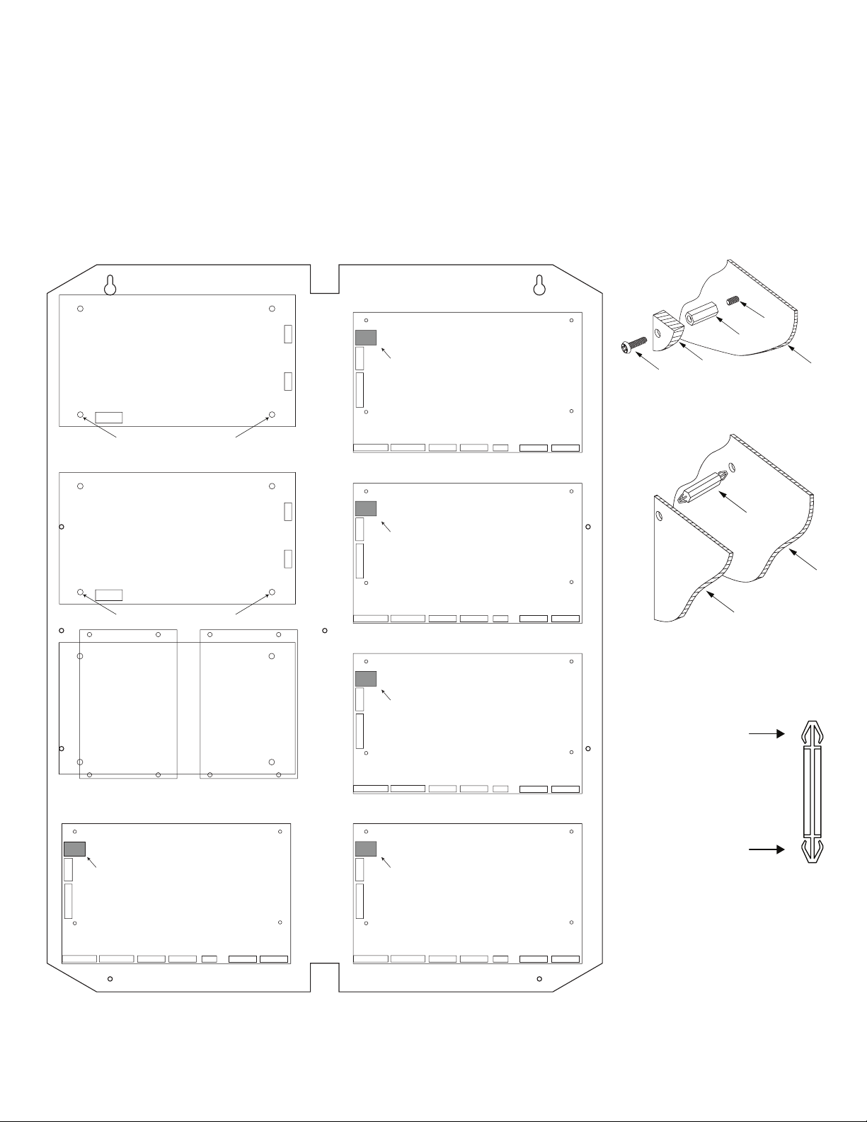
3. Mount included UL Listed tamper switch(es) (Honeywell Model 112 or equivalent)
in desired location, opposite hinge. Slide the tamper switch bracket onto the edge of
the enclosure approximately 2” from the right side (Fig. 1, pg. 2).
Connect tamper switch wiring to the Access Control Panel input or the appropriate
UL Listed reporting device. To activate alarm signal open the door of the enclosure.
4. Mount Altronix/CDVI modules to TC1, TCV2 or TCV3 backplane, refer to pages 3, 4, 5.
Fig. 1
- 2 - Trove / CDVI
Page 3

TC1: Configuration of Altronix Power Supply
Plastic Standoff
TC1/TCV2/TCV3 backplane
and/or Sub-Assembly Boards and CDVI Modules
1. Fasten standoffs (provided) to pems that match the hole pattern for Altronix Power Supply/Chargers or Altronix Sub-Assembly boards
(Fig. 2, pg. 3). Fasten metal standoffs in the correct locations to provide proper grounding, see below (Fig. 2, pg. 3).
2. Mount boards to standoffs utilizing 5/16” pan head screws (provided) (Fig. 2a, pg. 3).
3. Mount appropriate CDVI A22NB modules into the correct positions (Fig. 2, pg. 3) by postioning standoffs over appropriate holes on
the backplane and depress down on board to secure standoff to the backplane (Fig. 2, 2b, 2c, pg. 3).
Note: CDVI A22NB modules have one (1) RJ45 jack each. Please make sure that they are mounted correctly, as shown in Fig. 2 below.
4. Fasten TC1 backplane to Trove1 enclosure utilizing pan head screws (provided).
Fig. 2 - Trove1C1/TC1 Configurations
Metal
Standoff
Placement
Altronix
Power
Supply
Altronix
Sub-
Assembly
CDVI - A22NB CDVI - A22NBCDVI - A22NB
RJ45 Jack RJ45 Jack RJ45 Jack
RJ45 JackRJ45 JackRJ45 Jack
CDVI - A22NB CDVI - A22NBCDVI - A22NB
Fig. 2a
Fig. 2b
Fig. 2c
pre-mounted into
CDVI Atrium modules
Pem
Pan Head
Screw
Standoff
Altronix
Power Supply or
Sub-Assembly
Backplane
Standoff
Insert into
Backplane
CDVI - A22NB
Access Controller
Trove / CDVI - 3 -
Page 4
TCV2: Configuration of Altronix Power Supply
TC1/TCV2/TCV3 backplane
and/or Sub-Assembly Boards and CDVI Modules
1. Fasten standoffs (provided) to pems that match the hole pattern for Altronix Power Supply/Chargers or Altronix Sub-Assembly boards
(Fig. 3, pg. 4). Fasten metal standoffs in the correct locations to provide proper grounding, see below (Fig. 3, pg. 4).
Note: Altronix sub-assembly position can accommodate either one (1) ACM8/ACM8CB or two (2) PD4UL/PD4ULCB,
PD8UL/PD8ULCB or MOM5.
2. Mount boards to standoffs utilizing 5/16” pan head screws (provided) (Fig. 3a, pg. 4).
3. Mount appropriate CDVI A22NB modules into the correct positions (Fig. 3, pg. 4). by positioning standoffs over appropriate holes on
the backplane and depress down on board to secure standoff to the backplane (Fig. 3, 3b, 3c, pg. 4).
Note: CDVI A22NB modules have one (1) RJ45 jack each. Please make sure that they are mounted correctly, as shown in Fig. 3 below.
4. Fasten TCV2 backplane to Trove2 enclosure utilizing pan head screws (provided).
Fig. 3 - Trove2CV2/TCV2 Configurations
Fig. 3a
Pem
Altronix
Power Supply
RJ45 Jack
CDVI - A22NB
Pan Head
Screw
Standoff
Altronix
Power Supply or
Sub-Assembly
Backplane
Metal Standoff Placement
Altronix
Power Supply or
Sub-Assembly
Metal Standoff Placement
Altronix
RJ45 Jack
CDVI - A22NB
RJ45 Jack
Sub-Assembly
CDVI - A22NB
RJ45 Jack RJ45 Jack
Fig. 3b
Standoff
Backplane
CDVI - A22NB
Access Controller
Fig. 3c
Plastic Standoff
pre-mounted into
CDVI Atrium modules
Insert into
CDVI - A22NBCDVI - A22NB
- 4 - Trove / CDVI
Page 5

TCV3: Configuration of Altronix Power Supply
Plastic Standoff
TC1/TCV2/TCV3 backplane
and/or Sub-Assembly Boards and CDVI Modules
1. Fasten standoffs (provided) to pems that match the hole pattern for Altronix Power Supply/Chargers or Altronix Sub-Assembly boards
(Fig. 4, pg. 5). Fasten metal standoffs in the correct locations to provide proper grounding, see below (Fig. 4, pg. 5).
Note: Altronix sub-assembly positions can accommodate two (2) PD4UL/PD4ULCB, PD8UL/PD8ULCB or MOM5.
2. Mount boards to standoffs utilizing 5/16” pan head screws (provided) (Fig. 4a, pg. 5).
3. Mount appropriate CDVI A22NB modules into the correct positions (Fig. 4, pg. 5). by positioning standoffs over appropriate holes on
the backplane and depress down on board to secure standoff to the backplane (Fig. 4, 4b, 4c, pg. 5).
Note: CDVI A22NB modules have one (1) RJ45 jack each. Please make sure that they are mounted correctly, as shown in Fig. 4 below.
4. TCV3 backplane installation: refer to note below drawing and Fig. 4d, pg. 5.
5. Fasten TCV3 backplane to Trove3 enclosure utilizing pan head screws (provided).
Fig. 4 - Trove3CV3/TCV3 Configurations
Altronix
Power Supply
Metal
Standoff
Placement
Altronix
Power Supply
Metal
Standoff
Placement
Altronix
Sub-Assembly
RJ45 Jack
CDVI - A22NB
RJ45 Jack
CDVI - A22NB
RJ45 Jack
CDVI - A22NB
RJ45 Jack
CDVI - A22NB
RJ45 Jack
CDVI - A22NB
RJ45 Jack
CDVI - A22NB
Fig. 4a
Pan Head
Screw
Fig. 4b
Standoff
Altronix
Power Supply or
Sub-Assembly
Standoff
CDVI - A22NB
Access Controller
Pem
Backplane
Backplane
Fig. 4c
Altronix
Sub-Assembly
RJ45 Jack
CDVI - A22NB
RJ45 Jack
CDVI - A22NB
pre-mounted into
CDVI Atrium modules
Altronix
Sub-Assembly
Insert into
RJ45 Jack
CDVI - A22NB
Altronix
Sub-Assembly
Note: TCV3 bumper installation.
Prior to mounting TCV3 install rubber bumpers
(included) to the back of backplane, one (1) on
top and one (1) on bottom, approximately 1”
from the cutouts (Fig. 4d, pg. 5).
Bumpers are pre-installed in Trove3CV3
Trove / CDVI - 5 -
RJ45 Jack
CDVI - A22NB
Fig. 4d
Rubber
Bumper
Cutout
Back of
Backplane
Page 6

Notes:
- 6 - Trove / CDVI
Page 7

TC1 Dimensions
(
)
16.625” x 12.5” x 0.3125” (422.3mm x 317.5mm x 7.9mm)
12.5”
(317.5mm)
0.5” (12.7mm)
8.15”
(207mm)
16.625”
(422.3mm)
15.65”
(397.5mm)
0.5” (12.7mm)
6.25”
158.75mm
Trove / CDVI - 7 -
Page 8

1.25”
(31.75mm)
1.5”
(38.09mm)
(114.3mm)
0.569”
(14.52mm)
4.5”
Trove1C1 Enclosure Dimensions (H x W x D):
18” x 14.5” x 4.625” (457mm x 368mm x 118mm)
14.5”
(184.15mm)
0.5897”
(14.98mm)
7.25”
1.45”
(36.83mm)
(321.31mm)
13.0”
(330.2mm)
1.948”
(49.483mm)
1.25”
(31.75mm)
1.5”
(38.09mm)
8.5”
(215.9mm)
6.5”
(165.1mm)
18.0”
(457.2mm)
0.6012”
(15.27mm)
1.0958”
(27.83mm)
4.5”
(114.3mm)
4.5”
(114.3mm)
2.75”
(69.85mm)
8.5”
(215.9mm)
6.5”
(165.1mm)
1.115”
(28.32mm)
1.362”
(34.59mm)
1.25”
(31.75mm)
- 8 - Trove / CDVI
Page 9

24.95” (633.7mm)
TCV2 Dimensions
25.375” x 19.375” x 0.3125” (644.5mm x 482.6mm x 7.9mm).
19.375”
(482.6mm)
7.5”
(190.5mm)
7.5”
(190.5mm)
16.245” (412.6mm)
12.62” (320.6mm)
8.5” (215.8mm)
0.156”
( 3.96mm)
25.375”
(644.5mm)
12.62”
(320.6mm)
1.0”
(25.4mm)
0.45”
(11.4mm)
7.5”
(190.5mm)
Trove / CDVI - 9 -
1.0”
(25.4mm)
7.5”
(190.5mm)
Page 10

1.25”
(
)
(
)
(
)
(
)
(
)
(31.75mm)
Trove2CV2 Enclosure Dimensions (H x W x D):
27.25” x 21.75” x 6.5” (692.15mm x 552.5mm x 165.1mm)
21.50”
(546.1mm)
2.00”
(50.8mm)
5.25”
(133.35mm)
3.50”
(88.9mm)
0.5625”
(14.29mm)
3.50”
(88.9mm)
(44.96mm)
2.415”
(61.34mm)
1.77”
5.25”
(133.35mm)
0.685”
(17.399mm)
Knockouts
1.125” (28.32mm)
0.885” (22.479mm)
6.25”
(158.75mm)
6.25”
(158.75mm)
1.25”
(31.75mm)
G
0.85”
(21.59mm)
1.5”
(38.1mm)
27.00”
(685.8mm)
19.80”
(502.92mm)
2.00”
(50.8mm)
6.75”
(171.45mm)
8.25”
(209.54mm)
(203.2mm)
0.85”
(21.59mm)
(50.8mm)
1.00”
(25.4mm)
1.25”
(31.75mm)
2.00”
50.8mm
- 10 - Trove / CDVI
5.25”
133.35mm
7.00”
177.79mm
5.25”
133.35mm
2.00”
50.8mm
1.25”
(31.75mm)
8.00”
2.00”
Page 11

8.55” (217.2mm)
TCV3 Dimensions
34” x 28” x 0.3125” (863.6mm x 711.2mm x 7.9mm)
28” (711.2mm)
27” (685.8mm)
23” (584.2mm)
6.5” (165.1mm)
11.5” (292.1mm)
34” (863.6mm)
11.5” (292.1mm)
Trove / CDVI - 11 -
Page 12

Trove3CV3 Enclosure Dimensions (H x W x D approximate):
(50.8mm)
(222.3mm)
(222.3mm)
(219mm)
2.00”
7.12”
9.5”
9.5”
(273.1mm)
(273.1mm)
(269.8mm)
(917.5mm)
36.12” x 30.125” x 7.06” (917.5mm x 768.1mm x 179.3mm)
2.00”
(50.8mm)
10.75”
10.62”
1.25”
(31.8mm)
G
G
1.25”
(31.75mm)
1.10”
(27.9mm)
(50.8mm)
1.07”
(27.2mm)
33.63”
(854.20mm)
(222.25mm)
14.01”
(355.9mm)
(241.3mm)
30.12”
(768.1mm)
(241.3mm)
(45.21mm)
14.01”
(355.9mm)
1.78”
1.55”
(39.37mm)
2.00”
(50.8mm)
10.75”
(273.1mm)
10.62”
(269.8mm)
36.12”
10.75”
1.25”
(31.8mm)
2.00”
8.75”
8.62”
8.75”
7.06”
(179.3mm)
10.75”
(273.1mm)
1.25”
(31.8mm)
Altronix is not responsible for any typographical errors.
140 58th Street, Brooklyn, New York 11220 USA | phone: 718-567-8181 | fax: 718-567-9056
web site: www.altronix.com | e-mail: info@altronix.com | Made in U.S.A.
IITrove / CDVI I10R
- 12 - Trove / CDVI
MEMBER
 Loading...