

Page 1

Edge of
Enclosure
to Access Control Panel
or U.L. Listed
Reporting Device
Enclosure
Honeywell
model # 112
Tamper Switch
or equivalent
(provided)
Snap On Standoff
Access & Power Integration
TM400
- Compact enclosure for Mercury boards
Installation Guide
Overview:
TM400 accommodates various combinations of select Mercury boards for access systems.
TM400_Rev. 121317
Specifications:
• 16 Gauge grey enclosure with ample knockouts for convenient access.
Enclosure Dimensions (H x W x D): 15.5” x 12.0” x 4.5” (393.7mm x 304.8mm x 114.3mm).
• Includes: tamper switch, cam lock and mounting hardware.
Enclosure accommodates a combination of the following:
• Up to three (3) MR50.
• One (1) EP1501 or MR51e.
• One (1) EP4502, EP1502, MR52, MR16IN, or MR16OUT.
Installation Instructions:
Wiring methods shall be in accordance with the National Electrical Code/NFPA 70/ANSI, and with all local codes and authorities having
jurisdiction. Product is intended for indoor use only.
1. Mark and predrill holes on the wall to line up with the top two keyholes in the enclosure. Install two upper fasteners and screws in
the wall with the screw heads protruding. Place the enclosure’s upper keyholes over the two upper screws; level and secure.
Mark the position of the lower two holes. Remove the enclosure. Drill the lower holes and install the two fasteners.
Place the enclosure’s upper keyholes over the two upper screws.
Install the two lower screws and make sure to tighten all screws.
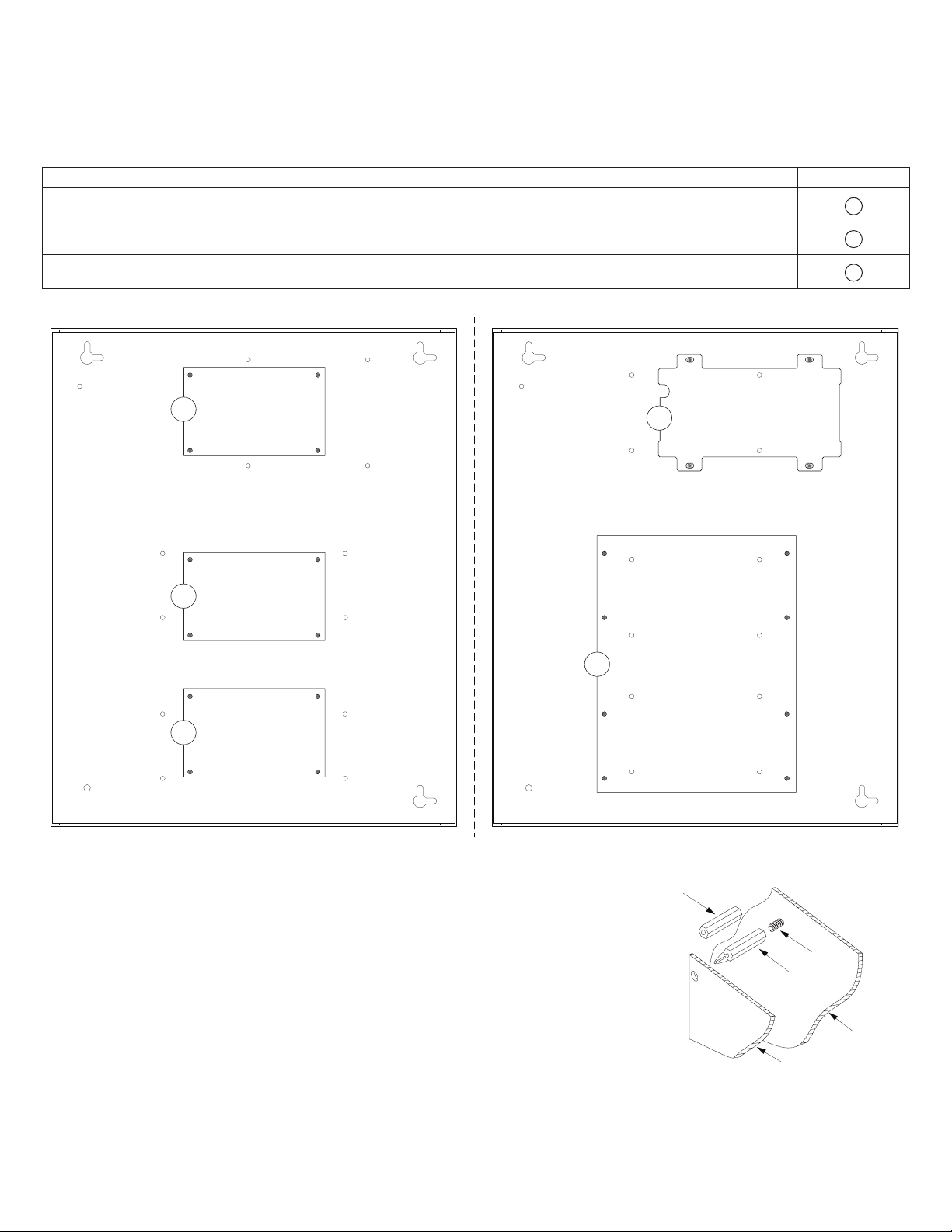
2. Mount included UL Listed tamper switch (Honeywell Model 112 or equivalent) in
desired location, opposite hinge. Slide the tamper switch bracket onto the edge of the
enclosure approximately 2” from the right side (Fig. 1, pg. 1). Connect tamper switch
wiring to the Access Control Panel input or the appropriate UL Listed reporting device.
To activate alarm signal open the door of the enclosure.
3. Mount Mercury boards to enclosure, refer to page 2.
Fig. 1
Hardware:
Standoff
5/16” Pan Head Screw
Page 2
Installation Instructions for Sub-Assemblies to TM400:
Ground
Lug
Ground
Lug
A
B
A
A
C
N
y
1. Fasten nylon or snap on standoffs onto metal pems configuration (A), (B) or (C) of enclosure depending on the
Mercury board (Fig. 2, pg. 2).
2. Position Mercury board over corresponding standoffs and secure board into enclosure with four (4) pan head screws
or depressing board onto standoffs supplied (Fig. 2, 2a, pg. 2).
Access Controller Position Chart for the Following Models:
Access Controller Pem Mounting
MR50 A
EP1501, MR51e B
EP4502, EP1502, MR52, MR16IN, MR16OUT, C
Fig. 2 - Mercury configurations
ylon
Standoff
Snap on
Standoff
Sub-Assembl
- 2 - TM400
Fig. 2a
Pem
Back of TM400
Page 3
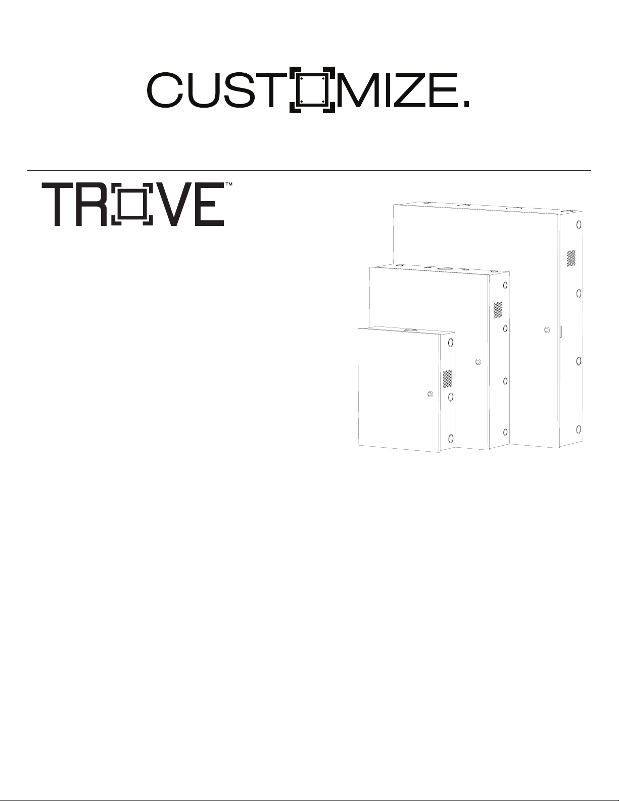
Access and power integration
Our Trove™ access and power integration solution lets you easily combine
Altronix power with access controllers and accessories available from the
industry’s leading manufacturers. A variety of backplanes offer a wide range
of scalable access and power configurations. This solution simplifies board
layout and wire management, while reducing installation and labor costs.
Customize your access control with Trove™.
Trove3
Trove2
• Easily combine Altronix power with access controllers and
accessories available from the industry’s leading manufacturers.
• Simplifies board layout and wire management.
• Reduces installation time and labor costs.
• Enclosures and backplanes sold separately.
• Optional door backplane (TMV2) accommodates Mercury and HID VertX.
Trove1:
Enclosure Dimensions: 18”H x 14.5”W x 4.625”D
Accommodates up to two (2) 12VDC/7AH batteries
Backplane Dimensions: 16.625”H x 12.5”W x 0.3125”D
Trove2:
Enclosure Dimensions: 27.25”H x 21.5”W x 6.5”D
Accommodates up to two (2) 12VDC/12AH batteries
Backplane Dimensions: 25.375”H x 19.375”W x 0.3125”D
Trove3:
Enclosure Dimensions: 36.12”H x 30.125”W x 7.06”D
Accommodates up to four (4) 12VDC/12AH batteries
Backplane Dimensions: 34”H x 28”W x 0.3125”D
Trove1
Visit www.altronix.com for the list of Trove supported manufacturers
TM400 - 3 -
Page 4

Enclosure Dimensions (H x W x D):
15.5” x 12.0” x 4.5” (393.7mm x 304.8mm x 114.3mm)
1.5”
(38.1mm)
2.0”
(50.8mm)
1.25”
(31.75mm)
4.5”
(114.3mm)
0.91”
(23.114mm)
1.5”
(38.1mm)
1.1”
(27.94mm)
4.615”
(117.22mm)
12.23”
(310.64mm)
4.615”
(117.22mm)
1.5”
(38.1mm)
1.1”
(27.94mm)
1.75”
(44.45mm)
0.91”
(23.114mm)
(393.7mm)
1.375”
(34.925mm)
1.125”
(28.575mm)
15.5”
4.5”
(114.3mm)
1.25”
(31.75mm)
1.5”
(38.1mm)
2.0”
(50.8mm)
5.0”
(127.0mm)
1.25”
(31.75mm)
1.5”
(38.1mm)
4.615”
(117.22mm)
4.615”
(117.22mm)
1.1”
(27.94mm)
1.5”
(38.1mm)
0.79”
(20.06mm)
1.75”
(44.45mm)
1.25”
(31.75mm)
5.0”
(127.0mm)
Altronix is not responsible for any typographical errors.
140 58th Street, Brooklyn, New York 11220 USA | phone: 718-567-8181 | fax: 718-567-9056
web site: www.altronix.com | e-mail: info@altronix.com | Made in U.S.A.
IITM400 I10R
MEMBER
- 4 - TM400
 Loading...