

Page 1

SIGNALING
Access & Power Integration
Trove2KS2
- Trove2 enclosure with Altronix/Keri Systems backplane (TKS2)
TKS2
- Altronix/Keri Systems backplane only
Installation Guide
All registered trademarks are property of their respective owners. More than just power.™
TKS2_Rev. 060419
Installing Company: _____________________ Service Rep. Name: __________________________________________
Address: ________________________________________________________ Phone #: _________________________
Page 2

Overview:
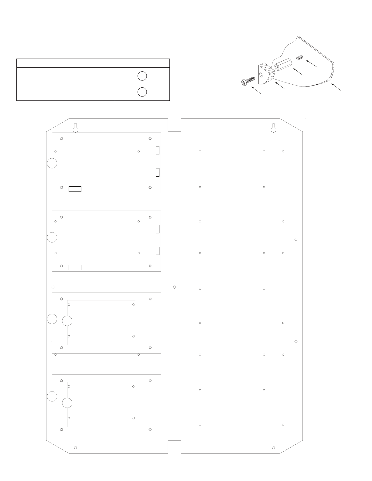
Tamper Switch
(provided)
To Access Control Panel or
UL Listed Reporting Device
Edge of
Enclosure
Enclosure
Trove2KS2 accommodates various combinations of Keri Systems boards with or without Altronix power supplies and accessories for
access systems.
Specifications:
Trove2KS2
- Trove2 enclosure with TKS2 Altronix/Keri Systems backplane.
• Includes: tamper switch, cam lock, mounting hardware.
• 16 Gauge enclosure with ample knockouts for convenient access.
Enclosure Dimensions (H x W x D): 27.25” x 21.75” x 6.5” (692.2mm x 552.5mm x 165.1mm).
Accommodates up to four (4) 12VDC/7AH batteries.
TKS2
- TKS2 Altronix/Keri Systems backplane.
• 16 Gauge backplane.
• Includes mounting hardware.
Dimensions (H x W x D): 25.375” x 19.375” x 0.3125” (644.6mm x 492.1mm x 7.9mm).
TKS2 accommodates a combination of the following:
Altronix:
• Up to four (4) AL400ULXB2, AL600ULXB, AL1012ULXB, AL1024ULXB2, eFlow4NB, eFlow6NB, eFlow102NB, or eFlow104NB.
• Two (2) PDS8(CB), VR6, ACM8(CB), ACMS8(CB), MOM5, PD4UL(CB), PD8UL(CB), or ACM4(CB).
Keri Systems:
• Six (6) NXT-2D-MSCNE, NXT-4D-MSCNE or three (3) NXT-4x4NE, or any combination of above.
Agency Listings:
• UL 294 - 6th edition: Line Security I, Destructive Attack I, Endurance IV, Stand-by Power II*.
*Stand-by Power Level I if no battery is supplied.
• This Class B digital apparatus complies with Canadian ICES-003.
Cet appareil numérique de la classe B est conforme á la norme NMB-003 du Canada.
• CE European Conformity.
Installation Instructions:
Wiring methods shall be in accordance with the National Electrical Code/NFPA 70/ANSI, and with all local codes and authorities having
jurisdiction. Product is intended for indoor use only.
1. Remove backplane from enclosure. Do not discard hardware.
2. Mark and predrill holes in the wall to line up with the top three keyholes in the enclosure. Install three upper fasteners and screws
in the wall with the screw heads protruding. Place the enclosure’s upper keyholes over the three upper screws; level and secure.
Mark the position of the lower three holes. Remove the enclosure. Drill the lower holes and install the three fasteners.
Place the enclosure’s upper keyholes over the three upper screws. Install the three lower screws and make sure to tighten all screws.
3. Mount included UL Listed tamper switch (Altronix Model TS112 or equivalent)
in desired location, opposite hinge. Slide the tamper switch bracket onto the edge of the
enclosure approximately 2” from the right side (Fig. 1, pg. 2). Connect tamper switch
wiring to the Access Control Panel input or the appropriate UL Listed reporting device.
To activate alarm signal open the door of the enclosure.
4. Mount Altronix/Keri Systems boards to backplanee, refer to pages 3, 4.
Fig. 1
- 2 - TroveKS
Page 3
Installation Instructions for Altronix Power Supplies and Sub-Assemblies to TKS2:
1. Fasten spacers (provided) into pem configuration (A) or (B) of backplane (Fig. 2, pg. 3).
2. Mount boards to spacers utilizing 5/16” pan head screws (provided) (Fig. 2a, pg. 3).
3. Mount backplane to enclosure with hardware.
Access Controller Position Chart for the Following Models:
Altronix Board Pem Mounting
Altronix Power Supply or
Sub-Assembly
A
Spacer
Fig. 2a
Pem
Altronix Sub-Assembly B
Fig. 2
A
A
Pan Head
Screw
Altronix
Power Supply or
Sub-Assembly
Backplane
A
B
A
B
TroveKS - 3 -
Page 4

Installation Instructions for Keri Systems Boards to TKS2:
1. Fasten spacers (provided) into pem configuration (A) or (B) of backplane (Fig. 3, pg. 4).
2. Mount boards to spacers utilizing 5/16” pan head screws (provided) (Fig. 3a, pg. 4).
Note: Keri Systems NXT-2D-MSCNE and NXT-4D-MSCNE boards have one (1) RJ45 jack each.
Please make sure that they are mounted correctly, as shown in Fig. 3 below.
3. Mount backplane to enclosure with hardware.
If use of NXTWI or NXTRM3 expansion boards is desired, there is no need to remove
NXT-2D-MSCNE, NXT-4D-MSCNE or NXT-4X4NE from the TKS2.
Access Controller Position Chart for the Following Models:
Keri Systems Board Pem Mounting
NXT-2D-MSCNE, NXT-4D-MSCNE A
NXT-4X4NE B
Fig. 3
Pan Head
Screw
Keri Systems
Board
B
Fig. 3a
Pem
Spacer
Backplane
RJ45 Jack
RJ45 Jack
RJ45 Jack
A
A
B
RJ45 Jack
A
A
B
RJ45 Jack
A
- 4 - TroveKS
RJ45 Jack
A
Page 5

eFlow Power Supply/Chargers can be Controlled and Monitored while
Reporting Power/Diagnostics from Anywhere over the Network...
LINQ2 - Network Communication Module
LINQ2 provides remote IP access to real-time data from eFlow power supply/chargers to help keep
systems up and running at optimal levels. It facilitates fast and easy installation and set-up, minimizes system downtime, and eliminates unnecessary service calls, which helps reduce Total Cost
of Ownership (TCO) - as well as creating a new source of Recurring Monthly Revenue (RMR).
LINQ2
Features:
- UL Listed in the U.S. and Canada.
- Local or remote control of up to (2) two Altronix eFlow power output(s) via LAN and/or WAN.
- Monitor real time diagnostics: DC output voltage, output current, AC & battery status/service, input trigger state change,
output state change and unit temperature.
- Access control and user managment: Restrict read/write, Restrict users to specific resources
- Two (2) integral network controlled Form “C” Relays.
- Three (3) programmable input triggers: Control relays and power supplies via external hardware sources.
- Email and Windows Dashboard notifications
- Event log tracks history.
- Secure Socket Layer (SSL).
- Programmable via USB or web browser - includes operating software and 6 ft. USB cable.
LINQ2 Mounts Inside any Trove Enclosure
LINQ2 Module
Network Connection:
Installation, Programming
and Monitoring
Altronix eFlow
Power Supply
TroveKS - 5 -
Page 6

Notes:
- 6 - TroveKS
Page 7

0.45” (11.4mm)0.45” (11.4mm)
TKS2 Dimensions (H x W x D):
25.375” x 19.375” x 0.3125” (644.6mm x 492.1mm x 7.9mm)
19.375” (492.1mm)
2.2” (55.9mm) 2.2” (55.9mm)
25.375” (644.6mm)
0.156”
( 3.96mm)
16.25” (412.8mm)
12.625” (320.7mm)
8.5” (215.9mm)
1.0” (25.4mm)
1.0” (25.4mm)
7.5” (190.5mm) 7.5” (190.5mm)
9.2” (233.7mm) 9.2” (233.7mm)
TroveKS - 7 -
Page 8

6.25” (158.8mm)
1.25” (31.8mm)
Trove2KS2 Enclosure Dimensions (H x W x D approximate):
27.25” x 21.75” x 6.5” (692.2mm x 552.5mm x 165.1mm)
21.50” (546.1mm)
2.00” (50.8mm) 2.00” (50.8mm)
1.25”
(31.8mm)
5.25” (133.35mm)
0.5625” (14.3mm)
3.5”(88.9mm) 3.5”(88.9mm)
(45mm)
2.415” (61.3mm)
1.5”
(38.1mm)
19.80” (502.9mm)
1.77”
5.25” (133.35mm)
0.685” (17.4mm)
Knockouts
1.125” (28.3mm)
0.885” (22.5mm)
6.25” (158.8mm)
2.00” (50.8mm)
6.75” (171.5mm)8.25” (209.5mm)
1.00” (25.4mm)
2.00” (50.8mm)
27” (685.8mm)
0.85” (21.6mm)
5.25” (133.4mm) 5.25” (133.4mm)7.00” (177.8mm)
8.00” (203.2mm)
2.00” (50.8mm)
1.25” (31.8mm)
1.25” (31.8mm)
2.00” (50.8mm)
Altronix is not responsible for any typographical errors.
140 58th Street, Brooklyn, New York 11220 USA | phone: 718-567-8181 | fax: 718-567-9056
web site: www.altronix.com | e-mail: info@altronix.com | Made in U.S.A.
IITroveKS K04S
- 8 - TroveKS
MEMBER
 Loading...