

Page 1

Access & Power Integration
TDMD2
- DMP door backplane for Trove2 and Trove3
Installation Guide
All registered trademarks are property of their respective owners. More than just power.™
Rev. TDMD2062119
Installing Company: _____________________ Service Rep. Name: __________________________________________
Address: ________________________________________________________ Phone #: _________________________
Page 2
DMP
714-8 0r 714-16
DMP
714-8 0r 714-16
DMP
714-8 0r 714-16
DMP
XR150 orXR550
Bracket
Screw
Step 3
Overview:
TDMD2 accommodates a combination of the following DMP boards: one (1) XR150 or XR550 board and up to three (3) multi-zone 714
expansion boards for up to forty-eight (48) zones.
Specifications:
• 16 Gauge backplane.
Dimensions (H x W x D): 23.75” x 18.125” x 0.3125” (603.3mm x 460.3mm x 7.9mm).
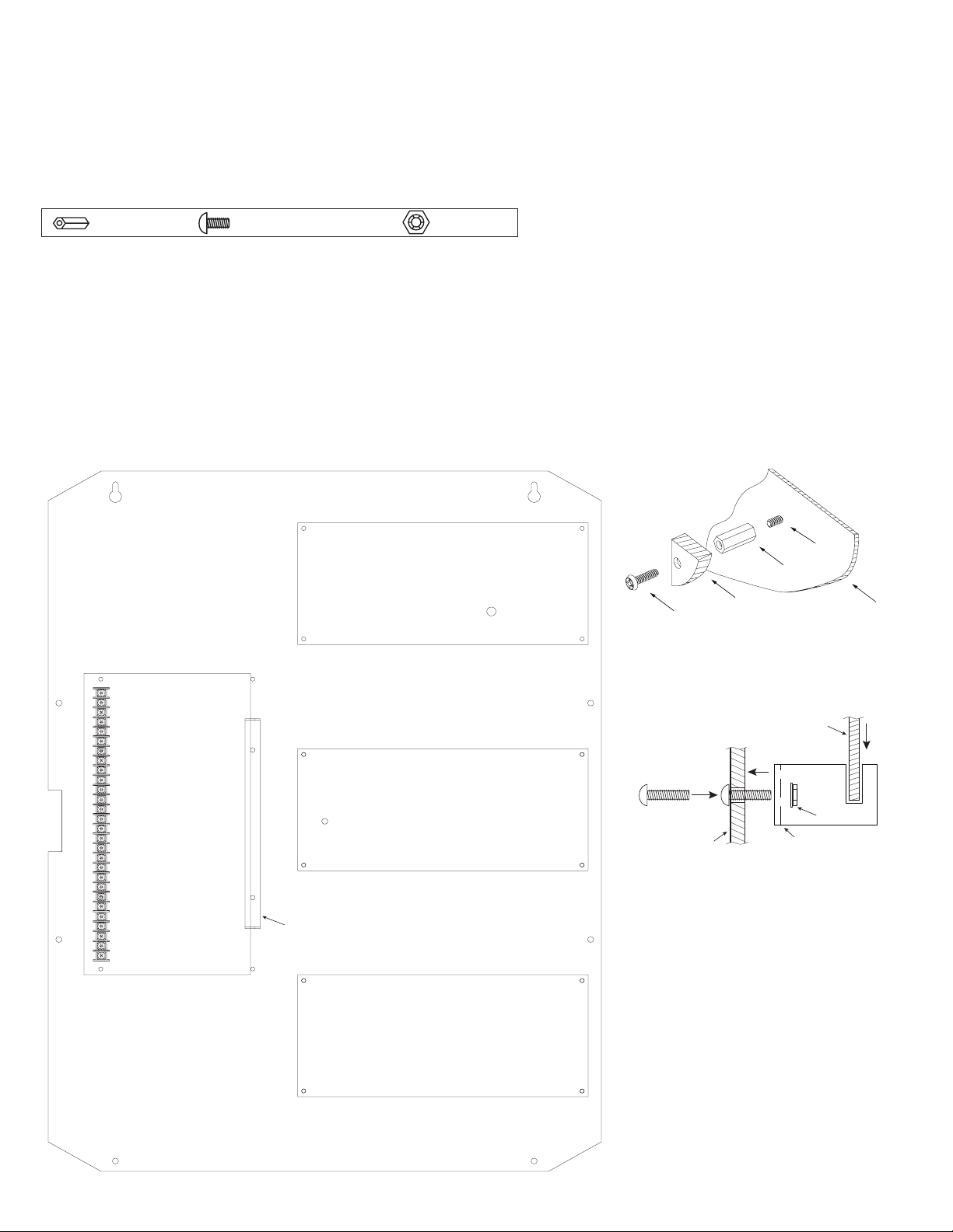
Hardware:
Nylon Spacer | 5/16” Pan Head Screw | Lock Nut
TDMD2: Configuration of DMP Boards:
1. Mounting 714 expansion boards:
a. Fasten spacers (provided) into a corresponding pem configuration of backplane (Fig. 1, pg. 2).
b. Mount boards to spacers utilizing 5/16” pan head screws (provided) (Fig. 1a, pg. 2).
2. Mounting XR150 or XR550 board utilizing a bracket (provided):
a. Push two (2) pan head screws (provided) through the corresponding holes from the back of the backplane (Fig. 1b, pg. 2, Step 1).
b. Mount bracket with slits to the left on screws and secure it with two (2) lock nuts (provided) (Fig. 1b, pg. 2, Step 2).
c. Fasten two (2) spacers (provided) onto the mounting pems.
d. Orient DMP XR150 or XR550 so the terminal block is to the left. Slide the opposite edge of the board into the bracket’s slits
(Fig. 1b, pg. 2, Step 3) and secure the board to spacers with two (2) pan head screws (provided).
3. Mount backplane to enclosure’s door with hardware.
Fig. 1
Fig. 1a
Pan Head
Step 1Step 2
Pan Head Screw
Back of TDMD2
DMP Board
XR150 or XR550
Pem
Spacer
Backplane
Fig. 1b
Lock Nut
XR150 or XR550
Mounting Bracket
- 2 - TDMD2 - DMP Door Backplane
Page 3

Notes:
TDMD2 - DMP Door Backplane - 3 -
Page 4

23.75” x 18.125” x 0.3125” (603.3mm x 460.3mm x 7.9mm)
0.156” ( 4mm)
TDMD2 Backplane Dimensions (H x W x D):
18.125” (460.3mm)
13.7” (350mm)
7.4” (188mm)8” (203.2mm)7.85” (199.4mm)
0.45” (11.4mm)
23.75” (603.3mm)
2.075”
(52.7mm)
10.82” (274.8mm)
8.7”
(221mm)
8.7”
(221mm)
11.8”
(299.7mm)
7.5” (190.5mm)
13.7” (350mm)
Altronix is not responsible for any typographical errors.
140 58th Street, Brooklyn, New York 11220 USA | phone: 718-567-8181 | fax: 718-567-9056
web site: www.altronix.com | e-mail: info@altronix.com | Made in U.S.A.
IITDMD2 F21S
- 4 - TDMD2 - DMP Door Backplane
MEMBER
 Loading...