

Page 1
Edge of
Enclosure
to Access Control Panel
or U.L. Listed
Reporting Device
Enclosure
Honeywell
model # 112
Tamper Switch
or equivalent
(provided)
Rev. 062216
Installation Guide
Versatile Access Power and Integration Enclosures
Trove2AM2 TAM2
- Trove2 enclosure with - Altronix/AMAG backplane only
Altronix/AMAG backplane (TKA2)
Trove2AM2 accommodates various combinations of AMAG boards with or without Altronix power
supplies and accessories for access systems.
Overview:
• 19 Gauge grey enclosure with ample knockouts for convenient access.
Enclosure Dimensions (H x W x D): 27.25” x 21.75” x 6.5” (692.15mm x 552.45mm x 165.1mm).
Trove2AM2
- Trove2 enclosure with TAM2 Altronix/AMAG backplane.
• Includes: tamper switch, cam lock, lock nuts and mounting hardware.
TAM2
- TAM2 Altronix/AMAG backplane.
Metal or Nylon Standoff
5/16” Pan Head Screw
Lock Nut
• 19 Gauge backplane.
• Includes mounting hardware.
Dimensions: (H x W x D): 25.375” x 19.375” x 0.3125” (644.525mm x 492.125mm x 7.9mm)
Backplane accommodates a combination of the following:
Specifications:
• Two (2) AL400ULXB2, AL600ULXB, AL1012ULXB, AL1024ULXB2,
eFlow4NB, eFlow6NB, eFlow102NB or eFlow104NB.
• One ACM4(CB), ACM8(CB), MOM5, PD4UL(CB), PD8UL(CB), PDS8(CB), VR6.
• M2150 2DC, M2150 4DC, M2150 AC24/4, M2150 2DBC, M2150 4DBC or M2150 8DBC.
Installation Instructions:
Wiring methods shall be in accordance with the National Electrical Code/NFPA 70/ANSI, and with all
local codes and authorities having jurisdiction. Product is intended for indoor use only.
1. Remove backplane from enclosure. Do not discard hardware.
2. Mark and predrill holes on the wall to line up with the top three keyholes in the enclosure.
Install three upper fasteners and screws in the wall with the screw heads protruding.
Place the enclosure’s upper keyholes over the three upper screws, level and secure.
Mark the position of the lower three holes. Remove the enclosure.
Drill the lower holes and install the three fasteners. Place the
enclosure’s upper keyholes over the three upper screws.
Install the three lower screws and make sure to
tighten all screws.
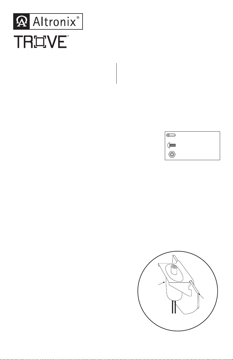
3. Mount UL Listed tamper switch (Included)
(Ademco model 112 or equivalent) in desired location,
opposite hinge. Slide the tamper switch bracket onto
the edge of the enclosure approximately 2” from the
right side (Fig. 1, pg. 1). Connect tamper switch
wiring to the Access Control Panel input or the
appropriate UL Listed reporting device.
To activate alarm signal open the door of the enclosure.
4. Mount Altronix/AMAG boards to backplane,
refer to pages 2, 3, 4.
Fig. 1
Page 2
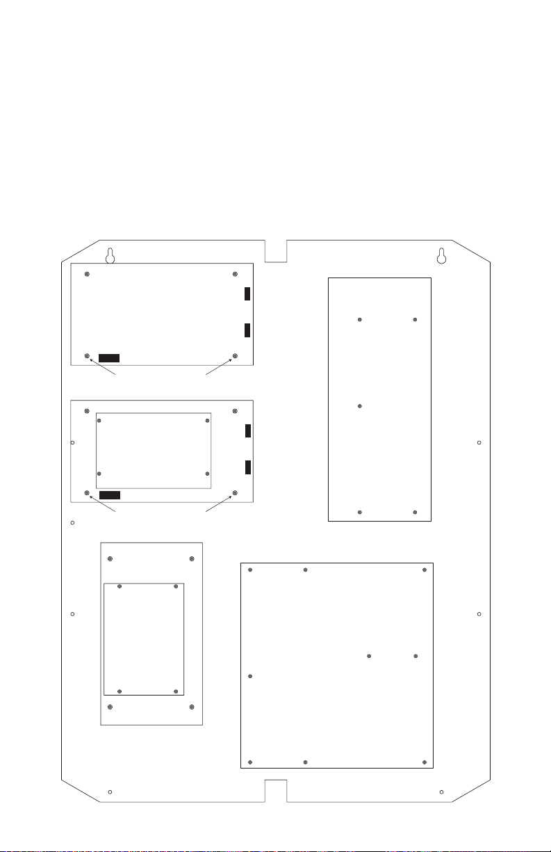
TAM2: Configuration of Altronix Power Supply and/or
Altronix
Power Supply
Altronix
Power Supply or
Sub-Assembly
Metal Standoff Placement
Metal Standoff Placement
Altronix
Sub-
Assembly
Sub-Assembly Boards and AMAG Boards
AMAG M2150 2DC and M2150 2DBC
1. Fasten standoffs (provided) to pems that match the hole pattern for Altronix Power Supply/Chargers
or Altronix Sub-Assembly boards (Fig. 2, pg. 2).
Fasten metal standoffs in the correct locations to provide proper grounding, see below (Fig. 2, pg. 2).
2. Mount boards to standoffs utilizing 5/16” pan head screws (provided) (Fig. 2, pg. 2).
3. Align the AMAG boards on the backplane to match the boards’ mounting holes with pems provided.
4. Fasten standoffs (provided) to pems that match the hole pattern for AMAG M2150 2DC and
M2150 2DBC boards.
5. Mount AMAG boards to standoffs utilizing 5/16” pan head screws (provided) (Fig. 2, pg. 2).
Note: AMAG M2150 2DC boards have specific markings.
Please orient boards in the appropriate position according to the Fig. 2 below.
6. Fasten backplane to Trove2 enclosure utilizing lock nuts (provided).
Fig. 2
Altronix
Power Supply
Metal Standoff Placement
AMAG
M2150 2DC
Altronix
Power Supply or
Sub-Assembly
READER 1
Metal Standoff Placement
Altronix
Sub-
Assembly
AMAG
M2150 2DBC
- 2 - Trove2AM2/TAM2 - Altronix/AMAG
Page 3
Altronix
Power Supply
Altronix
Power Supply or
Sub-Assembly
Metal Standoff Placement
Metal Standoff Placement
Altronix
Sub-
Assembly
TAM2: Configuration of Altronix Power Supply and/or
Sub-Assembly Boards and AMAG Boards
AMAG M2150 4DC, M2150 4DBC, and M2150 8DBC
1. Fasten standoffs (provided) to pems that match the hole pattern for Altronix Power Supply/Chargers
or Altronix Sub-Assembly boards (Fig. 3, pg. 3).
Fasten metal standoffs in the correct locations to provide proper grounding, see below (Fig. 3, pg. 3).
2. Mount boards to standoffs utilizing 5/16” pan head screws (provided) (Fig. 3, pg. 3).
3. Align the AMAG boards on the backplane to match the boards’ mounting holes with pems provided.
4. Fasten standoffs (provided) to pems that match the hole pattern for AMAG M2150 4DC,
M2150 4DBC, and M2150 8DBC boards.
5. Mount AMAG boards to standoffs utilizing 5/16” pan head screws (provided) (Fig. 3, pg. 3).
Note: AMAG M2150 4DBC and M2150 8DBC boards have specific markings.
Please orient boards in the appropriate position according to the Fig. 3 below.
6. Fasten backplane to Trove2 enclosure utilizing lock nuts (provided).
Fig. 3
Altronix
Power Supply
Metal Standoff Placement
Altronix
Power Supply or
Sub-Assembly
Metal Standoff Placement
AMAG
M2150 4DC
READER 1
Altronix
Sub-
Assembly
AMAG
M2150 4DBC,
M2150 8DBC
COM C
RS232
Trove2AM2/TAM2 - Altronix/AMAG - 3 -
Page 4

TAM2: Configuration of Altronix Power Supply and/or
Sub-Assembly Boards and AMAG Boards
AMAG M2150 AC24/4, M2150 4DBC, and M2150 8DBC
1. Fasten standoffs (provided) to pems that match the hole pattern for Altronix Power Supply/Chargers
or Altronix Sub-Assembly boards (Fig. 4, pg. 4).
Fasten metal standoffs in the correct locations to provide proper grounding, see below (Fig. 4, pg. 4).
2. Mount boards to standoffs utilizing 5/16” pan head screws (provided) (Fig. 4, pg. 4).
3. Align the AMAG boards on the backplane to match the boards’ mounting holes with pems provided.
4. Fasten standoffs (provided) to pems that match the hole pattern for AMAG M2150 AC24/4,
M2150 4DBC, and M2150 8DBC boards.
5. Mount AMAG boards to standoffs utilizing 5/16” pan head screws (provided) (Fig. 4, pg. 4).
Note: AMAG M2150 4DBC and M2150 8DBC boards have specific markings.
Please orient boards in the appropriate position according to the Fig. 4 below.
6. Fasten backplane to Trove2 enclosure utilizing lock nuts (provided).
Fig. 4
Altronix
Power Supply
AMAG
Metal Standoff Placement
M2150 AC24/4
Altronix
Power Supply or
Sub-Assembly
Metal Standoff Placement
READER 1
Altronix
Sub-
Assembly
AMAG
M2150 4DBC,
M2150 8DBC
COM C
RS232
- 4 - Trove2AM2/TAM2 - Altronix/AMAG
Page 5

Notes:
Trove2AM2/TAM2 - Altronix/AMAG - 5 -
Page 6

Notes:
- 6 - Trove2AM2/TAM2 - Altronix/AMAG
Page 7
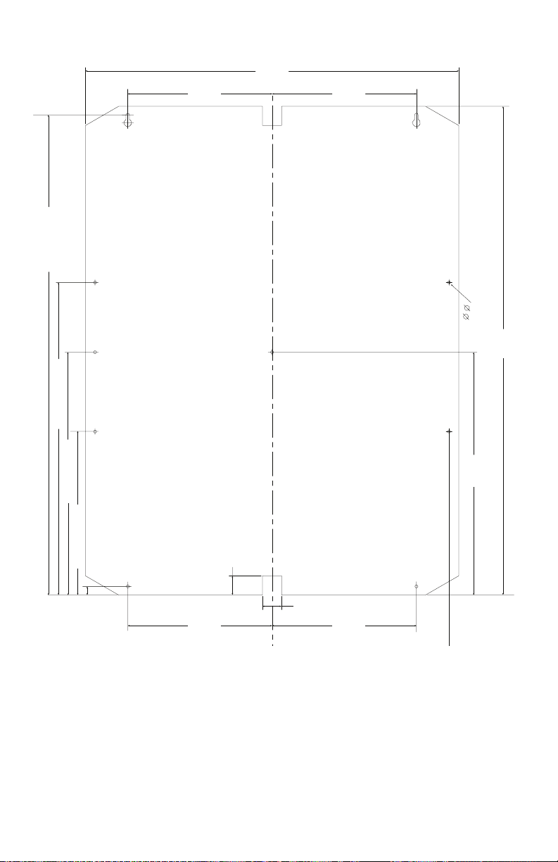
Fig. 5
24.95” (633.73mm)
16.245” (412.62mm)
TAM2 Dimensions
19.4”
7.5”
(190.5mm)
(492.76mm)
7.5”
(190.5mm)
0.156”
( 3.96mm)
(645.16mm)
25.4”
12.62”
(320.55mm)
12.62” (320.55mm)
1.0”
7.5”
(190.5mm)
(25.4mm)
1.0”
(25.4mm)
7.5”
(190.5mm)
8.495” (215.77mm)
0.45”
(11.43mm)
Trove2AM2/TAM2 - Altronix/AMAG - 7 -
Page 8
6.25”
(
)
(
)
(
)
(
)
(
)
(158.75mm)
1.25”
(31.75mm)
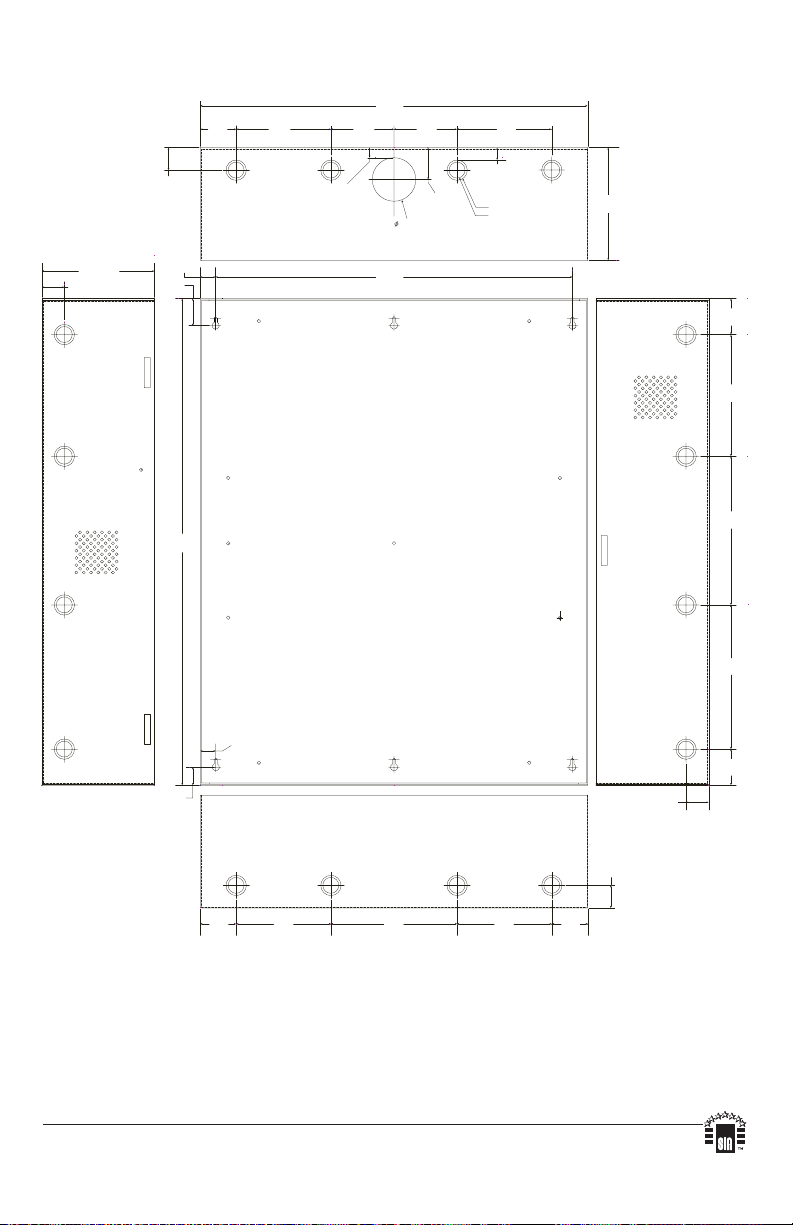
Trove2AM2 Enclosure Dimensions (H x W x D):
27.25” x 21.75” x 6.5” (692.15mm x 552.45mm x 165.1mm)
21.50”
(88.9mm)
0.5625”
(14.29mm)
3.50”
(546.1mm)
2.415”
(61.34mm)
19.80”
(502.92mm)
3.50”
(88.9mm)
1.77”
(44.96mm)
5.25”
(133.35mm)
0.685”
(17.399mm)
Knockouts
1.125” (28.32mm)
0.885” (22.479mm)
(31.75mm)
G
1.25”
0.85”
(21.59mm)
1.5”
(38.1mm)
27.00”
(685.8mm)
2.00”
(50.8mm)
5.25”
(133.35mm)
6.25”
(158.75mm)
2.00”
(50.8mm)
6.75”
(171.45mm)
8.25”
(209.54mm)
8.00”
(203.2mm)
0.85”
(21.59mm)
2.00”
(50.8mm)
1.00”
(25.4mm)
2.00”
50.8mm
5.25”
133.35mm
7.00”
177.79mm
5.25”
133.35mm
2.00”
50.8mm
1.25”
(31.75mm)
1.25”
(31.75mm)
Altronix is not responsible for any typographical errors.
140 58th Street, Brooklyn, New York 11220 USA, 718-567-8181, fax: 718-567-9056
website: www.altronix.com, e-mail: info@altronix.com. Made in U.S.A.
IITrove2AM2 - Rev. 06222016 F22P
- 8 - Trove2AM2/TAM2 - Altronix/AMAG
MEMBER
 Loading...