

Page 1

Access & Power Integration
T3KAK33F16
16 Door Kit with Fused Outputs
Fully assembled kit includes:
- Trove3 enclosure with TKA3 Altronix/Keyscan backplane
- (2) eFlow6NB - Power Supply/Chargers
- (2) ACM8 - Fused Access Power Controllers
- (1) PD4UL - Fused Power Distribution Board
- (1) T16175 Transformer (packed separately)
All components of this Trove kit are UL Listed sub-assemblies.
Please refer to the included corresponding Sub-Assembly Installation Guides for further information.
Installation Guide
All registered trademarks are property of their respective owners. More than just power.™
Rev. T3KAK33F16_112119
Installing Company: _____________________ Service Rep. Name: __________________________________________
Address: ________________________________________________________ Phone #: _________________________
Page 2
Overview:
Tamper Switch
(provided)
To Access Control Panel or
UL Listed Reporting Device
Edge of
Enclosure
Enclosure
TKA3
Lock Nut
Mounting
Hole
Mounting Bracket
Terminals
T16175
Altronix T3KAK33F16 Trove Keyscan kit is pre-assembled and consist of Trove3KA3 enclosure/backplane with factory installed Altronix
power supply/chargers, transformer, and sub-assemblies. This kit also accommodates various combinations of Keyscan boards for up to
sixteen (16) doors in a single enclosure.
Configuration Chart:
Altronix
Model
Number
T3KAK33F16
120VAC
60Hz
Input
Current
(A)
7.0
Power
Supply
Boards
Input
Fuse
Rating
5A/
250V
Power
Supply
Boards
Battery
Fuse
Rating
10A/
32V
Nominal DC
Output Voltage
[DC] [Aux]
24VDC
Output
Range (V)
20.19-26.4 20.19-26.4 24VDC @ 5.8A 16 2.5
24VDC
Output
Range (V)
Maximum Supply
Current for Main
and Aux. Outputs
on each Power
Supply board
and each ACM8
Access Power
Controller’s outputs
Fail-Safe/
Fail-Secure
or Dry Form
“C” Outputs
Current Per
ACM8
Output (A)
ACM8
Board
Input
Fuse
Rating
10A/
250V
ACM8
Board
Output
Fuse
Rating
3.5A/
250V
PD4UL
Board
Output
Fuse
Rating
3.5A/
250V
Installation Instructions:
Wiring methods shall be in accordance with the National Electrical Code/NFPA 70/ANSI and with all local codes and authorities having
jurisdiction. Product is intended for indoor use only.
1. Remove backplane from enclosure. Do not discard hardware.
2. Mark and predrill holes in the wall to line up with the top three keyholes in the enclosure. Install three upper fasteners and screws
in the wall with the screw heads protruding. Place the enclosure’s upper keyholes over the three
upper screws, level and secure. Mark the position of the lower three holes. Remove the enclosure.
Drill the lower holes and install the three fasteners. Place the enclosure’s upper keyholes over the three
upper screws. Install the three lower screws and make sure to tighten all screws.
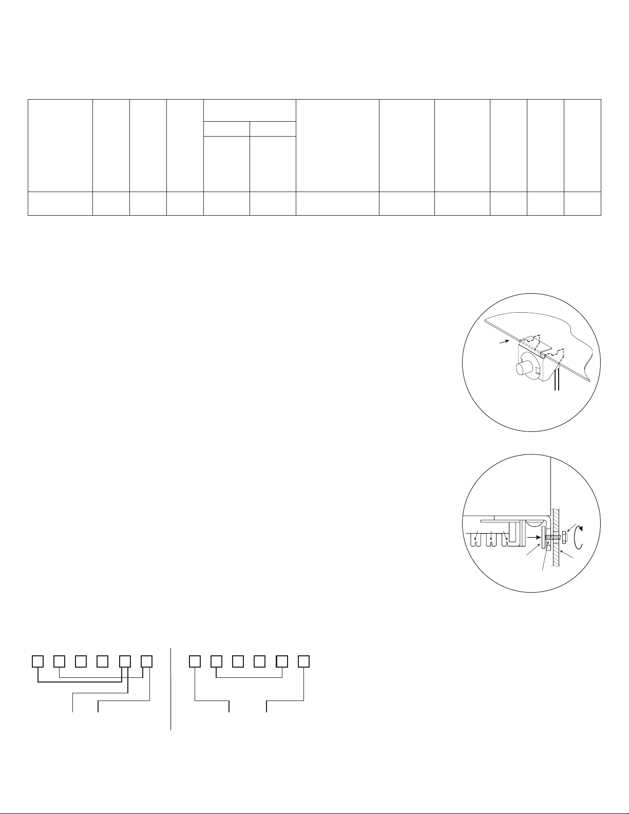
3. Mount included UL Listed tamper switch (Altronix Model TS112 or equivalent) in desired
location, opposite hinge. Slide the tamper switch bracket onto the edge of the enclosure
approximately 2” from the right side (Fig. 1, pg. 2). Connect tamper switch wiring to the
Access Control Panel input or the appropriate UL Listed reporting device.
To activate alarm signal open the door of the enclosure.
4. Mounting Included T16175 Transformer:
To prevent damage, T16175 is packed separately and needs to be installed by the user.
It is to be mounted on the left of the backplane, next to PD4UL power distribution board.
Please follow the steps below:
a. Orient T16175 so the terminals are facing down (Fig. 4, 4a, pg. 3).
b. Put T16175’s upper mounting holes over two mounting pems on backplane and secure with
two (2) lock nuts (Fig. 4, 4a, pg. 3).
c. Use included mounting bracket to secure T16175’s lower mounting holes. Align pems on the
bracket with T16175’s lower mounting holes and corresponding holes in the backplane.
Push the bracket’s pems through the holes and secure from the back side of the backplane
with two (2) lock nuts (Fig. 2, pg. 2).
d. Connect AC power 115VAC, 50/60Hz to primary leads (black and white) from
terminal numbers 1 and 2 (Fig. 3, pg. 2).
e. Measure output voltage across the secondary leads (yellow and blue) from
terminal numbers 7 and 12 (Fig. 3, pg. 2) before connecting devices.
This helps avoiding potential damage.
f. Connect PD4UL (factory mounted) to the secondary leads (yellow and blue) from
terminal numbers 7 and 12 (Fig. 3, pg. 2).
5. Mount Keyscan boards to backplane, refer to page 3.
6. Refer to the eFlow Power Supply/Charger Installation Guide (for eFlow6NB), ACM8/CB Installation Guide for ACM8,
and T16175 Installation Guide for T16175 for further installation instructions.
Fig. 1
Fig. 2
Fig. 3 - T16175 Wiring Configuration
4 356 2 1 10 91112 8 7
- 2 - T3KAK33F16
16VAC (Secondary) Output115VAC (Primary) Input
Page 3

1 2 3 4
ON
1 2 3 4
ON
1 2 3 4
ON
1 2 3 4
ON
T3KAK33F16: Configuration of Keyscan Boards
1. Mount appropriate Keyscan boards into the correct positions (Fig. 4, pg. 3) by postioning spacers over appropriate holes in the
backplane and depressing down on board to secure spacer to the backplane (Fig. 4b, pg. 3).
2. Fasten backplane to Trove2 enclosure utilizing pan head screws (provided).
Fig. 4
OFF - 24V
ON
ON - 12V
Altronix
Fig. 4a
Lock Nuts
L G N
L G N
eFlow6NB
NC C NO NC
AC FAIL BAT FAIL
Altronix
eFlow6NB
NC C NO NC
AC FAIL BAT FAIL
AC DCAC1
EOLNOGND
TRIGGER
C NO
C NO
+AUX-
SUPERVISED RESET
OFF - 24V
ON
ON - 12V
AC DCAC1
EOL NO GND
TRIGGER
+AUX-
SUPERVISED RESET
F1 F2 F3 F4
1P 1N 2P 2N 3P 3N 4P 4N
- BAT +- DC +
Keyscan
CA250B,
CA4500B
CA8500B
- BAT +- DC +
Keyscan
OCB8
Keyscan
OCB8
Altronix
T16175
Terminals
Bracket
Altronix
T16175
(packed separately)
1 2 3 4
F1 F2 F3 F4 F5 F6 F7 F8
NC C NO COM NC C NO COM NC C NO COM NC C NO COM NC C NO COM NC C NO COM NC C NO COM NC C NO COM
OUTPUT 1 OUTPUT 2 OUTPUT 3 OUTPUT 4 OUTPUT 5 OUTPUT 6 OUTPUT 7 OUTPUT 8
1 2 3 4
F1 F2 F3 F4 F5 F6 F7 F8
NC C NO COM NC C NO COM NC C NO COM NC C NO COM NC C NO COM NC C NO COM NC C NO COM NC C NO COM
OUTPUT 1 OUTPUT 2 OUTPUT 3 OUTPUT 4 OUTPUT 5 OUTPUT 6 OUTPUT 7 OUTPUT 8
IN GND IN GND IN GND IN GNDIN GND IN GND IN GND IN GND
5 6 7 8
IN GND IN GND IN GND IN GNDIN GND IN GND IN GND IN GND
5 6 7 8
P N
Altronix PD4UL
TRIGGER
INPUT
TRIGGER
INPUT
FACP
ON
1 2 3 4
Altronix
ACM8
FACP
ON
1 2 3 4
Altronix
ACM8
Keyscan
DPS15
TRG
+INP- T + RET-
ON
FACP INTERFACE
1 2 3 4
NO C NC
MAIN
10A 250V
- + - +
Power Control
TRG
+INP- T + RET-
ON
FACP INTERFACE
1 2 3 4
NO C NC
MAIN
10A 250V
- + - +
Power Control
Keyscan
DPS15
Locknut
Keyscan
CA250B,
CA4500B
CA8500B
Locknut
Keyscan
CIM
Keyscan
OCB8
Keyscan
OCB8
Keyscan
CIM
Plastic Spacer
pre-mounted into
Keyscan modules
Insert into
TKA2 or
TKA3 backplane
T3KAK33F16 - 3 -
Fig. 4b
Page 4

Enclosure Dimensions (H x W x D approximate):
(50.8mm)
1.25” (31.8mm)
2.00” (50.8mm) 7.12” (222.3mm)
9.5” (241.3mm) 9.5” (241.3mm)
36.12” x 30.125” x 7.06” (917.5mm x 768.1mm x 179.3mm)
2.00” (50.8mm)10.75” (273.1mm)10.75” (273.1mm) 10.62” (269.8mm)
1.25” (31.8mm)
1.25” (31.8mm)
1.07”
(27.2mm)
G
G
1.10” (27.9mm)
33.63” (854.2mm)
30.12” (768.1mm)
14.01” (355.9mm)
1.78” (45.2mm)
14.01” (355.9mm)
1.55” (39.4mm)
2” (50.8mm)
10.75” (273.1mm)10.75” (273.1mm) 10.62” (269.8mm)
36.12” (917.5mm)
7.06” (179.3mm)
1.25” (31.8mm)
2”
8.75” (222.3mm)
8.62” (219mm)
8.75” (222.3mm)
Altronix is not responsible for any typographical errors.
140 58th Street, Brooklyn, New York 11220 USA | phone: 718-567-8181 | fax: 718-567-9056
web site: www.altronix.com | e-mail: info@altronix.com | Lifetime Warranty | Made in U.S.A.
IIT3KAK33F16 K21S
- 4 - T3KAK33F16
MEMBER
 Loading...