

Page 1

Access & Power Integration
T1CVK3F4
4 Door Kit with Fused Outputs
Fully assembled kit includes:
- Trove1 enclosure with TC1 Altronix/CDVI backplane
- One (1) eFlow6NB - Power Supply/Charger
- One (1) ACM4 - Fused Access Power Controller
T2CVK7F10
10 Door Kit with Fused Outputs
Fully assembled kit includes:
- Trove2 enclosure with TCV2 Altronix/CDVI backplane
- One (1) eFlow104NB - Power Supply/Charger
- One (1) ACM8 - Fused Access Control Module
- One (1) ACM4 - Fused Access Control Module
- One (1) PD8UL - Fused Power Distribution Module
T2CVK33F10
10 Door Kit with PTC Outputs
Fully assembled kit includes:
- Trove2 enclosure with TCV2 Altronix/CDVI backplane
- Two (2) eFlow6NB - Power Supply/Chargers
- Two (2) MOM5 - PTC Power Distribution Modules with
Fire Alarm Interface
T2CVK33F10Q
10 Door Kit with PTC Outputs
Fully assembled kit includes:
- Trove2 enclosure with TCV2 Altronix/CDVI backplane
- One (1) LINQ2 - Network Communication Module
- Two (2) eFlow6NB - Power Supply/Chargers
- Two (2) MOM5 - PTC Power Distribution Modules with
Fire Alarm Interface
T3CVK77F20
20 Door Kit with Fused Outputs
Fully assembled kit includes:
- Trove3 enclosure with TCV3 Altronix/CDVI backplane
- Two (2) eFlow104NB - Power Supply/Chargers
- Two (2) ACM8 - Fused Access Control Modules
- One (1) ACM4 - Fused Access Control Module
- One (1) PD8UL - Fused Power Distribution Module
- One (1) RSB2 - Rocker Switch Bracket with
Two (2) Rocker Switches (Not evaluated by UL)
All components of these Trove kits are UL Listed sub-assemblies.
Please refer to the included corresponding Sub-Assembly Installation Guides for further information.
Installation Guide
All registered trademarks are property of their respective owners. More than just power.™
Rev. TCVK_042619
Installing Company: _____________________ Service Rep. Name: __________________________________________
Address: ________________________________________________________ Phone #: _________________________
Page 2

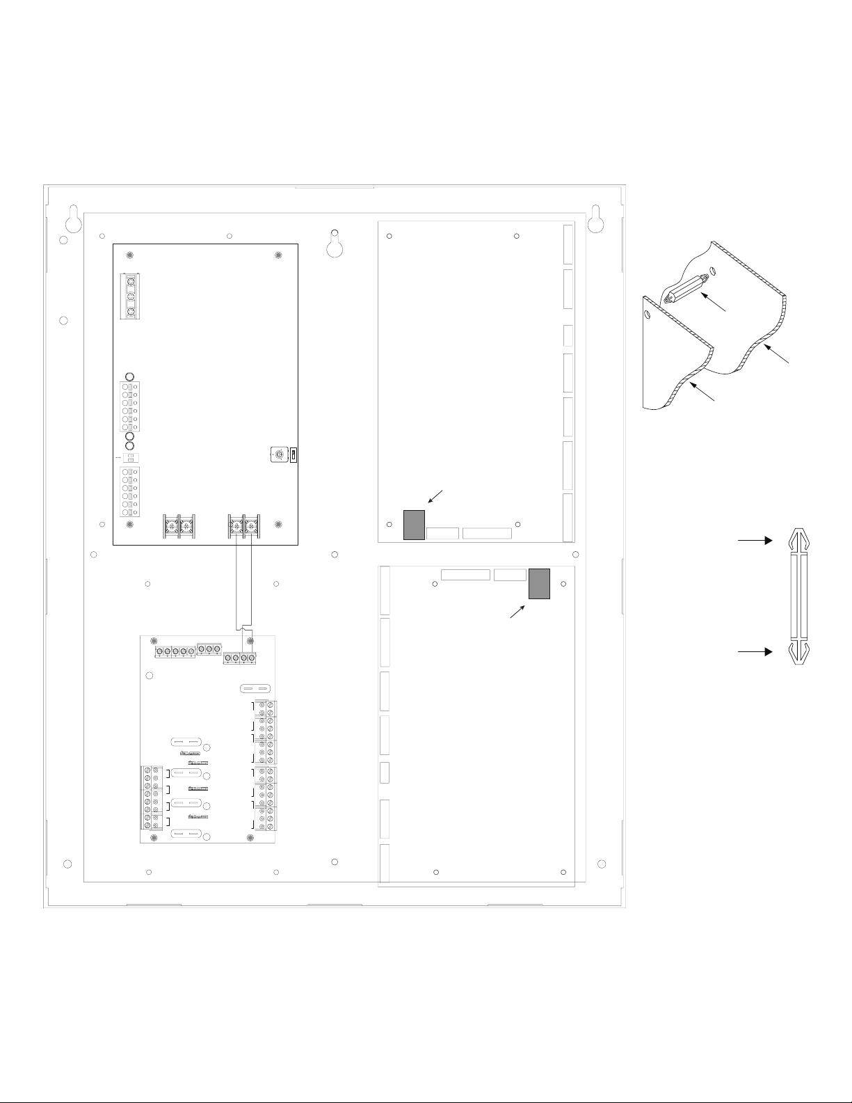
Overview:
Tamper Switch
(provided)
To Access Control Panel or
UL Listed Reporting Device
Edge of
Enclosure
Enclosure
Altronix Trove CDVI kits are pre-assembled and consist of Trove enclosures/backplanes with factory installed Altronix power supply/
chargers and sub-assemblies. These kits also accommodate various combinations of CDVI Atrium A22K/A22NB/ADH10 boards for up
to twenty (20) doors in a single enclosure.
Configuration Chart:
Nominal DC
Output Voltage
Power Supply
[DC] [Aux]
Output
Range
(VDC)
20.17-
20.17-
20.17-
20.17-
20.17-
26.4
26.4
26.4
26.4
26.4
9.7-
13.2
Output
Range
(VDC)
20.28-
26.4
20.28-
26.4
20.28-
26.4
20.28-
26.4
20.28-
26.4
10.03-
13.2
Fail-Safe/Fail-Secure or
Dry Form “C” Outputs
Additional Fuse or PTC
Protected Outputs
ACM4/ACM8 Board
Input Fuse Rating
ACM4 Board Output
Fuse Rating
ACM8 Board Output
Fuse Rating
10A/
10A/
10A/
3A/
32V
2.5A/
250V
3A/
32V
4 –
12 8
– 10 – – – –
– 10 – – – –
20 8
250V
250V
250V
– – –
2.5A/
250V
2.5A/
250V
PD8UL Board
Output Fuse Rating
MOM5 Output
3.5A/
250V
3.5A/
250V
–
2A/
250V
2A/
250V
–
Altronix
Model Number
T1CVK3F4
T2CVK7F10
T2CVK33F10
T2CVK33F10Q
T3CVK77F20
Networkable
– 5A/250V
– 6.3A/250V
– 5A/250V
P
– 6.3A/ 250V
Power Supply Board
Input Fuse Rating
5A/250V
Maximum Supply
Current for Main and
Aux. Outputs on
Power Supply board,
distribution module
or ACM4/ACM8
Power Supply Board
Battery Fuse Rating
15A/
32V
15A/
32V
15A/
32V
15A/
32V
15A/
32V
Controllers’ outputs
120VAC 60Hz
Input Current (A)
3.5 24VDC @ 5.7A
4.5 24VDC @ 9.4A
7.0
7.0
9.0
MOM5 power
Access Power
24VDC @ 5.9A
+
24VDC @ 5.9A
24VDC @ 5.9A
+
24VDC @ 5.9A
24VDC @ 9.4A
+
24VDC @ 9.7A
PTC Rating
Installation Instructions:
Wiring methods shall be in accordance with the National Electrical Code/NFPA 70/ANSI, and with all local codes and authorities having
jurisdiction. Product is intended for indoor use only.
1. Remove backplane from enclosure. Do not discard hardware.
If your application requires a raised backplane, re-mount it using metal spacers and screws (provided).
2. Mark and predrill holes in the wall to line up with the top three keyholes in the enclosure. Install two/three upper fasteners and screws
in the wall with the screw heads protruding. Place the enclosure’s upper keyholes over the two/three upper screws; level and secure.
Mark the position of the lower two/three holes. Remove the enclosure. Drill the lower holes and install the fasteners. Place the
enclosure’s upper keyholes over the upper screws. Install the lower screws and make sure to tighten all screws.
3. Mount included UL Listed tamper switch(es) (Altronix Model TS112 or equivalent) in desired location, opposite hinge. Slide the
tamper switch bracket onto the edge of the enclosure approximately 2” from the right side (Fig. 1, pg. 2). Connect tamper switch wiring
to the Access Control Panel input or the appropriate UL Listed reporting device. To activate alarm signal open the door of the enclosure.
4. Mount CDVI A22K/A22NB/ADH10 boards to backplane, refer to pages 3-4.
5. Refer to the eFlow Power Supply/Charger Installation Guide (eFlow6NB, eFlow102NB,
eFlow104NB) and corresponding Sub-Assembly Installation Guide (LINQ2, ACM4, ACM8,
PD8UL, MOM5) for further installation instructions.
Fig. 1
- 2 - Trove CDVI Kits
Page 3
T1CVK3F4: Configuration of CDVI A22K/A22NB/ADH10 Boards
1. Fasten spacers (supplied with A22K/A22NB/ADH10) to CDVI A22K/A22NB/ADH10 board (Fig. 2b, pg. 3).
2. Mount CDVI A22K/A22NB/ADH10 boards into the correct positions (Fig. 2, pg. 3) by postioning spacers over appropriate holes
on the backplane and depressing down on board to secure spacer to the backplane (Fig. 2a, 2b, pg. 3).
Note: CDVI A22K/A22NB/ADH10 boards have one (1) RJ45 jack each.
Please make sure that they are mounted correctly, as shown in Fig. 2 below.
3. Fasten backplane to Trove2 enclosure utilizing pan head screws (provided).
Fig. 2
Fig. 2a
L G N
Spacer
NC C NO NC
AC FAIL BAT FAIL
C NO
AC DCAC1
TRIGGER
SUPERVISED RESET
EOL NO GND
+AUX-
Altronix
eFlow6NB
- BAT +- DC +
INTERFACE
+ INP --- T + RET ---
TRG
Altronix
ACM4
SW4
INPUT
TRIGGER
4
IN GND
3
IN GND
2
IN GND
SW1 SW2 SW3
1
IN GND
FACP
LED1 LED2 LED3 LED4
NO C NC
CDVI
Backplane
ON - 12V
A22K/A22NB/ADH10
CDVI - A22K/A22NB/ADH10
Access Controller
ON
OFF - 24V
RJ45 Jack
Fig. 2b
Plastic Spacer
pre-mounted into
CDVI Atrium modules
RJ45 Jack
Control
Power
--- +
--- +
Insert into
TC1 backplane
MAIN
A22K/A22NB/ADH10
OUTPUT 4
NC C NO COM
OUTPUT 3
NC C NO COM
OUTPUT 2
NC C NO COM
OUTPUT 1
NC C NO COM
CDVI
Trove CDVI Kits
- 3 -
Page 4
T2CVK7F10: Configuration of CDVI A22K/A22NB/ADH10 Boards
1 2 3 4
ON
1 2 3 4
ON
1. Fasten spacers (supplied with A22K/A22NB/ADH10) to CDVI A22K/A22NB/ADH10 board (Fig. 3b, pg. 4).
2. Mount CDVI A22K/A22NB/ADH10 boards into the correct positions (Fig. 3, pg. 4) by postioning spacers over appropriate holes
on the backplane and depressing down on board to secure spacer to the backplane (Fig. 3a, 3b, pg. 4).
Note: CDVI A22K/A22NB/ADH10 boards have one (1) RJ45 jack each.
Please make sure that they are mounted correctly, as shown in Fig. 3 below.
3. Fasten backplane to Trove2 enclosure utilizing pan head screws (provided).
Fig. 3
Fig. 3a
Altronix
eFlow104NB
TRIGGER
5 6 7 8
INPUT
IN GND IN GND IN GND IN GNDIN GND IN GND IN GND IN GND
1 2 3 4
F1 F2 F3 F4 F5 F6 F7 F8
FACP
ON
Altronix ACM8
NC C NO COM NC C NO COM NC C NO COM NC C NO COM NC C NO COM NC C NO COM NC C NO COM NC C NO COM
OUTPUT 1 OUTPUT 2 OUTPUT 3 OUTPUT 4 OUTPUT 5 OUTPUT 6 OUTPUT 7 OUTPUT 8
FACP
INTERFACE
NO C NC
+ INP --- T + RET ---
Control
TRG
Altronix
ACM4
SW4
INPUT
TRIGGER
4
IN GND
3
IN GND
2
IN GND
SW1 SW2 SW3
1
IN GND
Power
--- +
--- +
MAIN
OUTPUT 4
NC C NO COM
OUTPUT 3
NC C NO COM
OUTPUT 2
NC C NO COM
OUTPUT 1
NC C NO COM
LED1 LED2 LED3 LED4
Altronix
PD8UL
1 2 3 4 5 6 7 8
RJ45 Jack
--- BAT + --- DC +
CDVI - A22K/A22NB/ADH10
Spacer
Backplane
CDVI - A22K/A22NB/ADH10
TRG
+INP- T + RET-
ON
1 2 3 4
FACP INTERFACE
1 2 3 4
NO C NC
MAIN
10A 250V
RJ45 Jack
CDVI - A22K/A22NB/ADH10
Access Controller
Fig. 3b
- + - +
Power Control
Plastic Spacer
pre-mounted into
CDVI Atrium modules
LED
INPUT
D1
R1
P N
RJ45 Jack
CDVI - A22K/A22NB/ADH10
Insert into
TCV2 backplane
FUSED POWER OUTPUTS
COMMON POWER OUTPUTS
N
P
RJ45 Jack
CDVI - A22K/A22NB/ADH10
RJ45 Jack
CDVI - A22K/A22NB/ADH10
- 4 - Trove CDVI Kits
Page 5

T2CVK33F10 and T2CVK33F10Q: Configuration of CDVI A22K/A22NB/ADH10 Boards
1. Fasten spacers (supplied with A22K/A22NB/ADH10) to CDVI A22K/A22NB/ADH10 board (Fig. 4b, pg. 5).
2. Mount CDVI A22K/A22NB/ADH10 boards into the correct positions (Fig. 4, pg. 5) by postioning spacers over appropriate holes
on the backplane and depressing down on board to secure spacer to the backplane (Fig. 4a, 4b, pg. 5).
Note: CDVI A22K/A22NB/ADH10 boards have one (1) RJ45 jack each.
Please make sure that they are mounted correctly, as shown in Fig. 4 below.
3. Fasten backplane to Trove2 enclosure utilizing pan head screws (provided).
Fig. 4
LINQ2 Module (T2CVK33F10Q)
- DC INPUT +
L G N
L G N
- INPUT +
Altronix
MOM5
Altronix
eFlow6NB
NC C NO NC
AC FAIL BAT FAIL
Altronix
eFlow6NB
NC C NO NC
AC FAIL BAT FAIL
TRIGGER
POWER
ON LED
NC C NO NC C NO
DRY OUTPUT POWER FAIL
LED
TRIGGER
C NO
C NO
ON
AC DCAC1
ON
AC DCAC1
- DC INPUT +
OFF - 24V
ON - 12V
EOL NO GND
TRIGGER
+AUX-
SUPERVISED RESET
OFF - 24V
ON - 12V
EOL NO GND
TRIGGER
+AUX-
SUPERVISED RESET
- INPUT +
Altronix
MOM5
Fig. 4a
RJ45 Jack
- BAT +- DC +
CDVI - A22K/A22NB/ADH10
RJ45 Jack
- BAT +- DC +
CDVI - A22K/A22NB/ADH10
Fig. 4b
Spacer
Backplane
CDVI - A22K/A22NB/ADH10
Access Controller
Plastic Spacer
pre-mounted into
TRIGGER
POWER
ON LED
NC C NO NC C NO
DRY OUTPUT POWER FAIL
TRIGGER
LED
RJ45 Jack
CDVI - A22K/A22NB/ADH10
CDVI Atrium modules
Insert into
TCV2 backplane
Trove CDVI Kits
POS (+) DC OUTPUT (ALARM)
1 2 3 4 5
6 7 8 9 10
NEG1 NEG2 NEG3 NEG4 NEG5
POS (+) DC OUTPUT (STANDBY)
NEG1 NEG2 NEG3 NEG4 NEG5
RJ45 Jack
CDVI - A22K/A22NB/ADH10
POS (+) DC OUTPUT (ALARM)
1 2 3 4 5
6 7 8 9 10
POS (+) DC OUTPUT (STANDBY)
RJ45 Jack
CDVI - A22K/A22NB/ADH10
- 5 -
Page 6

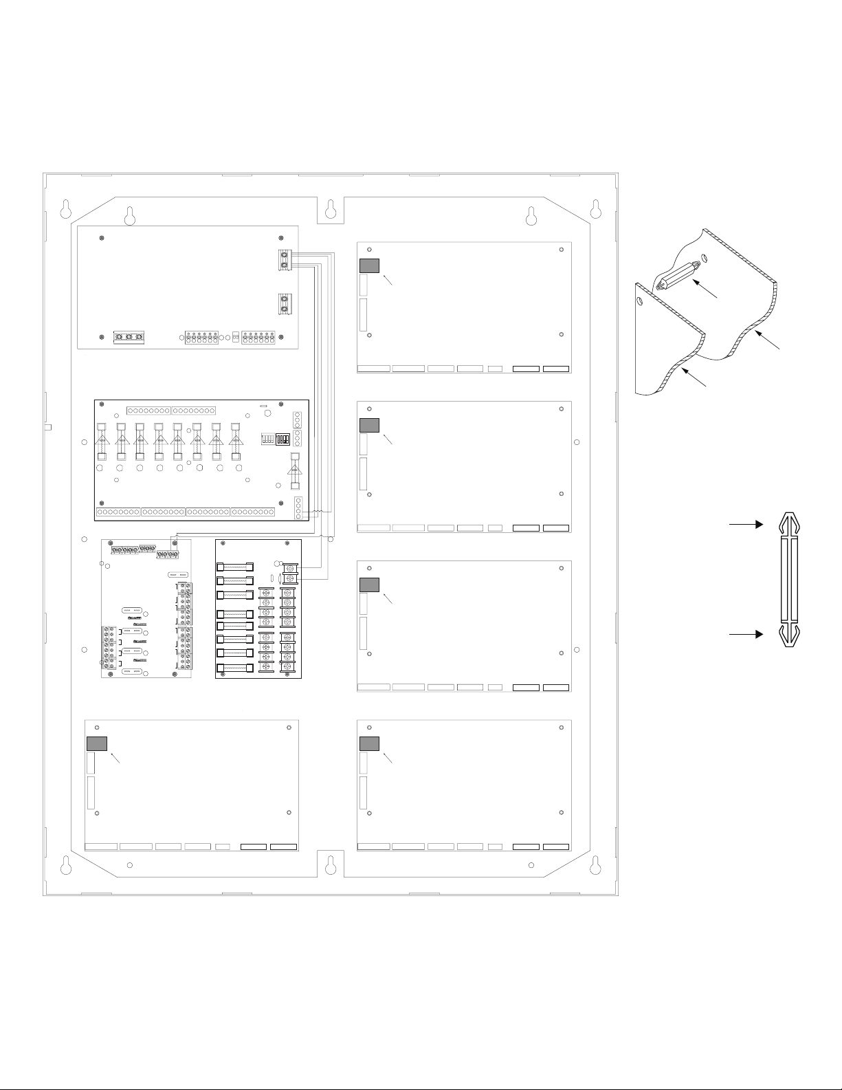
T3CVK77F20: Configuration of CDVI A22K/A22NB/ADH10 Boards
1 2 3 4
ON
1 2 3 4
ON
1 2 3 4
ON
1 2 3 4
ON
1. Fasten spacers (supplied with A22K/A22NB/ADH10) to CDVI A22K/A22NB/ADH10 board (Fig. 5b, pg. 6).
2. Mount CDVI A22K/A22NB/ADH10 boards into the correct positions (Fig. 5, pg. 6) by postioning spacers over appropriate holes
on the backplane and depressing down on board to secure spacer to the backplane (Fig. 5a, 5b, pg. 6).
Note: CDVI A22K/A22NB/ADH10 boards have one (1) RJ45 jack each.
Please make sure that they are mounted correctly, as shown in Fig. 5 below.
3. Fasten backplane to Trove3 enclosure utilizing pan head screws (provided).
Fig. 3
Rocker Switch
Altronix
eFlow104NB
L G N
Altronix
eFlow104NB
RSB2 Bracket
L G N
IN GND IN GND IN GND IN GNDIN GND IN GND IN GND IN GND
5 6 7 8
1 2 3 4
F1 F2 F3 F4 F5 F6 F7 F8
NC C NO COM NC C NO COM NC C NO COM NC C NO COM NC C NO COM NC C NO COM NC C NO COM NC C NO COM
OUTPUT 1 OUTPUT 2 OUTPUT 3 OUTPUT 4 OUTPUT 5 OUTPUT 6 OUTPUT 7 OUTPUT 8
IN GND IN GND IN GND IN GNDIN GND IN GND IN GND IN GND
5 6 7 8
1 2 3 4
F1 F2 F3 F4 F5 F6 F7 F8
NC C NO COM NC C NO COM NC C NO COM NC C NO COM NC C NO COM NC C NO COM NC C NO COM NC C NO COM
OUTPUT 1 OUTPUT 2 OUTPUT 3 OUTPUT 4 OUTPUT 5 OUTPUT 6 OUTPUT 7 OUTPUT 8
– DC +– BAT +
RJ45 Jack
CDVI - A22K/A22NB/ADH10
– DC +– BAT +
RJ45 Jack
CDVI - A22K/A22NB/ADH10
FACP
TRIGGER
TRG
INPUT
ON
1 2 3 4
Altronix
ACM8
+INP- T + RET-
ON
FACP INTERFACE
1 2 3 4
NO C NC
MAIN
10A 250V
RJ45 Jack
CDVI - A22K/A22NB/ADH10
- + - +
Power Control
FACP
TRIGGER
TRG
INPUT
ON
1 2 3 4
Altronix
ACM8
+INP- T + RET-
ON
FACP INTERFACE
1 2 3 4
NO C NC
MAIN
10A 250V
RJ45 Jack
CDVI - A22K/A22NB/ADH10
- + - +
Power Control
RJ45 Jack
CDVI - A22K/A22NB/ADH10
RJ45 Jack
CDVI - A22K/A22NB/ADH10
RJ45 Jack
CDVI - A22K/A22NB/ADH10
RJ45 Jack
CDVI - A22K/A22NB/ADH10
Spacer
CDVI - A22K/A22NB/ADH10
Access Controller
Fig. 6b
Plastic Spacer
pre-mounted into
CDVI Atrium modules
Insert into
TCV3 backplane
Backplane
Fig. 6a
TRIGGER
INPUT
IN GND1IN GND2IN GND3IN GND
4
LED1 LED2 LED3 LED4
NC C NO COM NC C NO COM NC C NO COM NC C NO COM
OUTPUT 1
OUTPUT 2 OUTPUT 3
Altronix PD8UL
1 2 3 4 5 6 7 8
P
FUSED POWER OUTPUTS
N
COMMON POWER OUTPUTS
Altronix
OUTPUT 4
ACM4
P N
TRG
INTERFACE
+INP- T +RET-
FACP
NO C NC
-- +
MAIN
CONTROL
POWER
-- +
RJ45 Jack
CDVI - A22K/A22NB/ADH10
D1
LED
R1
INPUT
RJ45 Jack
CDVI - A22K/A22NB/ADH10
- 6 - Trove CDVI Kits
Page 7

eFlow Power Supply/Chargers can be Controlled and Monitored while
Reporting Power/Diagnostics from Anywhere over the Network...
LINQ2 - Network Communication Module
LINQ2 provides remote IP access to real-time data from eFlow power supply/chargers to help keep
systems up and running at optimal levels. It facilitates fast and easy installation and set-up, minimizes system downtime, and eliminates unnecessary service calls, which helps reduce Total Cost
of Ownership (TCO) - as well as creating a new source of Recurring Monthly Revenue (RMR).
LINQ2
Features:
- UL Listed in the U.S. and Canada.
- Local or remote control of up to (2) two Altronix eFlow power output(s) via LAN and/or WAN.
- Monitor real time diagnostics: DC output voltage, output current, AC & battery status/service, input trigger state change,
output state change and unit temperature.
- Access control and user managment: Restrict read/write, Restrict users to specific resources
- Two (2) integral network controlled Form “C” Relays.
- Three (3) programmable input triggers: Control relays and power supplies via external hardware sources.
- Email and Windows Dashboard notifications
- Event log tracks history.
- Secure Socket Layer (SSL).
- Programmable via USB or web browser - includes operating software and 6 ft. USB cable.
Trove CDVI Kits
LINQ2 Mounts Inside any Trove Enclosure
LINQ2 Module
Network Connection:
Installation, Programming
and Monitoring
Altronix eFlow
Power Supply
- 7 -
Page 8

Notes:
- 8 - Trove CDVI Kits
Page 9

Notes:
- 9 - Trove CDVI Kits
Page 10

T1CVK3F4 (Trove1) Enclosure Dimensions (H x W x D approximate):
18” x 14.5” x 4.625” (457mm x 368mm x 118mm)
14.5” (321.3mm)
7.25” (184.2mm)
1.5” (38.1mm)
8.5” (215.9mm)6.5” (165.1mm)
1.45” (36.8mm)
4.5” (114.3mm)
1.25” (31.8mm) 1.25” (31.8mm)
0.6” (15.2mm)
0.57” (14.5mm)
18.0” (457.2mm)
13.0” (330.2mm)
1.95” (49.5mm)
1.5” (38.1mm)
8.5” (215.9mm)6.5” (165.1mm)
0.6” (15.2mm)
1.1” (27.9mm)
4.5” (114.3mm) 4.5” (114.3mm)
1.115” (28.3mm)
1.36” (34.5mm)
2.75”
(69.9mm)
1.25” (31.8mm)
- 10 - Trove CDVI Kits
Page 11

T2CVK7F10 and T2CVK33F10 (Trove2) Enclosure Dimensions (H x W x D approximate):
27.25” x 21.5” x 6.5” (692.2mm x 552.5mm x 165.1mm)
21.50” (546.1mm)
6.25” (158.8mm)
1.25” (31.8mm)
2.00” (50.8mm) 2.00” (50.8mm)
1.25”
(31.8mm)
1.5”
(38.1mm)
5.25” (133.35mm)
0.5625” (14.3mm)
3.5”(88.9mm) 3.5”(88.9mm)
(45mm)
2.415” (61.3mm)
19.80” (502.9mm)
1.77”
5.25” (133.35mm)
0.685” (17.4mm)
Knockouts
1.125” (28.3mm)
0.885” (22.5mm)
6.25” (158.8mm)
2.00” (50.8mm)
6.75” (171.5mm)8.25” (209.5mm)
1.00” (25.4mm)
2.00” (50.8mm)
27” (685.8mm)
0.85” (21.6mm)
5.25” (133.4mm) 5.25” (133.4mm)7.00” (177.8mm)
8.00” (203.2mm)
2.00” (50.8mm)
1.25” (31.8mm)
1.25” (31.8mm)
2.00” (50.8mm)
- 11 - Trove CDVI Kits
Page 12
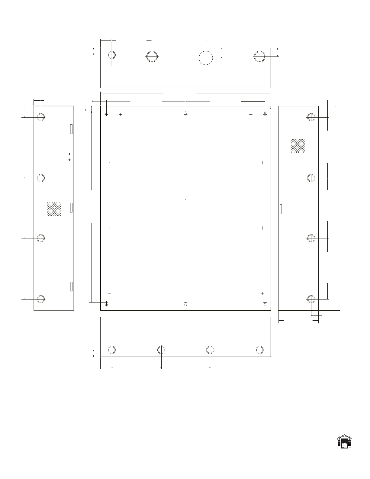
T3CVK77F20 (Trove3) Enclosure Dimensions (H x W x D approximate):
(50.8mm)
1.25” (31.8mm)
2.00” (50.8mm) 7.12” (222.3mm)
9.5” (241.3mm) 9.5” (241.3mm)
36.12” x 30.125” x 7.06” (917.5mm x 768.1mm x 179.3mm)
2.00” (50.8mm)10.75” (273.1mm)10.75” (273.1mm) 10.62” (269.8mm)
1.25” (31.8mm)
1.25” (31.8mm)
1.07”
(27.2mm)
1.10” (27.9mm)
G
G
33.63” (854.2mm)
30.12” (768.1mm)
14.01” (355.9mm)
1.78” (45.2mm)
14.01” (355.9mm)
1.55” (39.4mm)
2” (50.8mm)
10.75” (273.1mm)10.75” (273.1mm) 10.62” (269.8mm)
36.12” (917.5mm)
7.06” (179.3mm)
1.25” (31.8mm)
2”
8.75” (222.3mm)
8.62” (219mm)
8.75” (222.3mm)
Altronix is not responsible for any typographical errors.
140 58th Street, Brooklyn, New York 11220 USA | phone: 718-567-8181 | fax: 718-567-9056
web site: www.altronix.com | e-mail: info@altronix.com | Lifetime Warranty | Made in U.S.A.
IITrove CDVI Kits K04S
- 12 - Trove CDVI Kits
MEMBER
 Loading...