

Page 1
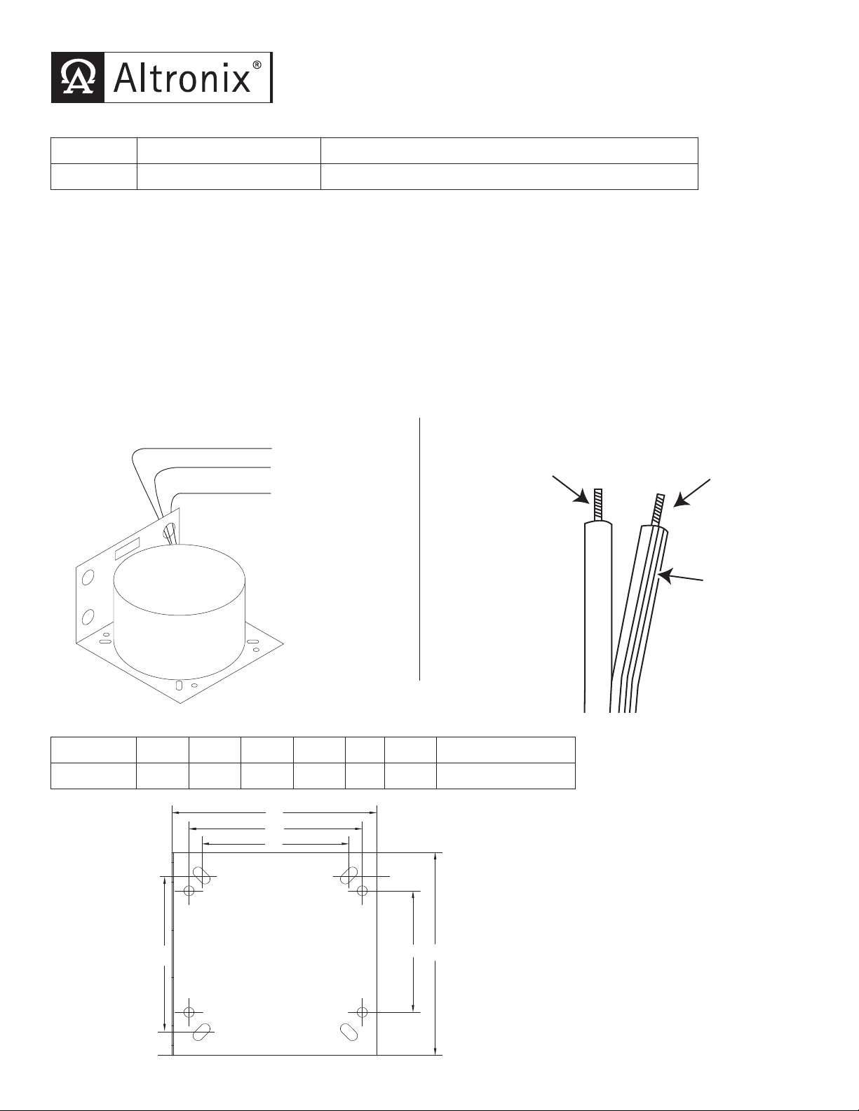
T2428300 - Open Frame Transformer
XFMR
Common
28VAC
24VAC
Yellow
Black
Brown
Connects
to Black Lead
Connects
to White Lead
Textured
Two-Wire
Line Cord
A
B
C
D
EF
Specification Chart:
Model # Input Output
T2428300 115VAC 50/60Hz, 2.7 amp. 24VAC/300VA (12.5 amp) or 28VAC/300VA (10 amp)
Installation Instructions:
1. Mount transformer in desired location/enclosure.
2. If it is desired to install strain relief (supplied), refer to Strain Relief Installation Instructions (Fig. 4 - Fig. 6, pg. 2).
3. Connect 115VAC power to the primary wires as shown in the Wiring Configuration and Line Cord Installation
belo
w (Fig. 1 and Fig. 2).
4.
Connect the line cord to black and white flying leads of transformer.
5. Measure output voltage before connecting devices. This helps avoid potential damage.
6. Connect 24VAC or 28VAC devices to secondary terminals on the transformer. For 24VAC configuration use brown
and yellow leads, for 28VAC configuration use brown and black leads (Fig. 1).
WARNING: This installation should be made by qualified service personnel and should
conform to all local codes and in accordance with the National Electrical Codes.
Wiring Configuration:
Fig. 1
Line Cord Installation:
Fig. 2
Transformer Bracket Dimensions Chart:
Model # A B C D E F Approx. Ship Wt.
T2428300 3.9” 5.15” 4.35” 3.7” 5.1” 3.05” 14.15 lbs.
Fig. 3
Page 2
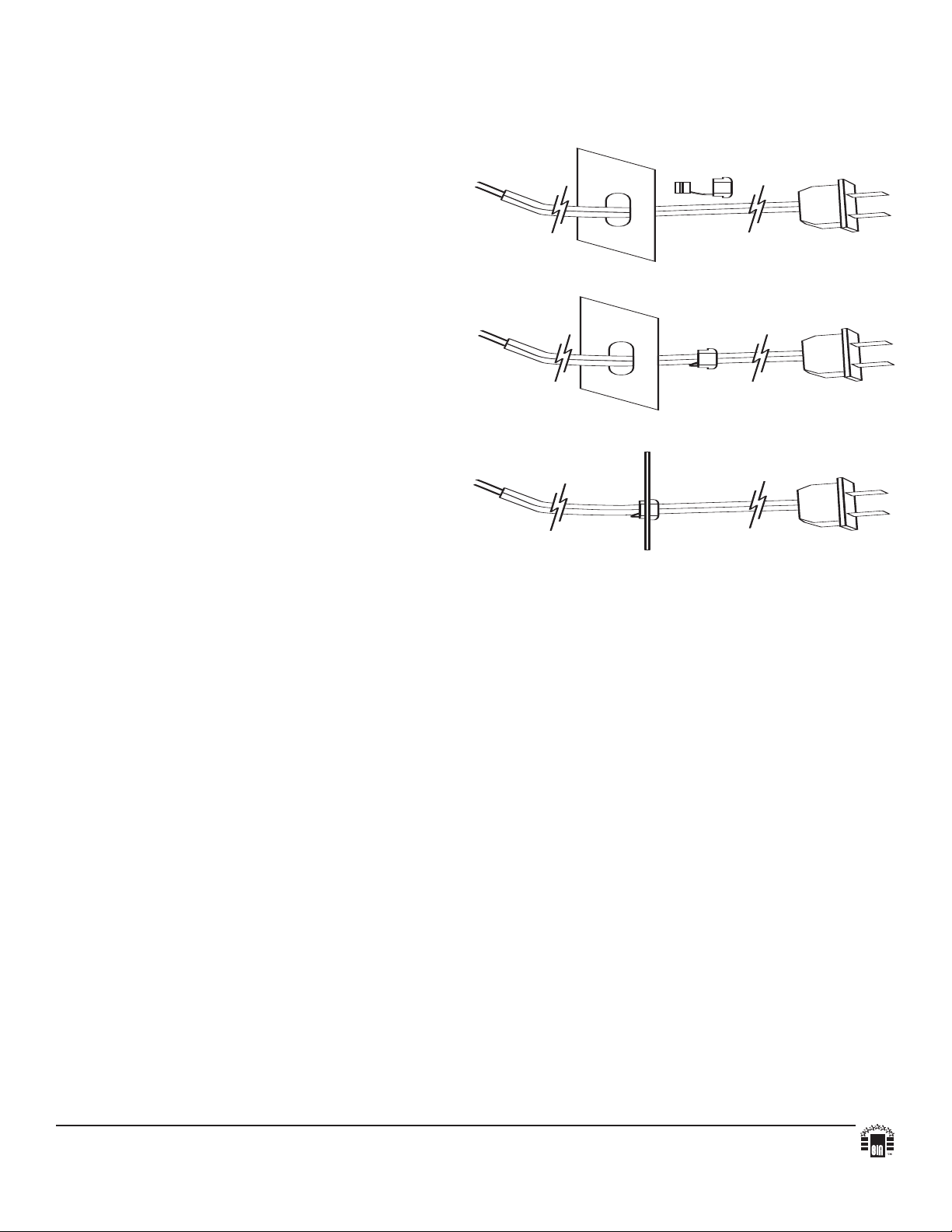
Strain Relief Installation Instructions:
Strain Relief
Bushing
Metal
Bracket
2-Wire Line Cord
2-Wire Line Cord
Strain Relief
Bushing
Metal
Bracket
2-Wire Line Cord
Strain Relief
Bushing
Metal
Bracket
Wiring methods shall be in accordance with the National Electrical Code/NFPA 70/NFPA 72/ANSI, and with all local
codes and authorities having jurisdiction. Product is intended for indoor use only.
The line cord option should be used when the equipment needs to be removed for maintenance or servicing.
1. Push 2-wire line cord through designated line cord
access opening on the bottom of enclosure
(Fig. 4, on right).
2. Place Strain Relief Bushing onto 2-wire line cord, by clamping down on both sides of Strain Relief Bushing
(using the He
yco 3962 Strain Relief Plier),
(Fig. 5, on right).
Note: Take care not to damage the 2-wire line cord.
3.
Push Strain Relief Bushing w/2-wire line cord through the designated line cord access opening on the bottom
of enclosure, allowing proper slack for hookup
(approximately 6" to 8"). When positioning the
2-wire line cord in the enclosure make sure that it
does not come into direct contact with the transformer,
(Fig. 6, on right).
Fig. 4
Fig. 5
Fig. 6
Altronix is not responsible for any typographical errors. Product specifications are subject to change without notice.
140 58th Street, Brooklyn, New York 11220 USA, 718-567-8181, fax: 718-567-9056
website: www.altronix.com, e-mail: info@altronix.com, Made in U.S.A.
IIT2428300 - Rev. 010808 B11H
MEMBER
 Loading...