

Page 1
SMP7 - Power Supply/Charger
Overview:
SMP7 power supply/charger converts low voltage AC input into 12VDC or 24VDC @ 6 amp of continuous supply
current (refer to specifications). This general purpose power supply has a wide range of applications for access control,
security and CCTV system accessories that require additional power.
Specifications:
Input:
• 28VAC/175VA.
Output:
• 12VDC or 24VDC selectable output.
• 6 amp continuous supply current.
• Filtered and electronically regulated output.
• Thermal overload and short circuit protection.
Battery Backup:
Built-in charger for sealed lead acid or gel type batteries.
•
• Maximum charge current 600mA.
• Automatic switch over to stand-by battery when AC fails.
Additional Featur
• AC input and DC output LED indicators.
• Includes batter
Board Dimensions (approximate): 7”L x 4.25”W x 1.75”H
* Specified at 25˚ C ambient.
es:
y leads.
Voltage Output/T
Output VDC Switch Position Max. Load DC Transformer Requirements
12VDC
24VDC SW1 Open 6 amp 24VAC or 28VAC / 175VA ( T2428175)
Installation Instructions:
The SMP7 should be installed in accordance with The National Electrical Code and all applicable Local Regulations.
1. Mount the SMP7 in desired location/enclosure.
2. Set the SMP7 to the desired DC output voltage by setting the switches to the appropriate positions
olta
V
er to
(
ef
r
3. Connect proper transformer to terminals marked [AC] (
Use 18 AWG or larger for all power connections (Battery, DC output).
Measure output v
4.
5. Connect devices to be powered to terminals marked [+ DC -].
6. When the use of stand-by batteries are desired, they must be lead
acid or gel type. Connect battery to terminals marked [+ BAT -].
(battery leads included). Use two (2) 12VDC batteries connected in series for 24VDC operation.
Note: When batteries are not used a loss of
LED Diagnostics:
Red (DC)
ON ON Normal operating condition.
ON OFF Loss of AC, Stand-by battery supplying power.
OFF ON No DC output. Short circuit or thermal overload condition.
OFF OFF Loss of AC. Discharged or no stand-by battery. No DC output.
ransformer Selection Table:
(Recommended Altr
SW 1 Closed 6 amp 24VAC or 28VAC / 175VA ( T2428175)
e Output/Transformer Selection Table
g
oltage before connecting devices. This helps avoid potential damage.
A
Green (AC) Power Supply Status
).
refer Voltage Output/Transformer Selection Table).
C will result in the loss of output voltage.
onix Part #’s)
Page 2
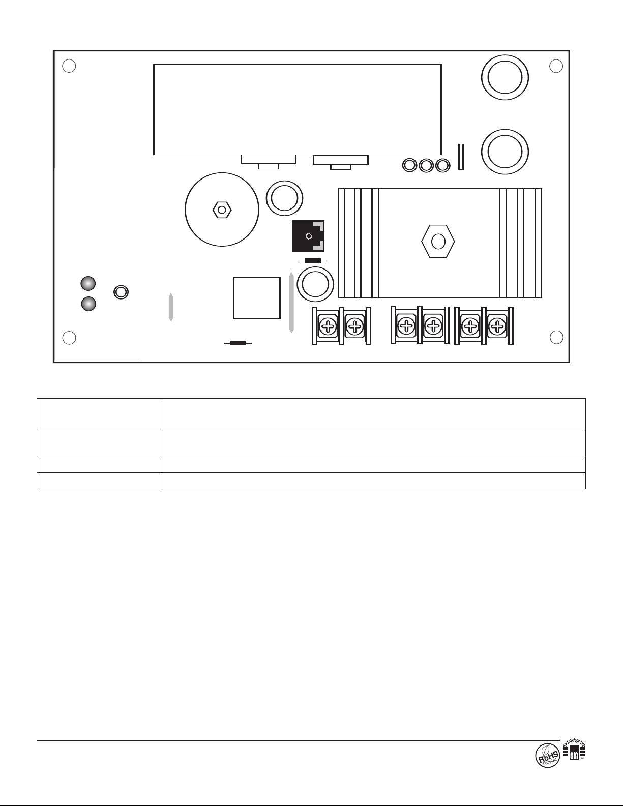
Terminal Identification:
+
D C ---
AC
AC AC
+
BAT ---
OPEN = 24V SW1 CLOSED = 12V
DC
RLY1
PTC
J2
Terminal Function/Description
Legend
AC/AC Low voltage AC input (28VAC / 175VA).
Altronix model # T2428175
rent.
-- 12VDC or 24VDC @ 6 amp continuous suppl
+ DC
y cur
+ BAT -- Stand-by battery connections. Maximum charge rate 600mA.
Altronix is not responsible for an
140 58th Street, Brooklyn, New York 11220 USA, 718-567-8181, fax: 718-567-9056
website: www.altronix.com, e-mail: info@altronix.com, Lifetime Warranty, Made in U.S.A.
IISMP7 - Rev. 110606 K06F
raphical errors. Product specifications are subject to change without notice.
g
y typo
MEMBER
 Loading...