

Page 1
SMP5CTX Series
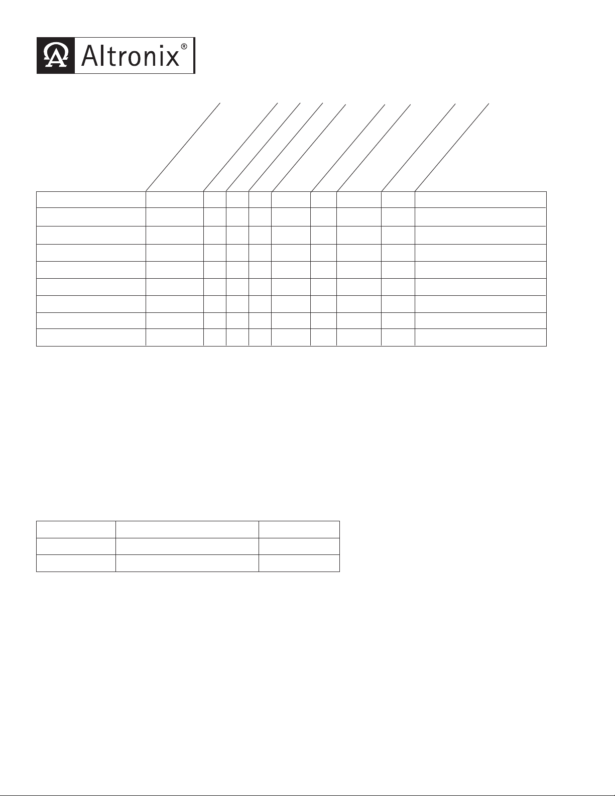
SMP5CTX Series Power Supply Configuration Reference Chart:
vidual Output
Model Number
Altronix
SMP5CTX - 1 - - - - .95 / .5 4 13.5”H x 13”W x 3.25”D
SMP5PMCTX - 1 - - - x .95 / .5 4 13.5”H x 13”W x 3.25”D
SMP5PMCTXX - 1 - - - x .95 / .5 4 15.5”H x 12”W x 4.5”D
SMP5PMP4 PD4 4 x - 3.5 x .95 / .5 4 13.5”H x 13”W x 3.25”D
SMP5PMP4CB PD4CB 4 - x 2.5 x .95 / .5 4 13.5”H x 13”W x 3.25”D
SMP5PMP8 PD8
SMP5PMP8CB PD8CB 8 - x 2.5 x .95 / .5 4 13.5”H x 13”W x 3.25”D
SMP5PMP16 PD16W 16 x - 3.5 x .95 / .5 4 13.5”H x 13”W x 3.25”D
SMP5PMP16CB PD16WCB 16 - x 2.5 x .95 / .5 4 13.5”H x 13”W x 3.25”D
Distribution
Accessory Power
Module(s)
Number of Outputs
Fused Outputs
PTC Outputs
Indi
Rating (amp)
Supervised
8 x - 3.5 x .95 / .5 4 13.5”H x 13”W x 3.25”D
Input Current (amp)
115VAC/230VAC
12/24VDC Total
Enclosure Dimensions
Output Current (amp)
Overview:
These units will convert a 115VAC or 230VAC, 50Hz/60Hz input, into a regulated 12VDC or 24VDC output up to 4
amps of continuous load current (see specifications).
Specifications:
• Universal 115/230VAC input.
• Maximum charge current .5 amp.
• Filtered and electronically regulated outputs.
• Built-in charger for sealed lead acid or gel type batteries.
• Automatic switch over to stand-by battery when
AC fails (zero voltage drop).
• AC input and DC output LED indicators.
• Short circuit and thermal overload protection.
• Complete with power supply, power distribution module
hen applicab
(w
• Power on-off switch.
Supervised Models Only:
• AC fail supervision (form "C" contacts).
• Low battery supervision (form "C" contacts).
le), enclosure, cam lock & battery leads.
Power Supply Voltage Output Specifications: *
Output VDC Switch Position Max. Load DC
12VDC SW1 - Closed
24VDC SW1 - Open
*Specified at 25˚ C ambient.
(Fig. 1b, pg. 3) 4 amp
(Fig. 1b, pg. 3) 4 amp
Installation Instructions:
The unit should be installed in accordance with The National Electrical Code and all applicable Local Regulations.
1. Mount the unit in desired location.
2. Set SW1 on the power supply board to the desired DC output voltage
(Power Supply Voltage Output Specification Chart).
wer to terminals marked [L & N], connect ground to terminal marked [G] (if used).
C po
Connect
3.
Use 18
Use 22 AWG to 18 AWG for power limited circuits (AC Fail/Low Battery reporting).
A
WG or lar
A
ger for all po
er connections (Batter
w
y, DC output).
- 1 -
Page 2
4
. Connect devices to be powered:
a. For Power Supply Board connect to terminals marked [– DC + ].
b
. For Power Distribution Module(s) connect devices to be powered to terminal pairs 1 to 4 marked
[1P & 1N thru 4P & 4N]
[1P & 1N thru 16P & 16N]
(Fig. 2, pg. 4) or 1 to 8 marked [1P & 1N thru 8P & 8N] (Fig. 3, pg. 4) or 1 to 16 marked
(Fig. 4, pg. 4) carefully observing correct polarity.
Note: Measure output voltage before connecting devices. This helps avoid potential damage.
*Note: Power switch is used to disconnect the L (HOT) terminal from the rest of the board. When servicing the unit,
AC mains should be removed.
5. When using stand-by batteries, they must be lead acid or gel type. Connect battery to terminals marked [– BAT +]
(battery leads included). Use two (2) 12VDC batteries connected in series for 24VDC operation.
Note: When batteries are not used a loss of AC will result in the loss of output voltage.
6. Connect appropriate signaling notification devices to AC Fail & Low Bat supervisory relay outputs
marked [NC, C, NO]
(Fig. 1a, pg. 3).
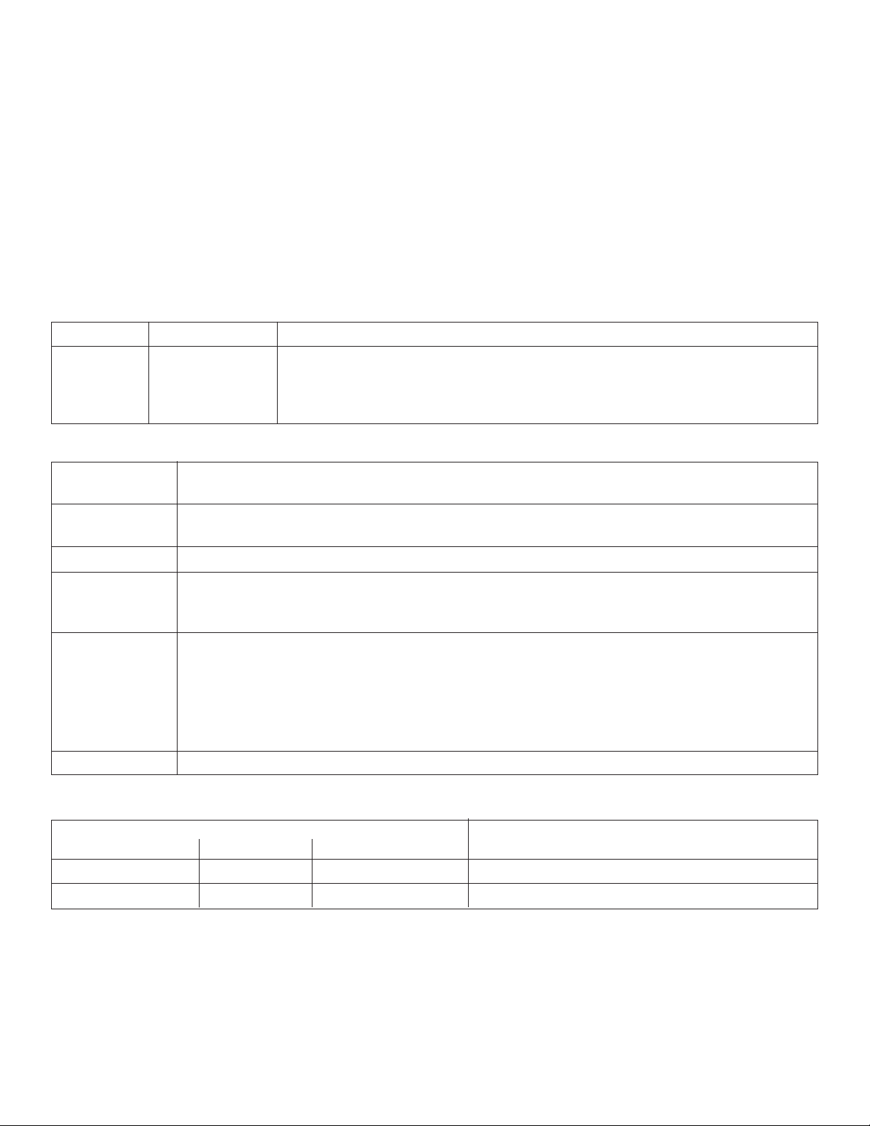
LED Diagnostics:
Red (DC) Green (AC) Power Supply Status
ON ON Normal operating condition
ON OFF Loss of AC, Stand-by battery supplying power
OFF ON No DC output
OFF OFF Loss of AC. Discharged or no stand-by battery. No DC output.
Terminal Identification:
Terminal Function/Description
Legend
L, G, N
Connect 115V
L to Hot, N to Neutral, G to g
– DC + 12VDC / 24VDC @ 4 amp continuous non-power limited output.
AC FAIL Used to notify loss of AC power, e.g. connect to audible device or alarm
NC, C, NO panel. Relay normally energized when AC power is present.
Contact rating 1 amp @ 120VAC / 28VDC
Low Batter
NC, C, NO
y Used to indicate low battery condition, e.g. connect to alarm panel.
. Rela
y nor
Contact rating 1 amp @ 120VAC / 28VDC
w batter
Lo
12VDC output threshold set @ approximately 10.5VDC,
24VDC output threshold set @ appro
– BAT + Stand-by battery connections. Maximum charge rate .5 amp.
AC/230VAC to these terminals:
round (if used).
mally energized when DC power is present.
y threshold:
ximatel
y 21VDC.
PD4/PD4CB/PD8/PD8CB/PD16W/PD16WCB - Power Distribution Module
erminal Legend Function/
T
PD4/PD4CB
PD8/PD8CB
PD16W/PD16WCB
1P to 4P 1P to 8P 1P to16P Positive DC power outputs.
1N to 4N 1N to 8N 1N to 16N Negative DC power outputs.
- 2 -
Description
Page 3

Power
Distribution
Module(s)
CAUTION: De-energize unit prior to servicing. For continued protection against fire hazard
replace fuse with the same type and rating 5A, 250V.
Green
Lead
Wire
Strap
(from
Enclosure
to Door)
115/230VAC
power
mains
INPUT
LOW BAT
N
C C NO NC C NC
A
C FAIL
SW1:
24V - OPEN
12V - CLOSED
CAUTION: When power supply board is set for 12VDC use only one (1) 12VDC
stand-by battery.
Keep power limited wiring separate from non-power limited. Use minimum .25" spacing.
12VDC Rechargeable Battery
(optional)
12VDC Rechargeable Battery
(optional)
L G N
OFF ON
OPEN - 24VDC
CLOSED - 12VDC
L
OW BAT
NC C NO NC C NO
AC FAIL
---BAT + --- DC +
AC DC
5A250V
Fig. 1
Fig. 1a
Fig. 1b
- 3 -
Page 4

INPUT
LED
1P, 2P, 3P, 4P = FUSED OUTPUTS
1N, 2N, 3N,4N = COMMON OUTPUTS
F
1
F1
F
2 F3 F4
COMMON POWER OUTPUTS
1P
1N
2
P
2N
3P
3N
4P
4N
DC Output to devices
From Power Supply
Board
(
Factory Installed)
Used on
PTC Models
N
CO MM ON P OWE R O UT PU TS
P
F
US ED PO WE R O UTP UT S
1 2 3 4 5 6 7 8
1
D1
INPUT
R1
LED
DC Output to devices From Power Supply
Board
(
Factory Installed)
Power Distribution Module(s):
common
outputs
protected
outputs
P
N
NPS
XFMR Input
1
2345678
9
10 11 12 13 14 15 16
P
N
3.5A 250V
For continuous protection against risk of fire
replace fuses with same type and rating.
Used on
PTC Models
Fig. 2 Fig. 3
Fig. 4
- 4 -
Page 5

5.10"
6.5625"
3.25"3.25"
5.10"
5.10"
3.25"
1.00"10.50"1.00"
1.00"
1.00"
1
.40"
1.20"
1.40"
1
.20"
0
.75
"
0.75" 11.00"
1
2.50"
3.25"
0.9375"
0.9375"
1
.40" 4.85" 4.85" 1.40"
1.20"
Bottom
Top
RightLeft
Enclosure Dimensions for:
• SMP5PMCTX • SMP5PMP4 • SMP5PMP4CB
• SMP5PMP8 • SMP5PMP8CB • SMP5PMP16 • SMP5PMP16CB
13.5”H x 13”W x 3.25”D
Enclosure accommodates up to two (2) 12VDC/7AH batteries.
Also available to accommodate up to two (2) 12VDC/12AH batteries (please contact Altronix).
- 5 -
Page 6

1
2.230"
15.500"
1.100"
0.910"
1.100"
0.910"
0.790"
1.100"
1.500"
1.250"
5.000"
1.250"
1.500"
4.615"
4.615"1.500"
1.750"
1
.500"
4
.615"
4.615"1.500"
1.750"
4
.500"
4
.500"
1.250"
1.500"
5.000"
2
.000"
2.000"
1.250"
1.375"
1.125"
Enclosure Dimensions for:
• SMP5PMCTXX
15.5”H x 12”W x 4.5”D
Enclosure accommodates up to two (2) 12VDC/12AH batteries.
- 6 -
Page 7

Notes:
- 7 -
Page 8

Notes:
Altronix is not responsible for any typographical errors. Product specifications are subject to change without notice.
ork 11220 USA, 718-567-8181, f
Y
w
140 58th Street, Brookl
web site: www.altronix.com, e-mail: info@altronix.com, Made in U.S.A.
IISMP5PMCTX - Rev. 093003 H02J
yn, Ne
ax: 718-567-9056
- 8 -
MEMBER
 Loading...