

Altronix SMP7CTX, SMP7PMP8, SMP7PMCTXX, SMP7PMP4, SMP7PMCTX Installation Manual
...
SMP7CTX Series
Power Supply/Charger
Installation Guide
Models Include:
SMP7CTX
SMP7PMCTX
SMP7PMCTXX
- Single Output.
SMP7PMP4
- Four (4) Fuse Protected Outputs.
SMP7PMP8
- Eight (8) Fuse Protected Outputs.
SMP7PMP16
- Sixteen (16) Fuse Protected Outputs.
For a red enclosure add an “R” suffix to the part #, e.g. SMP7CTXR
Rev. 011604
SMP7PMP4CB
- Four (4) PTC Protected Outputs.
SMP7PMP8CB
- Eight (8) PTC Protected Outputs.
SMP7PMP16CB
- Sixteen (16) PTC Protected Outputs.
More than just power.
TM
Altronix SMP7CTX Series power supply/chargers convert a 115VAC, 60Hz input into a regulated 12VDC or
ON - 12V
24VDC output with up to 6A of continuous load current (see specifications).
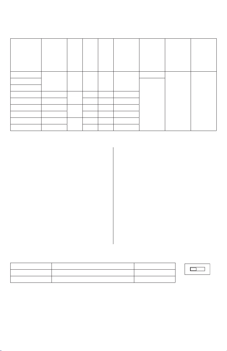
SMP7CTX Series Power Supply Configuration Reference Chart:
Overview:
Accessory
Altronix
Model Number
SMP7CTX
SMP7PMCTX
SMP7PMCTXX
SMP7PMP4
SMP7PMP4CB
SMP7PMP8
SMP7PMP8CB
SMP7PMP16
SMP7PMP16CB
Power
Distribution
Module(s)
– 1 – – 6A
PD4
PD4CB –
PD8
PD8CB –
PD16W
PD16WCB –
Number
of Outputs
4
8
16
Fused Outputs
P
P
P
Specifications:
Input:
• Input 115VAC, 60Hz, 2.5A.
Output:
• 12VDC or 24VDC selectable output.
• 6A supply current.
• Filtered and electronically regulated outputs.
• Short circuit and thermal overload protection.
Battery Backup:
• Built-in charger for sealed lead acid or
gel type batteries.
• Maximum charge current 0.7A.
• Zero voltage drop when switching over to
battery backup.
Features:
• Power ON/OFF switch.
Supervision (select models):
• AC fail supervision (form “C” contacts).
• Battery presence and low battery supervision
(form “C” contacts).
Individual
Output
PTC Outputs
(auto-resettable)
Rating (A) Supervised
– 3.5A
P
– 3.5A
P
– 3.5A
P
2.5A
2.5A
2.5A
–
P
115VAC,
60Hz
Input
Current (A)
2.5A 6A
Visual Indicators:
• AC input and DC output LED indicators.
Electrical:
• Operating temperature: 0ºC to 49ºC ambient.
Mechanical:
• Enclosure Dimensions (H x W x D approx.):
SMP7CTX, SMP7PMCTX, SMP7PMP4,
SMP7PMP4CB, SMP7PMP8, SMP7PMP8CB,
SMP7PMP16, SMP7PMP16CB:
13.5” x 13” x 3.25” (342.9mm x 330.2mm x 82.6mm)
- Accommodates up to
two (2) 12VDC/7AH batteries.
SMP7PMCTXX:
15.5” x 12” x 4.5” (393.7mm x 304.8mm x 114.3mm)
- Accommodates up to
two (2) 12VDC/12AH batteries.
12/24VDC
Total
Output
Current (A)
Power Supply Voltage Output Specifications:*
Output VDC Switch Position Max. Load DC
12VDC SW1 - ON (Fig. 1c, pg. 5) 6A
24VDC SW1 - OFF (Fig. 1c, pg. 5) 6A
*Specified at 25˚C ambient.
- 2 - SMP7CTX Series
ON
OFF - 24V

Wiring methods shall be in accordance with the National Electrical Code/NFPA 70/NFPA 72/ANSI, and with
Installation Instructions:
all local codes and authorities having jurisdiction. Product is intended for indoor use only.
1. Mount unit in the desired location. Mark and predrill holes in the wall to line up with the top two keyholes
in the enclosure. Install two upper fasteners and screws in the wall with the screw heads protruding. Place
the enclosure’s upper keyholes over the two upper screws; level and secure. Mark the position of the lower
two holes. Remove the enclosure. Drill the lower holes and install the three fasteners. Place the enclosure’s
upper keyholes over the two upper screws. Install the two lower screws and make sure to tighten all screws
(Enclosure Dimensions, pgs. 7, 8). Secure enclosure to earth ground.
2. Slide [Power ON/OFF] switch t o OFF position.
3. Set SW1 on the power supply board to the desired DC output voltage (Fig. 1c, pg. 5)
(Power Supply Voltage Output Specification Chart).
4. Connect AC power to the terminals marked [L & N], connect ground to the green flying lead (Fig. 1, pg. 5).
Use 18 AWG or larger for all power connections (Battery, DC output).
Use 22 AWG to 18 AWG for power-limited circuits (AC Fail/Low Battery reporting).
5. Slide [Power ON/OFF] switch to ON position.
6. Measure output voltage before connecting devices. This helps avoiding potential damage.
Keep power-limited wiring separate from non power-limited wiring (115VAC, 60Hz Input,
Battery Wires). Minimum 0.25” spacing must be provided.
CAUTION: Do not touch exposed metal parts.
Shut branch circuit power before installing or servicing equipment.
There are no user serviceable parts inside. Refer installation and servicing to qualified service personnel.
7. Slide [Power ON/OFF] switch t o OFF position.
8. Connect devices to be powered:
a. For Power Supply Board connect to the terminals marked [– DC +].
b. For Power Distribution Module(s) connect devices to be powered to the terminal pairs 1 to 4 marked
[1P & 1N] through [4P & 4N] (Fig. 2, pg. 6), 1 to 8 marked [1P & 1N] through [8P & 8N] (Fig. 3, pg. 6),
or 1 to 16 marked [1P & 1N] through [16P & 16N] (Fig. 4, pg. 6), carefully observing correct polarity.
Note: Power switch is used to disconnect the L (HOT) terminal from the rest of the board (Fig. 1a, pg. 5).
When servicing the unit, AC mains should be removed.
9. When using stand-by batteries, they must be lead acid or gel type.
Connect battery to the terminals marked [– BAT +] (battery leads included).
12VDC operation: Use one (1) 12VDC battery.
24VDC operation: Use two (2) 12VDC batteries connected in series.
Note: When batteries are not used, a loss of AC will result in the loss of output voltage.
For supervised models only:
10. Connect appropriate signaling notification devices to AC Fail and Low Bat supervisory relay outputs
marked [NC, C, NO] (Fig. 1b, pg. 5).
11. Slide [Power ON/OFF] switch to ON position.
LED Diagnostics:
Power Supply Board
Red (DC) Green (AC) Power Supply Status
ON ON Normal operating condition.
ON OFF Loss of AC. Stand-by battery is supplying power.
OFF ON No DC output.
OFF OFF Loss of AC. Discharged or no stand-by battery. No DC output.
Power Distribution Module
Green Power Distribution Module Status
ON Normal operating condition.
OFF No Power Output.
SMP7CTX Series - 3 -
 Loading...