

Page 1
Installation Instructions:
The units should be installed in accordance with The National Electrical Code and all applicable Local Regulations.
1. Mount the unit in desired location.
2. Connect AC power to terminals marked [L & N], connect ground to terminal marked [G] (if used).
Use 18 AWG or larger for all power connections (Battery, DC output).
3. Measure output voltage before connecting devices. This helps avoid potential damage.
4. Connect devices to be powered:
a. For Power Supply Board connect to terminals marked [+ DC -].
b. For Power Distribution Module(s) connect devices to be powered to terminal pairs 1 to 4 marked
[1P & 1N thru 4P & 4N] (Fig. 2, pg. 3) or 1 to 8 marked [1P & 1N thru 8P & 8N] (Fig. 3, pg. 3) carefully
observing correct polarity.
5. When using stand-by batteries, they must be lead acid or gel type. Connect battery to terminals marked [- BAT +]
(battery leads included).
Note: When batteries are not used a loss of AC will result in the loss of output voltage.
6. For Supervised Models Only.
Connect appropriate signaling notification devices to AC Fail & Low Bat supervisory relay outputs marked
[N0 C, NC] (Fig. 1A, pg. 3).
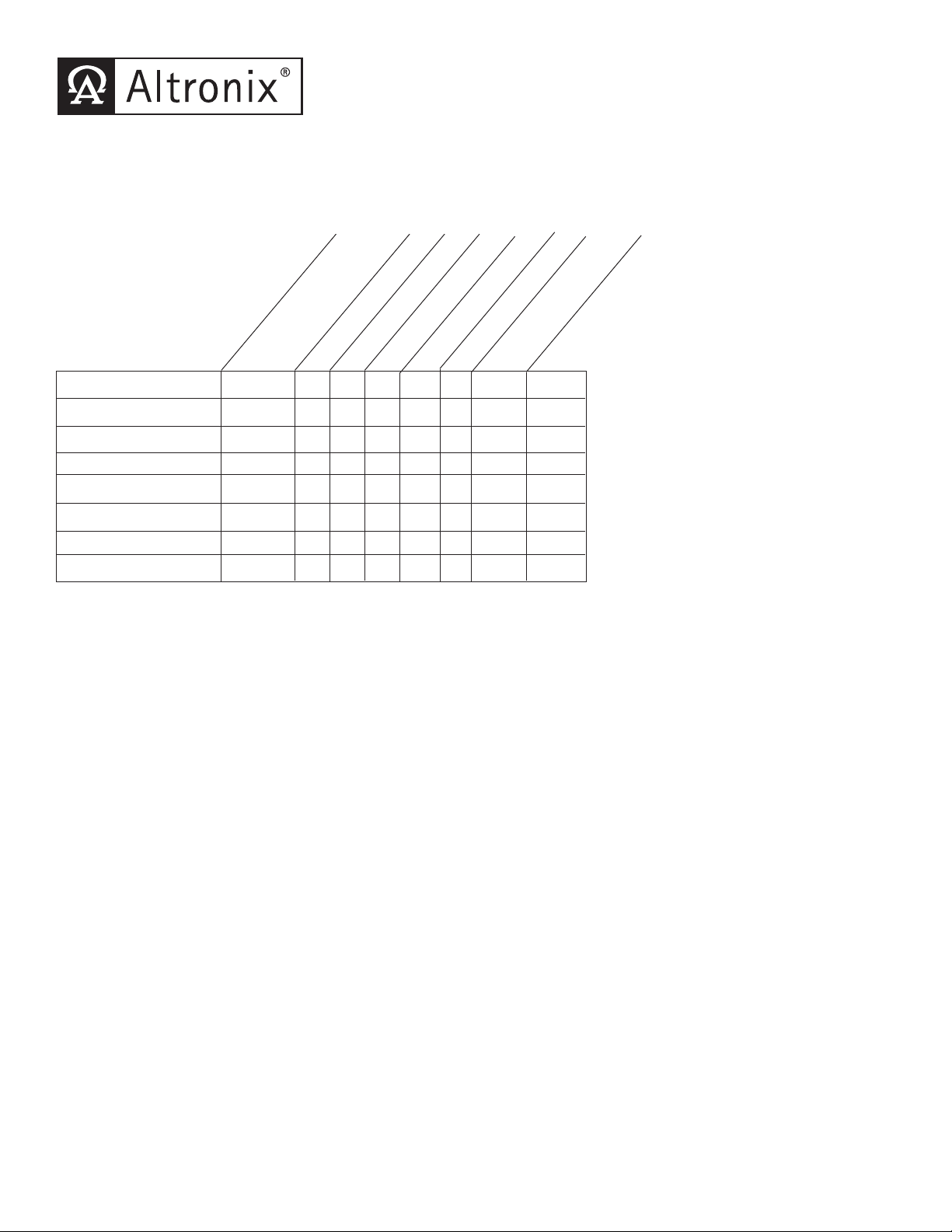
SMP10C24X -1--10-2.7 10
SMP10PMC24X -1--10x2.7 10
SMP10PM24P4 PD4 4 x - 3.5 x 2.7 10
SMP10PM24P4CB PD4 4 - x 2.5 x 2.7 10
SMP10PM24P8 PD8 8 x - 3.5 x 2.7 10
SMP10PM24P8CB PD8 8 - x 2.5 x 2.7 10
SMP10PM24P16 PD8 16 x - 3.5 x 2.7 10
SMP10PM24P16CB PD8 16 - x 2.5 x 2.7 10
Altronix
Model Number
Accessory Power
Distribution
Module(s)
Number of Outputs
Fused Outputs
PTC Outputs
Output Rating (amp)
115VAC / 60Hz
Input Current (amp)
24VDC Total Output
Current (amp)
SMP1024X Series Power Supply Configuration Reference Chart:
Overview:
These units will convert a 115VAC / 60Hz input, into a regulated 24VDC output at up to 10 amps of continuous supply
current (see specifications).
• Maximum charge current .7 amp.
• Filtered and electronically regulated outputs.
• Built-in charger for sealed lead acid or gel type batteries.
• Automatic switch over to stand-by battery when
AC fails (zero voltage drop).
• AC input and DC output LED indicators.
• Short circuit and thermal overload protection.
• Complete with power supply, power distribution module
(when applicable), enclosure, cam lock & battery leads.
Supervised models only:
• AC fail supervision (form "C" contacts).
• Low battery supervision (form "C" contacts).
- 1 -
SMP1024X Series
Supervised
Specifications:
Page 2

LED Diagnostics:
OLS250/OLS257 - Power Supply Board
Red (DC) Green (AC) Power Supply Status
ON ON Normal operating condition
ON OFF Loss of AC, Stand-by battery supplying power
OFF ON No DC output
OFF OFF Loss of AC. Discharged or no stand-by battery. No DC output.
PD4/PD4CB/PD8/PD8CB - Power Distribution Module
Green Power Distribution Module Status
ON Normal operating condition.
Terminal Identification:
OLS250/OLS257 - Power Supply Board
Terminal Function/Description
Legend
L, G, N Connect 115VAC to these terminals:
L to Hot, N to Neutral, G to ground (if used).
+ DC - 24VDC @ 10 amp continuous outputs.
*AC FAIL Used to notify loss of AC power, e.g. connect to audible device or alarm
N.O., C, N.C. panel. Relay normally energized when AC power is present.
Contact rating 1 amp @ 120VAC / 28VDC
*Low Battery Used to indicate low battery condition, e.g. connect to alarm panel.
N.O., C, N.C. Relay normally energized when DC power is present.
Contact rating 1 amp @ 120VAC / 28VDC
Low battery threshold:
24VDC output threshold set @ approximately 21VDC.
- BAT + Stand-by battery connections. Maximum charge rate .7 amp.
*Note: Supervised Models Only.
PD4/PD4CB/PD8/PD8CB - Power Distribution Module
Terminal Legend Function/
PD4/PD4CB PD8/PD8CB Description
1P to 4P 1P to 8P Positive DC power outputs.
1N to 4N 1N to 8N Negative DC power outputs.
- 2 -
Page 3

ALTRONIX CORP. MADE IN USA
BROOKLYN, NY 11220
INPUT
+ BAT --- + DC ---
DC
CAUTION: De-energize unit prior to servicing. For continued protection
against fire hazard replace fuses with the same type and rating.
Replace fuse cover before energizing:
Input Fuse rated @ 10 amp, 250VAC
Output Fuse rated @ 15 amp, 32VAC
Battery Battery
unswitched 115VAC power mains
Door
Wire Strap
(from
Enclosure
to Door)
Divider
Battery
connection
Fuse
Cover
BAT FAIL
NC C NO NC C NO
AC FAIL
BAT FAIL
NO C NC NO C NC
AC FAIL
Power Supply
Board
Power
Distribution
Module(s)
UT
T
O
CO
,
,
3
3
3N
s
y
U
C
s
Fig. 1
Fig. 2 Fig. 3
- 3 -
Fig. 1A
Power Distribution Module(s):
sed
on PT
Model
1P, 2P, 3P, 4P = FUSED OUTPUTS
1N
2N, 3N, 4N = COMMON OUTPUTS
1
RP.
NY 11220
F
P
NIX
LTR
ADE IN USA
ROOKLYN
POWER DISTRIBUTING UNI
INP
1
Used
on PTC
Models
123 4 5678
ALTRONIX CORP. MADE IN USA
BROOKLYN, NY 11220
P
FUSED POWER OUTPUTS
N
COMMON POWER OUTPUTS
PD8
D1
R1
LED
INPUT
DC Output to device
From Power Suppl
Board
(Factory Installed)
DC Output to devices
From Power Supply
Board
(Factory Installed)
Page 4

Altronix is not responsible for any typographical errors. Product specifications are subject to change without notice.
Altronix Corp.
140 58th Street, Brooklyn, New York 11220 USA, 718-567-8181, fax: 718-567-9056
web site: www.altronix.com, e-mail: info@altronix.com, Made in U.S.A.
IISMP10C24X - Rev. 102003 C11D
.875"
1"
0
00
0
10.75"
1.5"
6"
10.5"
2"
0
1.25"
4.5"
12"
15.5"
4.5"
4.5"
1.25"
1.25"
14.25"
13.5"
10"
6.625"
TOP & BOTTOM
Enclosure Dimensions for:
15.5”H x 12”W x 4.5”D
Enclosure accomodates up to two (2)
12VDC/12AH batteries.
- 4 -
MEMBER
 Loading...