

Page 1

Rack Mount Series
UL Listed CCTV Power Supplies
Installation Guide
Models Include:
• R2432300UL • R2432300ULCB
- 24VAC @ 12.5A (300VA) - 24VAC @ 12.5A (300VA)
or 28VAC @ 10A (280VA). or 28VAC @ 10A (280VA).
- Thirty-two (32) Fuse Protected Outputs. - Thirty-two (32) PTC Protected Outputs.
• R2432600UL • R2432600ULCB
- 24VAC @ 25A (600VA) - 24VAC @ 25A (600VA)
or 28VAC @ 20A (560VA). or 28VAC @ 20A (560VA).
- Thirty-two (32) Fuse Protected Outputs. - Thirty-two (32) PTC Protected Outputs.
Rev. 020504
Page 2
Overview:
These Altronix Rack Mount CCTV Power Supplies provide 24VAC or 28VAC distributed via thirty-two (32) fuse or PTC
protected outputs for powering CCTV cameras, heaters and other video accessories.
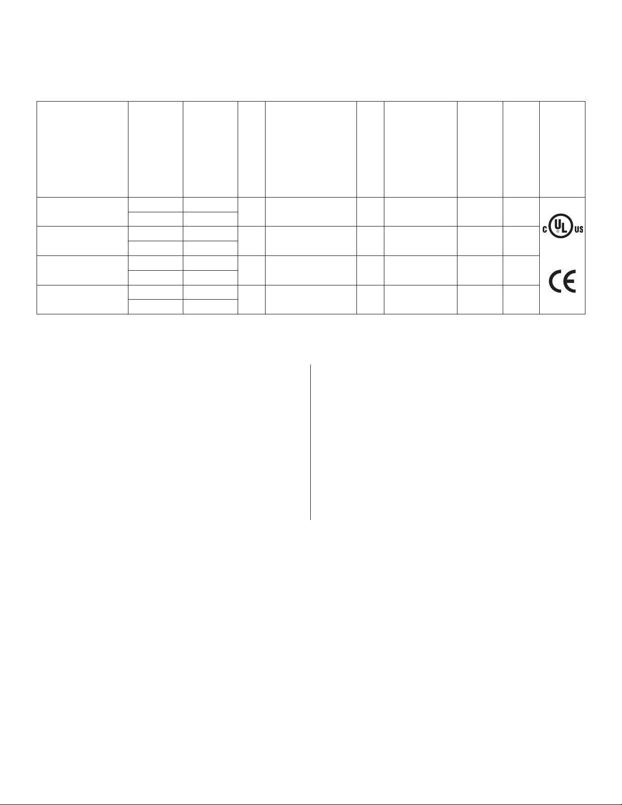
Thirty-two (32) Output Rack Mount Configuration Reference Chart:
Altronix
Output Voltage
Model Number
R2432300UL
R2432300ULCB
R2432600UL*
R2432600ULCB*
*24VAC models: Outputs 1-16 provide 12.5A (300VA) max. Outputs 17-32 provide 12.5A (300VA) max.
*28VAC models: Outputs 1-16 provide 10A (280VA) max. Outputs 17-32 provide 10A (280VA) max.
(VAC)
24VAC 12.5A
28VAC 10A
24VAC 12.5A
28VAC 10A
24VAC 25A
28VAC 20A
24VAC 25A
28VAC 20A
Total Output
Current (Power)
Number of
Outputs
32
32
32
32
PTC Protected
Outputs
(Class 2 power-
limited for Dry
locations, Class 3
for Wet locations).
P
P
Fuse Protected
Class 1 Outputs
Individual
Output Current
(max per output
P
P
3.5A 3.5A 3A
2.5A 3A
3.5A 3.5A 6A
2.5A 6A
not to exceed total
output current)
Fuse Ratings
115VAC 50/60Hz
Input Current
Agency
Listings
Specifications:
Agency Listings:
• UL Listed for Commercial CCTV Equipment (UL2044).
CUL Listed - CSA Standard C22.2 No.1-98, Audio,
Video and Similar Equipment.
CE - European Conformity
Input:
• 115VAC, 50/60Hz.
Output:
• Thirty-two (32) fuse or PTC protected outputs.
• 24VAC or 28VAC supply current.
• Outputs are rated @ 3.5A (fused) or 2.5 (PTC).
• Surge suppression.
Features:
• Thirty-two (32) individual power LED indicators.
• Illuminated master power disconnect circuit breaker
with manual reset.
• 3-wire grounded line cord.
• Removable terminal blocks with locking screw flange.
• Spare fuses provided.
Mechanical:
• 2U rack mount chassis for use in a standard
EIA 19” rack.
• Enclosure Dimensions (H x W x D approx.):
3.26” x 19.125” x 8.5” (83mm x 486mm x 216mm).
Installation Instructions:
1. The unit is factory set for 24VAC operation.
For 28VAC operation, adjust unit prior to mounting and applying power as follows:
a. Open bottom of the unit by removing six (6) screws (Rack Mechanical Drawing & Dimensions, pg. 4).
b. Change the wire position so that the black wire [28V] is connected to the terminal marked [P] and
the yellow wire [24V] is connected to the terminal marked [S] (Fig. 1d, pg. 3).
c. After securing all wires for proper voltage place bottom panel back on the unit and fasten with the six (6) screws.
2. Mount unit in the desired rack location (Space unit at least 3” from any video monitors). Do not obstruct side air vents.
3. Set power disconnect circuit breaker to the OFF position (Fig. 1c, pg. 3).
4. Plug power cord into a grounded 115VAC 50/60 Hz receptacle (Fig. 1b, pg. 3), ground should be connected
as indicated in (Fig. 1e, pg. 3).
5. Set power disconnect circuit breaker to the RESET (ON) position and measure output voltage before
connecting devices (Fig. 1c, pg. 3). This helps avoiding potential damage. All terminals with common
suffix (P) “1P, 2P...” are the same polarity.
6. Set power disconnect circuit breaker to the OFF position (Fig. 1c, pg. 3).
7. Connect devices to the removable terminal blocks marked [1P & 1N] through [8P & 8N] (Fig. 1a, pg. 3).
When wiring is completed on the terminal blocks, they can be locked down by tightening screw flanges.
8. Upon completion of the wiring, set power disconnect circuit breaker to the RESET (ON) position (Fig. 1c, pg. 3).
- 2 - R2432ULseries
Page 3

Fig. 1 Fig. 1a
Removable Terminal
Block
Fig. 1b Fig. 1c
RESET
Strain Relief
Line Cord
Circuit Breaker with
Illuminated
Power Disconnect
manual reset
PTC1
Used
on PTC
Models
N
P
S
AC Power
LED's
AC Power
LED's
AC Power
LED's
AC Power
LED's
N
N
P
P
S
S
XFMR*XFMR*
AC Power
LED's
AC Power
LED's
AC Power
LED's
AC Power
LED's
Divider
Divider
N
P
S
24VAC Output
(Factory Set)
SP N
Fig. 1d Fig. 1e
24VAC
28VAC
28VAC Output
SP N
28VAC
24VAC
(Green Wire
Earth GND)
9. Green power LEDs on faceplate will illuminate when AC power is present. When an output is in a trouble condition
(blown fuse or tripped PTC) the corresponding LED will not be illuminated (Fig. 1, pg. 3):
a. Blown fuse (R2432300UL and R2432600UL) - Set power switch on the back of the unit to the OFF position
(Fig. 1c, pg. 3). Remove faceplate to access fuses. Replace with fuses rated @ 3.5A/250VA (Altronix model # Fuse1).
b. Tripped PTC (R2432300ULCB and R2432600ULCB) - To reset PTC, set power switch on the back of the unit
to the OFF position. After approximately 30 sec. set power switch to the ON (RESET) position (Fig. 1c, pg. 3).
10. Power switch with built-in circuit breaker:
OFF position - Switch not illuminated. Outputs not powered.
RESET (ON) position - Switch illuminated. Outputs powered.
Circuit breaker tripped - Switch not illuminated. Power LEDs on faceplate are not illuminated. Outputs not powered.
To reset circuit breaker set power switch to the ON (RESET) position (Fig. 1c, pg. 3).
Note: Do not exceed unit’s electrical load ratings as indicated in reference chart (pg. 2).
Do not place mechanical load on the unit.
Unit is designed optimally for normal data room office installations. Data racks should always be properly ventilated.
CAUTION: Equipment to be installed/serviced by authorized personnel only.
Shut brunch circuit power before servicing/installing equipment.
WARNING: To reduce the risk of fire or electric shock, do not expose the unit to rain or moisture.
This installation should be made by qualified service personnel and should conform
to all local codes and in accordance with the National Electrical Code.
R2432ULseries - 3 -
Page 4
For fuse protected models:
Replace fuses with the same type and rating 3.5A/250V.
3.5A
250V
The lightning flash with arrow head symbol within an equilateral triangle is intended to alert the user to the
presence of an insulated DANGEROUS VOLTAGE within the product’s enclosure that may be of sufficient
magnitude to constitute an electric shock.
The exclamation point within an equilateral triangle is intended to alert the user to the presence of important
operating and maintenance (servicing) instructions in the literature accompanying the appliance.
CAUTION: To reduce the risk of electric shock do not open enclosure. There are
no user serviceable parts inside. Refer servicing to qualified service personnel.
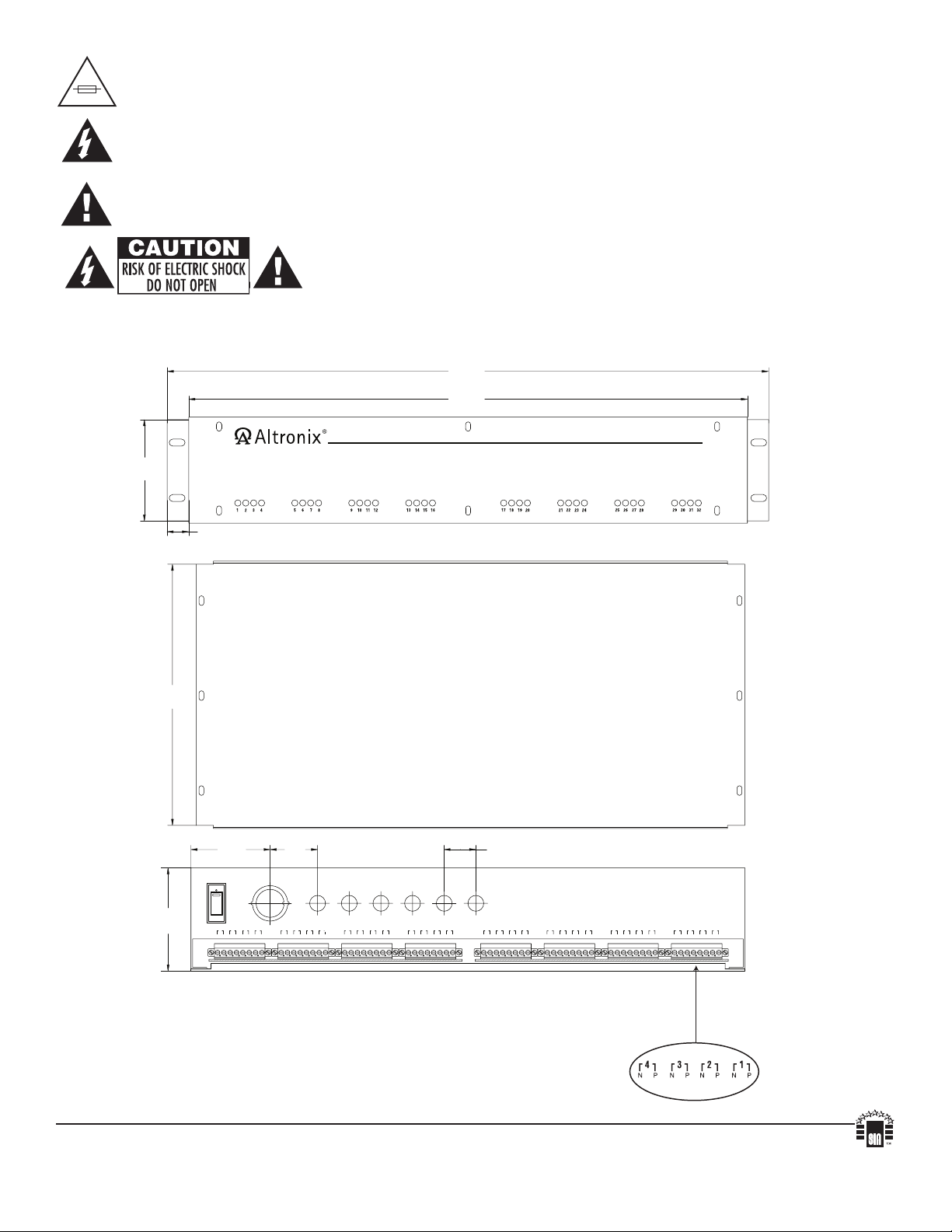
Rack Mechanical Drawing & Dimensions (H x W x D):
3.26” x 19.125” x 8.5” (83mm x 486mm x 216mm)
19.125”
(485.78mm)
17.5”
(444.5mm)
2.95”
(74.93mm)
(215.9mm)
(83mm)
8.5”
3.26”
0.65”
(16.51mm)
2.52”
(64mm)
RESET
OFF
32
Front View
Bottom View
1.5”
(38mm)
1.0”
(25.4mm)
Rear View
31
30
26
24272928
23
25
22
19
20
21
18
N P N PN PN P N P N PN PN P N P N PN PN P N P N PN PN P N PN PN PN PN P N PN PN PN P N PN PN PN P N PN PN P
16 15
17
12
14
11
13
8 7
10
9
4 3
6
5
2
1
Altronix is not responsible for any typographical errors.
Altronix Corp. 140 58th Street, Brooklyn, New York 11220 USA, 718-567-8181, fax: 718-567-9056
web site: www.altronix.com, e-mail: info@altronix.com. Lifetime Warranty, Made in U.S.A.
IIR2432ULSeries D11P
MEMBER
- 4 - R2432ULseries
 Loading...