

Page 1

PT2724 - Two (2) Channel
365 Day 24 Hr. Timer/Controller
Overview:
This unit is an extremely versatile two channel 365 Day 24 Hour Timer / Controller designed to
support a wide range of applications. Such applications include: Home and Building Automation,
Security, Access Control, Lighting Control, Etc.
The PT2724 is equipped with two independently controlled form “C” relay contact that provides
many latching and/or momentary operations during a program schedule of your choice. The
EE-Prom memory allows for programming of unit prior to/or during field installation. Events may
be set for single or multiple operations on a daily and/or weekly schedule. The block programming
feature enables repeating an event on any combination of consecutive days. PT2724 will
compensate for daylight savings time if desired. It automatically adjusts for leap year and individually selected holiday exceptions can be programmed to over-ride regularly scheduled events.
Specifications:
• 12 to 24 volts AC or DC operation.
• Stand-by current: 10mA (relay off) 50mA for each channel (relay on).
• Two (2) form “C” relay contacts are rated 10 amp @120VAC/28VDC.
• Tandem relay mode - allows both channels to activate simultaneously for all events.
• EE-Prom program memory protected against power loss.
• Accurate crystal controlled clock.
• Momentary and/or latching events.
• 50 individually programmed daily/weekly events per channel.
• Block programming capacity can accommodate a total of 350 events per week per channel.
• Ten (10) programmable Holiday dates per channel.
• “First man in” option.
• Alphanumeric LCD display simplifies programming.
• Standard or Daylight Savings Time settings.
• Automatic compensation for leap year.
• Built-in charger for 12VDC sealed lead acid or gel type batteries (Max charge current 100mA).
• Lithium battery backup maintains clock (optional) (Altronix part # LB2032).
• User friendly programming.
Board dimensions (approximate): 5.25”W x 3.5”L x 1.5”D
Installation Instructions:
1. Mount PT2724A in desired location.
Carefully Review:
Basic Operation (pg. 2)
Terminal Identification Table (pg. 2)
Push Button Layout and Description (pg. 3)
Programming Instructions (pgs. 4-7)
2. Connect 12 to 24 Volts AC or DC to terminals marked [+ DC -- / ~AC~].
(when using DC carefully observe polarity).
3. Connect 12VDC battery (optional) to terminals marked [+ BAT -- / 12VDC].
Page 2

4. Insert lithium battery (optional/not included. Order part LB2032) in battery
holder as shown in (Fig. 1, pg. 3) with the (+) positive side facing up.
5. Connect devices to be controlled to the dry relay outputs of either Channel A or Channel B.
Note: It is important when connecting DC powered electromechanical devices such as Mag
Locks, Electric Strikes, Bells, Relays, etc. to install a catch diode across the pos (+)
and neg (-) terminals of the device. Connect diode as close to the device as possible with the
banded side facing the pos (+) terminal. This will reduce the possibility of interference.
6. Program clock and desired event schedule (see Programming Instructions, pgs. 4-7).
Basic Operation:
PT2724 controls two independently operated dry form “C” relays. Relays can be programmed to:
turn on (latch), turn off (release latch) or pulse (momentary toggle) at a specified time and day
(this is referred to as an event). Events are programmed via the push buttons and LCD display.
Events may be programmed to occur on any day of the week at any time. In addition, events may
be programmed as a block event which repeat at a specific time on two (2) or more consecutive
days (i.e. MO-FR, SU-TH, etc) Multiple combinations of individual and block events may be
programmed. Holiday exceptions are individually selected by date and will over-ride all regularly
scheduled events.
The four (4) output relay modes consist of:
Relay OFF - De-energizes the relay until a relay ON event is detected
Relay ON - Energizes the relay until a relay OFF event is detected.
Disable - Used to cancel an existing programmed event.
Pulse - Momentarily energizes the relay for a selectable time period of 1 sec. to 15 secs.
Time is displayed in 24 hr. military format.
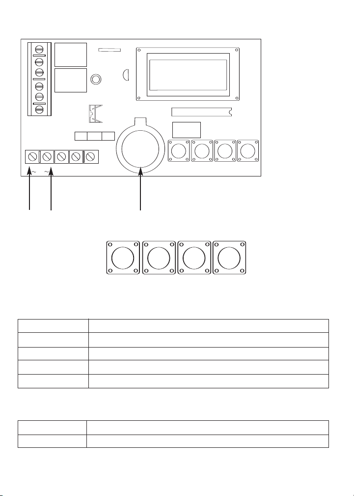
Terminal Identification Table:
Terminal Legend Function/Description
NO, C, NC, CH A Dry Contact outputs used to switch controlled devices. When these relays
NO, C, NC, CH B are energized (ON) the NC and C terminals are open and the NO and C
+ DC -- AC or DC Input 12 to 24 volt. When using DC carefully observe polarity.
~ AC ~
+ BAT -- 12VDC stand-by battery input (battery leads provided).
12VDC
FM When this terminal is connected to DC neg. (-) the “First Man in” feature
terminals are closed. When this relay is de-energized (Off) the NC and C
terminals are closed and the NO and C terminals are open.
is enabled. Both relays will remain in their present position until this
connection is terminated. At that time relays will resume normal
operation and latest scheduled events will occur.
- 2 -
Page 3
SET
ENTER
UP
DWN
FM
+
BAT ---
12VDC
+
DC ---
AC
SW2
SW3
NO C NC NO C NC
RELAY ON
SU 01:01
SET
ENTER
UP
DWN
Fig. 1
12-24 Volt
AC/DC input
3V Lithium Battery Socket
(Altronix part # LB2032)
Push Button Layout:
Push Button Description Table:
Push Button Function/Description
SET Scrolls thru program fields. Escapes out of existing programming.
ENTER Accepts programmed data.
UP Scrolls up through data selections.
DWN Scrolls down through data selections.
UP and DOWN keys can be used to select data entries. After scrolling to the correct entry,
depress ENTER to accept.
SW2 clip SW Selects tandem or individual relay operation.
SW3 slide SW Selects channel to be programmed.
- 3 -
Page 4

Programming Instructions:
The flashing cursor denotes location of data entry selection to be made. If an entry
was made in error or requires changing, depress SET to backspace, make the correct selection
and depress ENTER to accept data and advance the cursor.
A. Setting Clock/Calendar:
Upon initial power up CH ON
SU 01:01
will appear in display.
Depress SET until ENTER to
SET TIME
Depress ENTER 01/01/01
SU/01:01
Enter the current date, day of week and time (military) by depressing UP and DWN to
make the selection then depress ENTER to accept.
To program Daylight Savings Time (refer to Setting Block Events (weekly repeat) and
Daylight Savings Time - section C 2, page 6)
To change or program clock/calendar simply repeat the steps above.
B. Setting Events and Adding Events:
Select channel A or B by moving slide switch SW3 to appropriate position.
Note: Channel cannot be changed in the middle of programming events. To change channels
you must exit programming then change channel switch position then enter program mode again.
1. Setting Events
Depress SET until ENTER to
SET EVENT
Depress ENTER A01 OFF
Note: A01 indicates Channel A event 01.
When cursor appears you are able to scroll through events.
Depress ENTER until the flashing cursor appears under OFF (relay function) position in
display. Now select type of operation required, by scrolling using the UP and DWN push
buttons until either:
ON - Relay ON (latching mode).
OFF - Relay OFF (latching mode).
PL - Relay Pulse ( momentary).
appears in display and depressing ENTER will make selection.
When selecting the pulse mode PL01 will appear in the display. It is now necessary to assign
the length of time (duration of relay activation). The pulse can range in length from 1 second
minimum to 15 seconds maximum and is selected by using UP or DWN push buttons,
then depressing ENTER to accept.
>
SU 00:00
>
appears in display.
will appear in display.
appears in display.
will appear in display.
- 4 -
Page 5

Note: If pulse duration is not selected relay output defaults to 1 second.
Next select the individual day of the week by scrolling using UP and DWN push buttons
and depress ENTER to accept.
Next select the hour and minutes the event is to occur by scrolling using UP and DWN
push buttons and depress ENTER to accept.
You may continue to program events by repeating the previous steps or exit programming by
depressing SET.
Note: When programming additional events it is necessary to select the next consecutive
event number following the last event program to continue.
Note: When it is required to have the same event repeated on two (2) or more consecutive
days of the week, the event must be programmed as a block by selecting BK in the day field.
>
A01 OFF
BK 00:00
Note: To program the consecutive days of the week refer to Setting Block Event (weekly
repeat) and Daylight Savings Time - section C1 below.
2. Adding Events
Depress SET until ENTER to
SET EVENT
appears in display.
Depress ENTER A01 OFF
Depress ENTER , if the event is not programmed, the cursor will move to the OFF (relay function)
position. If the event is programmed the cursor will move to the position and the programmed
information of the event will be displayed. At this point depress the UP button to step up through
the programmed events. When an unprogrammed event is reached the cursor will move to the
OFF (relay function position). (At this point refer to setting events or setting holiday events.)
C. Setting Block Events (weekly repeat) and Daylight Savings Time:
Select channel A or B by moving slide switch SW3 to appropriate position.
Note: Channel cannot be changed in the middle of programming events. To change channels
you must exit programming then change channel switch position then enter program mode again.
Depress SET until ENTER to
Depress ENTER A=SA/SU
1. Block Event Programming
Flashing cursor will appear at the location of the first day of the week desired. Depress
UP and DWN to select day. Depress ENTER to confirm selection, then cursor will
appear at the location of the last day of the week desired. Depress UP and DWN to
select day. Depress ENTER to confirm selection.
>
SU 00:00
SET BK
TIME=DS
will appear in display.
>
appears in display.
will appear in display.
- 5 -
Page 6

1) Monday through Thursday depress MO followed by TH.
2) Wednesday through Sunday depress WE followed SU.
2. Daylight Savings Programming
The cursor will appear under DS (auto clock adjust daylight savings mode) in display. To
change mode depress UP or DWN once ST (clock does not adjust standard time mode)
will appear in display. Depress ENTER to accept correct selection.
Note: Select DS for areas that observe daylight savings or ST for areas that don’t
observe daylight savings.
D. Setting Holiday Events: (These events will occur on programmed Holiday Dates - see
Setting Holiday Dates below).
Select channel A or B by moving slide switch SW3 to appropriate position.
Note: Channel cannot be changed in the middle of programming events. To change channels
you must exit programming then change channel switch position then enter program mode again.
Find the first unprogrammed event (refer to Adding Events - section B2 page 6).
Depress ENTER until the flashing cursor appears under OFF (relay function) position in
display. Now select type of operation required, by scrolling using the UP and DWN push
buttons until either:
ON - Relay ON (latching mode).
OFF - Relay OFF (latching mode).
PL - Relay Pulse ( momentary).
appears in display and depressing ENTER will make selection.
When selecting the pulse mode PL01 will appear in the display. It is now necessary to assign
the length of time (duration of relay activation). The pulse can range in length from 1 second
minimum to 15 seconds maximum and is selected by using
then depressing ENTER to accept.
Note: If pulse duration is not selected relay output defaults to 1 second.
Next select HL (holiday) and time (military) by scrolling using UP and DWN push buttons
and depress ENTER to accept. You may continue to program events by repeating the previous
steps or exit programming by depressing SET.
UP or DWN push buttons,
E. Setting Holiday Dates:
Select channel A or B by moving slide switch SW3 to appropriate position.
Note: Channel cannot be changed in the middle of programming events. To change channels
you must exit programming then change channel switch position then enter program mode again.
It is now necessary to assign these holiday events specific calendar dates which they
are to occur.
Depress SET until ENTER to
SET HOL
Depress ENTER A01 HOL
>
SU 00:00
appears in display.
will appear in display.
- 6 -
Page 7

Enter the holiday date, day of week and year by depressing UP and DWN to
make the selection then depress ENTER to accept.
Note: Holiday events will override all regularly programmed events that occur on a
particular holiday date.
F. Delete/Disable Events or Edit Events:
Select channel A or B by moving slide switch SW3 to appropriate position.
Note: Channel cannot be changed in the middle of programming events. To change channels
you must exit programming then change channel switch position then enter program mode again.
Previously programmed regularly scheduled and/or holiday events may be deleted/
disabled without having to erase all events.
Depress SET until ENTER to
SET EVENT
Depress ENTER A01 ON
Now scroll using UP and DWN push buttons to the event you wish to delete, depress
ENTER to move flashing cursor under relay option then depress UP and DWN push
buttons until DIS is displayed, depress ENTER to confirm.
G. Delete All Events:
This will delete all previously programmed events.
Depress SET until ENTER to
Depress ENTER CLEAR
Depress
ENTER PRESS UP
Depressing UP push button will now clear all events previously programmed.
If you wish to escape from this selection depress any of the other push buttons:
SET, ENTER and DWN.
H. Tandem Relay Mode:
To operate in the Tandem Relay Mode, close switch SW2. This mode setting will allow
events programmed for Channel A and Channel B to operate both relays simultaneously
(1 DPDT relay output). This setting doubles the amount of programmable events.
>
TU 00:00
CLR MEM
MEMORY?
& ACCEPT
appears in display.
appears in display.
appears in display.
will appear in display.
will appear in display.
Note: When using the Tandem Relay mode, sequential ON/Off or OFF/ON events must be
programmed in the same channel. (If there is a Channel Program conflict, such as CH A is
set to ON and Channel B is set to OFF. The ON command will override the OFF and both
relays will remain ON.
- 7 -
Page 8

Customer Event Log
Event # Relay # Day/Block Holiday Dates Event Type
Altronix is not responsible for any typographical errors. Product specifications are subject to change without notice.
Altronix Corp.
140 58th Street, Brooklyn, New York 11220 USA, 718-567-8181, fax: 718-567-9056
web site: www.altronix.com, e-mail: info@altronix.com, Lifetime Warranty, Made in U.S.A.
IIPT2724 Rev. 110205 K02E
- 8 -
MEMBER
 Loading...