

Page 1

Maximal11E
- Power Supply 1:
12VDC @ 4 amp or 24VDC @ 3 amp.
- Power Supply 2:
12VDC @ 4 amp or 24VDC @ 3 amp.
Maximal33E
- Power Supply 1:
12VDC or 24VDC @ 6 amp.
- Power Supply 2:
12VDC or 24VDC @ 6 amp.
Maximal37E
- Power Supply 1:
12VDC or 24VDC @ 6 amp.
- Power Supply 2:
24VDC @ 10 amp.
Maximal75E
- Power Supply 1:
24VDC @ 10 amp.
- Power Supply 2:
12VDC @ 10 amp.
Maximal13E
- Power Supply 1:
12VDC @ 4 amp or 24VDC @ 3 amp.
- Power Supply 2:
12VDC or 24VDC @ 6 amp.
Maximal35E
- Power Supply 1:
12VDC or 24VDC @ 6 amp.
- Power Supply 2:
12VDC @ 10 amp.
Maximal55E
- Power Supply 1:
12VDC @ 10 amp.
- Power Supply 2:
12VDC @ 10 amp.
Maximal77E
- Power Supply 1:
24VDC @ 10 amp.
- Power Supply 2:
24VDC @ 10 amp.
Rev. ME080907
Series
Expandable Power Systems
Installation Guide
Models Include:
More than just power.
TM
Page 2

- 2 - Maximal Expandable Power Systems
Table of Contents:
MaximalE Overview ........................................................................................................ 3
MaximalE Series Configuration Chart ............................................................................ 3
MaximalE Features ....................................................................................................... 3-4
MaximalE Installation Instructions ................................................................................. 4
Maintenance ..................................................................................................................... 4
Power Supply Board Terminal Identification ................................................................. 5
Power Supply Board Stand-by Battery Specifications .................................................... 5
Power Supply Board LED Diagnostics ........................................................................... 6
Power Supply Board Output Voltage Settings ................................................................ 6
MaximalE Battery Hook-up Installation Instructions ..................................................... 7
NEC Power-Limited Wiring Requirements for Maximal11E.......................................... 8
NEC Power-Limited Wiring Requirements for Maximal13E.......................................... 9
NEC Power-Limited Wiring Requirements
for Maximal33E, Maximal35E and Maximal55E .......................................................... 10
NEC Power-Limited Wiring Requirements for Maximal37E and Maximal75E ........... 11
NEC Power-Limited Wiring Requirements for Maximal77E........................................ 12
Enclosure Dimensions .................................................................................................... 13
Page 3

Maximal Expandable Power Systems - 3 -
MaximalE Overview:
Maximal Expandable Power System provide system designers and installers with “maximum” power choices and the
highest levels of versatility. They provide 12VDC, 24VDC, or 12VDC and 24VDC simultaneously via two (2) single
output power supply/chargers. Includes AC fail, low battery and battery presence monitoring. Custom enclosure facilitates
up to four (4) 12VDC/12AH batteries. All interconnecting equipment must be UL Listed.
MaximalE Series Configuration Chart:
Altronix
Model Number
Output Voltage Options
Non Power-
Limeted Outputs
Class 2 Rated
Power-Limited
115VAC 60 Hz
Input (current)
Power Supply
Board
Agrncy
Listenings and
File Numbers
Power Supply 1 Power Supply 2
Maximal11E
AL400ULXB AL400ULXB
--- 2 4.5 amp 3.5A/250V
California State Fire
Marshal Approved
UL File # BP6714
UL 294
UL Listed for
Access Control
System Units.
General Signaling
Equipment
Evaluated to
CSA Standard
C22.2 No.205-M1983
12VDC @ 4 amp 12VDC @ 4 amp
12VDC @ 4 amp 24VDC @ 3 amp
24VDC @ 3 amp 24VDC @ 3 amp
Maximal13E
AL400ULXB AL600ULXB
1 1 5 amp 3.5A/250V
12VDC @ 4 amp 12VDC @ 6 amp
12VDC @ 4 amp 24VDC @ 6 amp
24VDC @ 3 amp 12VDC @ 6 amp
24VDC @ 3 amp 24VDC @ 6 amp
Maximal33E
AL600ULXB AL600ULXB
2 --- 7 amp 3.5A/250V
12VDC @ 6 amp 12VDC @ 6 amp
12VDC @ 6 amp 24VDC @ 6 amp
24VDC @ 6 amp 24VDC @ 6 amp
Maximal35E
AL600ULXB AL1012ULXB
2 --- 6 amp 3.5A/250V
12VDC @ 6 amp 12VDC @ 10 amp
24VDC @ 6 amp 12VDC @ 10 amp
Maximal37E
AL600ULXB AL1024ULXB
2 --- 10 amp
3.5A/250V
(AL600ULXB)
10A/250V
(AL1024ULXB)
12VDC @ 6 amp 24VDC @ 10 amp
24VDC @ 6 amp 24VDC @ 10 amp
Maximal55E
AL1012ULXB AL1012ULXB
2 --- 6 amp 3.5A/250V
12VDC @ 10 amp 12VDC @ 10 amp
Maximal75E
AL1012ULXB AL1024ULXB
2 --- 10 amp
3.5A/250V
(AL1012ULXB)
10A/250V
(AL1024ULXB)
12VDC @ 10 amp 24VDC @ 10 amp
Maximal77E
AL1024ULXB AL1024ULXB
2
--- 12.5 amp 10A/250V
24VDC @ 10 amp 24VDC @ 10 amp
MaximalE Features:
• Filteredandelectronicallyregulatedoutputs
(built-in power supply).
• Built-inchargerforsealedleadacidorgeltypebatteries.
• AL400ULXB,AL600ULXBandAL1012ULXB
(Power Supply Board) maximum charge current .7 amp.
AL1024ULXB (Power Supply Board) maximum charge
current 3.6 amp.
• Automaticswitchovertostand-bybatterywhenACfails.
• Zerovoltagedropwhenunitswitchesoverto
battery backup (AC failure condition).
• Lowbatteryandbatterypresencesupervision
(form “C” contact).
Page 4

- 4 - Maximal Expandable Power Systems
MaximalE Features (cont’d):
• Shortcircuitandthermaloverloadprotection
with auto reset.
• ACinputandDCoutputLEDindicators.
• ACfailsupervision(form“C”contact).
• Enclosureaccommodatesuptofour(4)
12VDC/12AH batteries.
Enclosure dimensions: 26”H x 19”W x 6.25”D
MaximalE Installation Instructions:
Wiring methods shall be in accordance with the National Electrical Code/NFPA 70/ANSI, and with all local codes and
authorities having jurisdiction. Product is intended for indoor use only.
Power Supply Board Terminal Identification (pg. 5)
Power Supply Stand-by Battery Specifications (pg. 5)
Power Supply Board LED Diagnostics (pg. 6)
Power Supply Board Output Voltage Settings (pg. 6)
1. Mount unit in desired location. Mark and predrill holes in the wall to line up with the top three keyholes in the
enclosure. Install three upper fasteners and screws in the wall with the screw heads protruding. Place the enclosure’s
upper keyholes over the three upper screws, level and secure. Mark the position of the lower three holes. Remove the
enclosure. Drill the lower holes and install the three fasteners. Place the enclosure’s upper keyholes over the three
upper screws. Install the three lower screws and make sure to tighten all screws (Enclosure Dimensions, pg. 13).
2. The power supply is pre-wired to the ground (chassis). Connect main incoming ground to the provided green
grounding conductor lead. Connect unswitched AC power (115VAC 60Hz) to terminals marked [L, N] on both
power supply boards. Use 14 AWG or larger for all power connections. (Fig. 2, pg. 7).
Keep power limited wiring separate from non-power limited wiring. Minimum .25” spacing must be provided.
3. Select desired DC output voltage by setting SW1 to the appropriate position, (Maximal11E, Maximal13E,
Maximal33E, Maximal35E and Maximal37E) (Fig. 1, pg. 6). Maximal55E power supplies are factory set at 12VDC.
Maximal77E power supplies are factory set at 24VDC. Maximal75E power supplies are factory set at 12VDC and
24VDC, (Power Supply Board Stand-by Battery Specifications, pg. 5).
4. Measure the output voltage of the unit before connecting any devices to ensure proper operation.
Improper or high voltage will damage these devices.
5. Connect devices to be powered to terminals marked [+ DC -] (Fig. 2, pg. 7).
6. For Access Control applications, batteries are optional. When batteries are not used a loss of AC will result in the
loss of output voltage. When the use of stand-by batteries is desired, they must be lead acid or gel type.
Connect battery to terminals marked [+ BAT -- ] (Figs. 2-7, pgs. 7-12).
Use two (2) 12VDC batteries connected in series for 24VDC operation (battery leads included).
7. Battery and AC Supervision outputs: It is required to connect supervisory trouble reporting devices to outputs marked
[AC Fail, BAT FAIL] supervisory relay outputs marked [NC, C, NO] to appropriate visual
notification devices. Use 22 AWG to 18 AWG for AC Fail & Low/No Battery reporting (Fig. 2a, pgs. 7).
8. Mount UL Listed tamper switch (Not Included) (Sentrol model 3012 or equivalent) at the top of the enclosure.
Slide the tamper switch bracket onto the edge of the enclosure approximately 2” from the right side (Fig. 2b, pg. 7).
Connect tamper switch wiring to the Access Control Panel input or the appropriate UL Listed reporting device.
To activate alarm signal open the door of the enclosure.
9. Please insure that the cover is secured with the provided key lock.
Maintenance:
Unit should be tested at least once a year for the proper operation as follows:
Output Voltage Test: Under normal load conditions, the DC output voltage should be checked for proper voltage level
(Power Supply Stand-by Battery Specifications, pg. 5).
Battery Test: Under normal load conditions check that the battery is fully charged, check specified voltage at
the battery terminals and at the board terminals marked [+ BAT -- ] to insure that there is no break in the battery
connection wires.
Note: AL400ULXB, AL600ULXB and AL1012ULXB (Power Supply Board) maximum charge current is .7 amp.
AL1024ULXB (Power Supply Board) maximum charge current is 3.6 amp.
Expected battery life is 5 years, however it is recommended to change batteries within 4 years or less if necessary.
Page 5
Maximal Expandable Power Systems - 5 -
Power Supply Board Terminal Identification:
Terminal
Legend
Function/Description
L. G, N Connect 115VAC 60Hz to these terminals: L to hot, N to neutral, G to ground.
- DC + Refer to Maximal Series Configuration Chart, pg. 3.
AC FAIL
NC, C, NO
Indicates loss of AC power. To meet with UL requirements it is mandatory to connect visual notification
devices, connecting audible notification devices is optional. Relay normally energized when AC power is
present. Contact rating 1 amp @ 28VDC. AC or brownout fail is reported within 1 minute of event.
BAT FAIL
NC, C, NO
Indicates low battery condition, e.g. connect to alarm panel. Relay normally energized when DC
power is present. Contact rating 1 amp @ 28VDC. A removed battery is reported within 5 minutes.
Battery reconnection is reported within 1 minute.
Low battery threshold:
12VDC output threshold set @ approximately 10.5VDC.
24VDC output threshold set @ approximately 21VDC.
+ BAT -
Stand-by battery connections. AL400ULXB, AL600ULXB and AL1012ULXB (Power Supply Board)
maximum charge current is .7 amp. AL1024ULXB (Power Supply Board) maximum charge current is
3.6 amp.
Power Supply Board Stand-by Battery Specifications
Altronix
Model
Power Supply Board Battery
20 min. of
Backup
4 hr. of
Backup
24 hr. of
Backup
60 hr. of
Backup
Maximal11E
Maximal13E
AL400ULXB
(Refer to Fig. 1a, 1b on
pg. 6 for Switch [SW1]
location and position)
12VDC/40AH*
N/A 4 amp 1 amp 300mA
24VDC/12AH
N/A 200mA N/A N/A
24VDC/40AH*
N/A 3 amp 1 amp 300mA
Maximal13E
Maximal33E
Maximal35E
Maximal37E
AL600ULXB
(Refer to Fig. 1b, 1c on
pg. 6 for Switch [SW1]
location and position)
12VDC/40AH*
N/A 6 amp 1 amp 300mA
24VDC/12AH
N/A 200mA N/A N/A
24VDC/40AH*
N/A 6 amp 1 amp 300mA
Maximal35E
Maximal55E
Maximal75E
AL1012ULXB
(Factory set at 12VDC)
12VDC/12AH 10 amp
Battery capacity
for emergency
standby at least
20 min
N/A N/A
Maximal37E
Maximal75E
Maximal77E
AL1024ULXB
(Factory set at 24VDC)
24VDC/12AH
8 amp 1.5 amp 200mA 100mA
24VDC/65AH* N/A
8 amp 1.5 amp 500mA
* Note: Additional battery enclosure required (Figs. 3-5, pgs, 8-10).
Page 6

- 6 - Maximal Expandable Power Systems
NO NC C NO
+ BAT ---
24V - OPEN
12V - CLOSED
AC FAIL
RL3
SW1
AC Delay
BAT FAIL
NC C NO NC C NO
+ BAT ---
DC
AC FAIL
AC
24V - OPEN
12V - CLOSED
SW1
Fig. 1a
AL400ULXB Power Supply Board
Fig. 1c
AL600ULXB Power Supply Board
Fig. 1b
OPEN SWITCH
CLOSED SWITCH
Switch Detail
Power Supply Board LED Diagnostics:
LED
Power Supply Status
Red (DC)
Green (AC)
ON
ON
Normal operating condition.
ON
OFF
Loss of AC, Stand-by battery supplying power
OFF
ON
No DC output. Short circuit or thermal overload condition.
OFF
OFF
No DC output. Loss of AC. Discharged battery
Power Supply Board Output Voltage Settings:
Fig. 1Fig. 1
Page 7

Maximal Expandable Power Systems - 7 -
Ground Lug
--- DC +
BAT FAIL
NO C NC NO C NC
+ BAT ---
AC FAIL
Power Supply Board
L G N
--- DC +
BAT FAIL
NO C NC NO C NC
+ BAT ---
AC FAIL
Power Supply Board
L G N
Ground Lug
Line
Neutral
GroundLine
Neutral
*12VDC operation: For 12VDC operation
only a single battery is needed.
Connect red battery lead
to terminal marked
[+ BAT] and to the
[positive (+)] terminal
of the battery. Connect
black battery lead to
terminal marked [BAT -]
and to the [negative (-)]
terminal of the battery.
Tamper Switch
12VDC Rechargeable
Battery**
(Optional)
12VDC Rechargeable
Battery*
(Optional)
12VDC Rechargeable
Battery**
(Optional)
115VAC
Input
60 Hz.
Ground
+ DC ---
NO C NC NO C NC
+ BAT ---
AC FAIL
**24VDC operation: Connect two (2) 12VDC
batteries in series
Fig. 2
Fig. 2b
Edge of
Enclosure
to Access Control Panel
or U.L. Listed
Reporting Device
Enclosure
Sentrol
model # 3012
Tamper Switch
or equiva lent
(Not Included)
Power Supply Board Terminal
Layout for: AL400ULXB,
AL600ULXB and AL1012ULXB
Fig. 2a
Page 8
- 8 - Maximal Expandable Power Systems
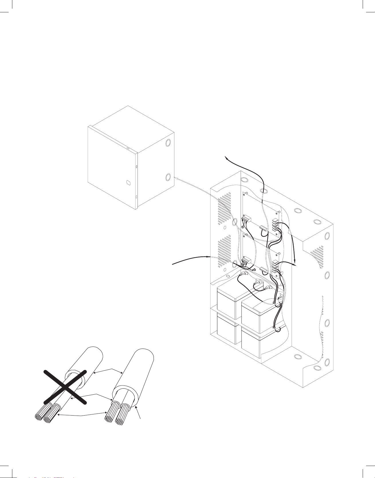
NEC Power-Limited Wiring Requirements for Maximal11E:
Power-limited and non power-limited circuit wiring must remain separated in the cabinet. All power-limited circuit wiring
must remain at least 0.25” away from any non power-limited circuit wiring. Furthermore, all power-limited circuit wiring
and non power-limited circuit wiring must enter and exit the cabinet through different conduits. One such example of this
is shown below. Your specific application may require different conduit knockouts to be used. Any conduit knockouts
may be used. For power- limited applications, use of conduit is optional.
All field wiring connections must be made employing suitable gauge CM or FPL jacketed wire (or equivalent substitute).
Note: Refer to wire handling drawing below for the proper way to install the CM or FPL jacketed wire, (Fig, 3a).
Fig. 3
External
Jacketed
Shield
Incorrect Wire
Handling
Correct Wire
Handling
Pull back external
jacketed shield
approximately 1/2”.
Wi re
Insulation
Solid
Copper
Conductors
Fig. 3a
Supervisory
Connections
(power-limited)
115VAC Input
60Hz
(non power-limited)
Optional Battery
Enclosure
(non power-limited)
DC Output
Wiring
(powerlimited)
Battery
Connections
(non power-limited)
Page 9

Maximal Expandable Power Systems - 9 -
NEC Power-Limited Wiring Requirements for Maximal13E:
Power-limited and non power-limited circuit wiring must remain separated in the cabinet. All power-limited circuit wiring
must remain at least 0.25” away from any non power-limited circuit wiring. Furthermore, all power-limited circuit wiring
and non power-limited circuit wiring must enter and exit the cabinet through different conduits. One such example of this
is shown below. Your specific application may require different conduit knockouts to be used. Any conduit knockouts
may be used. For power- limited applications, use of conduit is optional.
All field wiring connections must be made employing suitable gauge CM or FPL jacketed wire (or equivalent substitute).
Note: Refer to wire handling drawing below for the proper way to install the CM or FPL jacketed wire, (Fig, 4a).
Fig. 4
External
Jacketed
Shield
Incorrect Wire
Handling
Correct Wire
Handling
Pull back external
jacketed shield
approximately 1/2”.
Wi re
Insulation
Solid
Copper
Conductors
Fig. 4a
Supervisory
Connections
(power-limited)
115VAC Input
60Hz
(non power-limited)
Optional Battery
Enclosure
(non power-limited)
DC Output
Wiring
(non
power-
limited)
Battery
Connections
(non power-limited)
DC Output
Wiring
(powerlimited)
Page 10

- 10 - Maximal Expandable Power Systems
NEC Power-Limited Wiring Requirements for Maximal33E, Maximal35E and
Maximal55E:
Power-limited and non power-limited circuit wiring must remain separated in the cabinet. All power-limited circuit wiring
must remain at least 0.25” away from any non power-limited circuit wiring. Furthermore, all power-limited circuit wiring
and non power-limited circuit wiring must enter and exit the cabinet through different conduits. One such example of this
is shown below. Your specific application may require different conduit knockouts to be used. Any conduit knockouts
may be used. For power- limited applications, use of conduit is optional.
All field wiring connections must be made employing suitable gauge CM or FPL jacketed wire (or equivalent substitute).
Note: Refer to wire handling drawing below for the proper way to install the CM or FPL jacketed wire, (Fig, 5a).
Fig. 5
External
Jacketed
Shield
Incorrect Wire
Handling
Correct Wire
Handling
Pull back external
jacketed shield
approximately 1/2”.
Wi re
Insulation
Solid
Copper
Conductors
Fig. 5a
Supervisory
Connections
(power-limited)
115VAC Input
60Hz
(non power-limited)
Optional Battery
Enclosure
(non power-limited)
DC Output
Wiring
(non
power-
limited)
Battery
Connections
(non power-limited)
Page 11

Maximal Expandable Power Systems - 11 -
NEC Power-Limited Wiring Requirements for Maximal37E and Maximal75E:
Power-limited and non power- limited circuit wiring must remain separated in the cabinet. All power-limited circuit wiring
must remain at least 0.25” away from any non power-limited circuit wiring. Furthermore, all power-limited circuit wiring
and non power-limited circuit wiring must enter and exit the cabinet through different conduits. One such example of this
is shown below. Your specific application may require different conduit knockouts to be used. Any conduit knockouts
may be used. For power-limited applications, use of conduit is optional.
All field wiring connections must be made employing suitable gauge CM or FPL jacketed wire (or equivalent substitute).
Note: Refer to wire handling drawing below for the proper way to install the CM or FPL jacketed wire, (Fig, 6a).
Fig. 6
External
Jacketed
Shield
Incorrect Wire
Handling
Correct Wire
Handling
Pull back external
jacketed shield
approximately 1/2”.
Wi re
Insulation
Solid
Copper
Conductors
Fig. 6a
Supervisory
Connections
(power-limited)
115VAC Input
60Hz
(non power-limited)
Optional Battery
Enclosure
(non power-limited)
DC Output
Wiring
(non
power-
limited)
Battery
Connections
(non power-limited)
Page 12

- 12 - Maximal Expandable Power Systems
NEC Power-Limited Wiring Requirements for Maximal77E:
Power-limited and non power-limited circuit wiring must remain separated in the cabinet. All power-limited circuit wiring
must remain at least 0.25” away from any non power-limited circuit wiring. Furthermore, all power-limited circuit wiring
and non power-limited circuit wiring must enter and exit the cabinet through different conduits. One such example of this
is shown below. Your specific application may require different conduit knockouts to be used. Any conduit knockouts
may be used. For power-limited applications, use of conduit is optional.
All field wiring connections must be made employing suitable gauge CM or FPL jacketed wire (or equivalent substitute).
Note: Refer to wire handling drawing below for the proper way to install the CM or FPL jacketed wire, (Fig, 7a).
Fig. 7
Supervisory
Connections
(power-limited)
115VAC Input
60Hz
(non power-limited)
Optional Battery
Enclosure
(non power-limited)
DC Output
Wiring
(non
power-
limited)
External
Jacketed
Shield
Incorrect Wire
Handling
Correct Wire
Handling
Pull back external
jacketed shield
approximately 1/2”.
Wi re
Insulation
Solid
Copper
Conductors
Fig. 7a
Battery
Connections
(non power-limited)
Page 13

Maximal Expandable Power Systems - 13 -
Enclosure Dimensions:
26”H x 19”W x 6.25”D
Page 14

- 14 - Maximal Expandable Power Systems
Notes:
Page 15

Maximal Expandable Power Systems - 15 -
Notes:
Page 16

- 16 - Maximal Expandable Power Systems
Altronix is not responsible for any typographical errors.
140 58th Street, Brooklyn, New York 11220 USA, 718-567-8181, fax: 718-567-9056
web site: www.altronix.com, e-mail: info@altronix.com, Lifetime Warranty, Made in U.S.A.
IIMaximalE Series L21J
Notes:
MEMBER
 Loading...