

Page 1

Series
Access Power Controllers
Installation Guide
Models Include:
Maximal11D
- Power Supply 1:
12VDC @ 3.5 amp or 24VDC @ 2.7 amp.
- Power Supply 2:
12VDC @ 3.5 amp or 24VDC @ 2.7 amp.
- Sixteen (16) PTC protected
Class 2 Rated power-limited outputs.
Maximal33D
- Power Supply 1:
12VDC @ 5.5 amp or 24VDC @ 5.7 amp.
- Power Supply 2:
12VDC @ 5.5 amp or 24VDC @ 5.7 amp.
- Sixteen (16) PTC protected
Class 2 Rated power-limited outputs.
Maximal55D
- Power Supply 1: 12VDC @ 9.5 amp.
- Power Supply 2: 12VDC @ 9.5 amp.
- Sixteen (16) PTC protected
Class 2 Rated power-limited outputs.
Maximal77D
- Power Supply 1: 24VDC @ 9.7 amp.
- Power Supply 2: 24VDC @ 9.7 amp.
- Sixteen (16) PTC protected
Class 2 Rated power-limited outputs.
Maximal75D
- Power Supply 1: 12VDC @ 9.5 amp.
- Power Supply 2: 24VDC @ 9.7 amp.
- Sixteen (16) PTC protected
Class 2 Rated power-limited outputs.
Altronix Corp.
140 58th St. Brooklyn, NY
Rev. DCB102512
More than just power.
TM
Page 2

Table of Contents:
MaximalD Series Overview ............................................................................................. 3
MaximalD Series Configuration Chart ............................................................................. 3
MaximalD Series Features ............................................................................................ 3-4
MaximalD Installation Instructions ............................................................................... 4-5
Maintenance ...................................................................................................................... 6
Power Supply Board LED Diagnostics ............................................................................ 6
Access Power Controller LED Diagnostics ..................................................................... 6
Power Supply Board Terminal Identification .................................................................. 7
Access Power Controller Terminal Identification ............................................................ 7
Power Supply Board Stand-by Battery Specifications ...................................................... 8
Power Supply Board Output Voltage Settings ................................................................. 9
Access Power Controller Typical Application Diagram ................................................... 9
Maximal11D, Maximal33D and Maximal55D Battery Hookup
and Tamper Switch Installation ...................................................................................... 10
Maximal77D Battery Hookup and Tamper Switch Installation .................................... 11
Maximal75D Battery Hookup and Tamper Switch Installation .................................... 12
NEC Power-Limited Wiring Requirements for Maximal11D ........................................ 13
NEC Power-Limited Wiring Requirements for Maximal33D and Maximal55D ........... 14
NEC Power-Limited Wiring Requirements for Maximal77D ....................................... 15
NEC Power-Limited Wiring Requirements for Maximal75D ....................................... 16
FACP/Optional Power Supply Hook-up Diagrams........................................................ 17
Enclosure Dimensions .................................................................................................... 18
- 2 - Maximal11D/Maximal33D/Maximal55D/Maximal77D/Maximal75D Access Power Controllers (PTC)
Page 3
MaximalD Series Overview:
Maximal Access Power/Controllers distribute and switch power to access control systems and accessories. They convert a 115VAC 60Hz input into sixteen (16) independently controlled 12VDC or 24VDC Class 2 Rated PTC protected
power-limited outputs. These Fail-Safe/Fail-Secure power outputs may be converted to dry form “C” contacts. The outputs
are activated by an open collector sink or normally open (NO) dry trigger input from an Access Control System, Keypad,
Push Button, REX PIR, etc. Units will route power to a variety of access control hardware devices including: Mag Locks,
Electric Strikes, Magnetic Door Holders, etc. The FACP Interface enables Emergency Egress, Alarm Monitoring, or may
be used to trigger other auxiliary devices. The fire alarm disconnect feature is individually selectable for any or all of the
sixteen (16) outputs. All interconnecting equipment must be UL Listed.
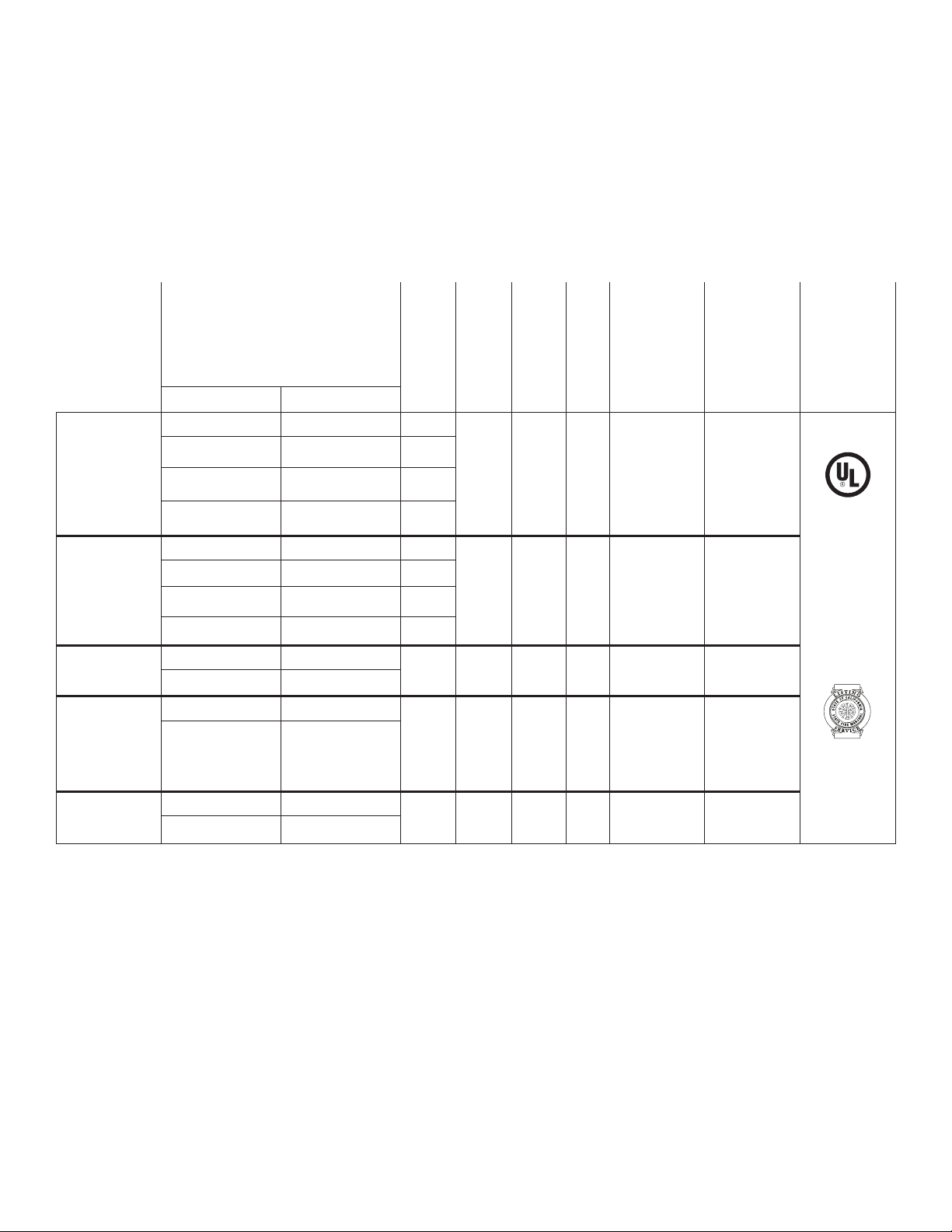
MaximalD Series Configuration Chart:
Altronix
Model
Number
Maximal11D
Maximal33D
Maximal55D
Maximal75D
Maximal77D
Output Voltage Options
Power Supply 1 Power Supply 2
Total Output
Current
AL400ULXB AL400ULXB ------
12VDC @ 3.5A 12VDC @ 3.5A 7A
12VDC @ 2.7A 24VDC @ 2.7A 5.4A
24VDC @ 3.5A 24VDC @ 2.7A 6.2A
AL600ULXB AL600ULXB ------
12VDC @ 5.5A 12VDC @ 5.5A 11A
12VDC @ 5.7A 24VDC @ 5.7A 11.4A
24VDC @ 5.5A 24VDC @ 5.7A 11.2A
AL1012ULXB AL1012ULXB
12VDC @ 9.5A 12VDC @ 9.5A
19 2.5A 16 5.2A 5A/250V 15A/32V
AL1012ULXB AL1024ULXB
12VDC @ 9.5A 24VDC @ 9.5A
19 2.5A 16 7.0A
AL1024ULXB AL1024ULXB
24VDC @ 9.7A 24VDC @ 9.7A
19.4
(16 outputs)
Current per
ACM8CB
Output
Class 2 Rated PTC
Protected Power
Limited Outputs
115VAC 60 Hz
Input (current)
Power Supply
Board Input
Fuse Rating
Power Supply
2.5A 16 7A 5A/250V 15A/32V
2.5A 16 7A 5A/250V ------
5A/250V
(AL1012ULXB)
and
(AL1024ULXB)
15A/32V
(AL1012ULXB)
(AL1024ULXB)
2.5A 16 8.8A 5A/250V 15A/32V
Board Output
Fuse Rating
and
Agency Listings
UL File #
BP6714
UL 294
UL Listed
California
Fire Marshal
Approved
and File Numbers
for
Access
Control
System
Units.
Altronix Corp.
140 58th St. Brooklyn, NY
State
MaximalD Series Features:
• Sixteen(16)independentlytriggercontrolledoutputs.
Output options:
a) Sixteen (16) Fail-Safe filtered and electronically regulated power outputs.
b) Sixteen (16) Fail-Secure filtered and electronically regulated power outputs.
c) Sixteen (16) form “C” relay outputs (rated @ 5 amp/28VDC or VAC).
d) Any combination of the above.
• Sixteen(16)AccessControlSystemtriggerinputs.
Input trigger options:
a) Sixteen (16) normally open (NO) dry trigger inputs.
b) Sixteen (16) open collector inputs.
c) Any combination of the above.
• Sixteen(16)unswitchedfilteredandelectronicallyregulatedaux.poweroutputs(outputsarerated@2amp).
• ACM8CBmaximumcurrentis2ampperoutput.
Maximal11D/Maximal33D/Maximal55D/Maximal77D/Maximal75D Access Power Controllers (PTC) - 3 -
Page 4

• RedLEDsonACM8CBboardindicateindividualoutputsaretriggered(relaysenergized).
• FireAlarmdisconnect(latchingornon-latching)isindividuallyselectableforanyorallofthesixteen(16)outputs.
Fire Alarm disconnect input trigger options:
a) Normally open (NO) or normally closed (NC) dry trigger input.
b) Polarity reversal input from FACP signaling circuit.
• GreenLEDonACM8CBboardindicatesFACPdisconnectistriggered.
• FACP output relay indicates that FACP input is triggered (form “C” contact rated @ 1 amp/28VDC not evaluated by UL).
• Powersupplyinputoptions:
a) Factory installed power supplies provide common power for both ACM8CB boards and all connected
access control devices.
b) An optional UL Listed power-limited external access control power supply may be connected to isolate
the ACM8CB boards from the access control devices (only applicable on Maximal11D).
• ACM8CBboardmainfusesarerated@10amp.OutputPTCsarerated@2amp.
• Built-inchargerforsealedleadacidorgeltypebatteries.
- Maximum charge current is 0.7 amp for AL400ULXB, AL600ULXB and AL1012ULXB power supply boards.
- Maximum charge current is 3.6 amp for AL1024ULXB power supply board.
• Automaticswitchovertostand-bybatterywhenACfails.
• Zerovoltagedropwhenunitswitchesovertobatterybackup(ACfailurecondition).
• Shortcircuitandthermaloverloadprotectionwithautoreset.
• GreenACinputandredDCoutputLEDindicatorsonpowersupplyboard(s).
• ACfailsupervision(form“C”contactrated@1amp/28VDC).
• Batteryfailandbatterypresencesupervision(form“C”contactrated@1amp/28VDC).
• Enclosureaccommodatesuptofour(4)12VDC/12AHbatteries.
Enclosure dimensions: 26” (660.4mm) x 19” (482.6mm) x 6.25” (158.75mm)
MaximalD Installation Instructions:
Wiring methods shall be in accordance with the National Electrical Code/NFPA 70/ANSI, and with all local codes and
authorities having jurisdiction. Product is intended for indoor use only.
Power Supply Board LED Diagnostics (pg. 6)
Access Power Controller LED Diagnostics (pg. 6)
Power Supply Board Terminal Identification (pg. 6)
Access Power Controller Terminal Identification (pg. 7)
Power Supply Board Stand-by Battery Specifications (pg. 7)
Power Supply Board Output Voltage Settings (pg. 8)
Access Power Controller Typical Application Diagram (pg. 8)
FACP/Optional Power Supply Hook-up Diagrams (pg. 16)
1. Mount unit in desired location. Mark and predrill holes in the wall to line up with the top three keyholes in the
enclosure. Install three upper fasteners and screws in the wall with the screw heads protruding. Place the enclosure’s
upper keyholes over the three upper screws, level and secure. Mark the position of the lower three holes.
Remove the enclosure. Drill the lower holes and install the three fasteners. Place the enclosure’s upper keyholes
over the three upper screws. Install the three lower screws and make sure to tighten all screws
Enclosure Dimensions, pg.18).
2. The power supply is pre-wired to the ground (chassis). Connect main incoming ground to the provided green
grounding conductor lead. Connect unswitched AC power (115VAC 60Hz) to terminals marked [L, N] on both
powersupplyboards.Use14AWGorlargerforallpowerconnections.
Keep power-limited wiring separate from non power-limited wiring. Minimum .25” spacing must be provided
(Figs. 6-9, pgs. 13-16).
3. Select desired DC output voltage by setting SW1 to the appropriate position on the power supply board
(Maximal11D and Maximal33D), (Fig. 1, pg. 9). Maximal55D power supply is factory set at 12VDC.
Maximal77D power supply is factory set at 24VDC. Maximal75D consists of one (1) power supply board that is
factory set at 12VDC, and one (1) power supply board that is factory set at 24VDC.
4. Measure the output voltage of the unit before connecting any devices to ensure proper operation.
Improper or high voltage will damage these devices.
5. Output options (Fig. 2, pg. 9):
The unit will provide either sixteen (16) switched power outputs, sixteen (16) dry form “C” outputs, or any
combination of both switched power and form “C” outputs.
- 4 - Maximal11D/Maximal33D/Maximal55D/Maximal77D/Maximal75D Access Power Controllers (PTC)
Page 5

(a) Fail-Safe Switched Power outputs:
For Fail-Safe operation connect the positive (+) input of the access control devices to terminal marked [NC].
Connect the negative (-) input of the access control devices to terminal marked [COM].
(b) Fail-Secure Switched Power outputs:
For Fail-Secure operation connect the positive (+) input of the access control devices to terminal marked [NO].
Connect the negative (-) input of the access control devices to terminal marked [COM].
(c) Form “C” outputs:
When form “C” outputs are desired the corresponding output PTCs (1-8) of each ACM8CB board must be removed.
6. Auxiliary Power outputs (unswitched):
Connect access control devices that require constant power to terminals marked [C] positive (+) and [COM] negative (-).
7. Input trigger options (Fig. 2, pg. 9):
(a) Normally Open [NO] input trigger:
Inputs 1-8 are activated by normally open or open collector sink inputs.
Connectaccesscontrolpaneloutputs,keypads,pushbuttons,REXPIRs,etc.toterminalsmarked[IN]and[GND].
(b) Open Collector Sink inputs:
Connect the access control panel open collector sink positive (+) to terminals marked [IN] and the negative (-) to
terminalsmarked[GND].
8. Fire Alarm Interface options (Figs. 10-15, pg. 17):
A normally closed [NC] or normally open [NO] input trigger from a fire alarm control panel or a polarity reversal
input from an FACP signaling circuit will affect selected outputs. To enable FACP Disconnect for an output
open the corresponding switch(es) [SW1-SW8] on each ACM8CB board. To disable FACP disconnect for an
output close the corresponding switch(es) [SW1-SW8] on each ACM8CB board.
(a) Normally Open [NO] input:
For non-latching hook-up refer to (Fig. 12, pg. 17). For latching hook-up refer to (Fig. 13, pg. 17).
(b) Normally Closed [NC] input:
For non-latching hook-up refer to (Fig. 14, pg. 17). For latching hook-up refer to (Fig. 15, pg. 17).
(c) FACP Signaling Circuit input trigger:
Connect the positive (+) and negative (-) from the FACP signaling circuit output to the terminals marked [+ INP -].
Connect the FACP EOL to the terminals marked [+ RET -] (polarity is referenced in an alarm condition).
Jumper J3 must be cut (Fig. 11, pg. 17).
9. FACP Dry form “C” output (Fig. 2a, pg. 9):
FACP form “C” contacts can be use to trigger reporting or signaling devices. These contact switch
upon a fire alarm input trigger to the ACM8CB boards.
10. Stand-by Battery Connections (Figs. 3-5, pgs. 10-12):
For Access Control applications batteries are optional. If batteries are not used a loss of AC will result in the loss of
output voltage. Batteries must be lead acid or gel type. Connect one (1) 12VDC battery to the terminals marked
[+ BAT -] for 12VDC operation (Figs. 3, 5, pgs. 10, 12). Use two (2) 12VDC batteries wired in series for
24VDC operation (Figs. 3-5, pgs. 10-12).
11. Battery and AC Supervision outputs (Figs. 3-5, pgs. 10-12):
It is required to connect supervisory trouble reporting devices to outputs marked [AC Fail, BAT FAIL] supervisory
relayoutputsmarked[NC,C,NO]toappropriatevisualnotificationdevices.Use22AWGto18AWGfor
AC Fail & Low/No Battery reporting.
12. Installation of tamper switch (Not Included) (Figs. 3a, 4a, 5a, pgs. 10-12):
Mount UL Listed tamper switch (Sentrol model 3012 or equivalent) at the top of the enclosure. Slide the tamper
switch bracket onto the edge of the enclosure approximately 2” from the right side. Connect tamper switch wiring to
the Access Control Panel input or the appropriate UL Listed reporting device. To activate alarm signal open the door
of the enclosure.
13. Multiple power supply inputs (Fig. 2, pg. 9):
When using an additional UL Listed external power supply, jumpers J1 and J2 located on corresponding
ACM8CB boards must be cut (Fig. 2b, pg. 9 & Fig. 10, pg. 17). Connect external UL Listed power-limited access
control power supply to the terminals marked [- Power +] (only applicable on Maximal11D). When using DC power
Maximal11D/Maximal33D/Maximal55D/Maximal77D/Maximal75D Access Power Controllers (PTC) - 5 -
Page 6

supplies polarity must be observed. When using AC power supplies polarity need not be observed. All field wiring
connections must be made employing suitable gauge CM or FPL jacketed wire (or equivalent substitute),
(Fig. 6a-9a, pgs. 13-16).
Maintenance:
Unit should be tested at least once a year for the proper operation as follows:
FACP Supervision: To insure proper connection and operation of the Fire Alarm disconnect hookup. Please follow the
appropriate procedure below:
Normally Open Input: Placing a short between terminals marked [T] and [+ INP] will trigger the Fire Alarm
Disconnect. Remove the short to reset.
Normally Closed Input: Remove the wire from terminal marked [INP -- ] will trigger the Fire Alarm
Disconnect. Replace the wire to terminal marked [INP -- ] to reset.
FACP Signal Circuit Input: It is necessary to trigger the Fire Alarm System.
InalloftheabovescenariosthegreenTRGLEDoftheACM8CBswillilluminate.Alloutputsselectedfor
Fire Alarm Disconnect will activate releasing locking devices.
Note: All outputs [OUT 1 - OUT 8] must be in a normal (de-energized) condition prior to testing. When the unit is
configured for Normally Open (Fig. 13, pg. 17) or Normally Closed (Fig. 15, pg. 17) latching operation it is
necessary to reset the Fire Alarm Disconnect by activating the Normally Closed reset switch.
Output Voltage Test: Under normal load conditions, the DC output voltage should be checked for proper voltage level
(Power Supply Board Stand-by Battery Specifications, pg. 8).
Battery Test: Under normal load conditions check that the battery is fully charged, check specified voltage at
the battery terminals and at the board terminals marked [+ BAT – ] to insure that there is no break in the battery
connection wires.
Note: AL400ULXB, AL600ULXB and AL1012ULXB Power Supply Board maximum charge current is 0.7 amp.
AL1024ULXB Power Supply Board maximum charge current is 3.6 amp.
Expected battery life is 5 years, however it is recommended to change batteries within 4 years or less if necessary.
Power Supply Board LED Diagnostics:
LED
Red (DC) Green (AC)
ON ON Normal operating condition.
ON OFF Loss of AC, Stand-by battery supplying power.
OFF ON No DC output. Short circuit or thermal overload condition.
OFF OFF No DC output. Loss of AC. Discharged battery.
Red (Bat) Battery Status
ON Normal operating condition.
OFF Battery fail/low battery.
Power Supply Status
Access Power Controller LED Diagnostics:
LED ON OFF
LED 1- LED 8 (Red) Output relay(s) energized. Output relay(s) de-energized.
Trg(Green) FACP input triggered (alarm condition). FACP normal (non-alarm condition).
- 6 - Maximal11D/Maximal33D/Maximal55D/Maximal77D/Maximal75D Access Power Controllers (PTC)
Page 7

Power Supply Board Terminal Identification:
Terminal
Function/Description
Legend
L,G,N Connect 115VAC 60Hz to these terminals: L to hot, N to neutral.
+ DC - Maximal11D - 12VDC @ 3.5 amp or 24VDC @ 2.7 amp to ACM8CB boards (power-limited).
Maximal33D - 12VDC @ 5.5 amp or 24VDC @ 5.7 amp to ACM8CB boards (power-limited).
Maximal55D - 12VDC @ 9.5 amp to ACM8CB boards (power-limited).
Maximal77D - 24VDC @ 9.7 amp to ACM8CB boards (power-limited).
Maximal75D - one (1) power supply which is 12VDC @ 9.5 amp to ACM8CB board (power-limited)
and one (1) power supply which is 24VDC @ 9.7 amp to ACM8CB board (power-limited).
AC FAIL
NC, C, NO
Indicates loss of AC power. To meet with UL requirements it is mandatory to connect visual notification
devices, connecting audible notification devices is optional. Relay normally energized when AC power is
present. Contact rating 1 amp @ 28VDC. AC or brownout fail is reported within 1 minute of event.
BAT FAIL
NC, C, NO
Indicates low battery condition, e.g. connect to access control panel. Relay normally energized when
DC power is present. Contact rating 1 amp @ 28VDC. A removed battery is reported within 5 minutes.
Battery reconnection is reported within 1 minute.
Low battery threshold:
12VDC output threshold set @ approximately 10.5VDC.
24VDC output threshold set @ approximately 21VDC.
+ BAT - Stand-by battery connections. Connect one (1) 12VDC battery to the terminals marked [+ BAT -]
for 12VDC operation (Fig. 3, pg. 10, Fig. 5, pg. 12). Use two (2) 12VDC batteries wired in series for
24VDC operation (Figs. 3-5, pgs. 10-12).
Access Power Controller Terminal Identification:
Terminal Legend Function/Description
- Control + 12VDC or 24VDC input from power supply board.
- Power +
(only applicable for
Maximal11D)
TRIGGER
INPUT 1-INPUT 8
IN,GND
OUTPUT 1-OUTPUT 8
NC, C, NO, COM
FACP INTERFACE
T, + INPUT --
FACP INTERFACE
NC, C, NO
These terminals can be connected to an external UL Listed power-limited access control
power supply to provide isolated operating power for the ACM8CB (jumpers J1 and J2
Must be removed). All field wiring connections must be made employing suitable gauge
CM or FPL jacketed wire (or equivalent substitute), (Figs. 6a-9a, pgs. 13-16).
From normally open and/or open collector sink trigger inputs
(request to exit buttons, exit pir’s, etc.)
12VDC to 24VDC trigger controlled outputs:
Fail-Safe [NC positive (+) & COM Negative (-)],
Fail-Secure [NO positive (+) & COM Negative (-)],
Auxiliary output [C positive (+) & COM Negative (-)]
(When using AC power supplies polarity need not be observed),
NC, C, NO convert to dry form “C” 5 amp 24VAC/VDC rated dry outputs when PTCs
are removed. Contacts shown in a non-triggered state.
Fire Alarm Interface trigger input from FACP. Trigger inputs can be normally open,
normally closed from an FACP signaling circuit output (Figs. 10-15, pg. 17).
Form “C” relay contact rated @ 1 amp 28VDC for alarm reporting (not evaluated by UL).
Maximal11D/Maximal33D/Maximal55D/Maximal77D/Maximal75D Access Power Controllers (PTC) - 7 -
Page 8

Power Supply Board Stand-by Battery Specifications:
Altronix
Model
Maximal11D
Maximal33D
Maximal55D
Maximal75D
Maximal75D
Maximal77D
Power Supply
Board
AL400ULXB2
(Refer to Fig. 1a, pg. 9
for Switch [SW1]
location and position)
AL600ULXB
(Refer to Fig. 1a, pg. 9
for Switch [SW1]
location and position)
AL1012ULXB
(Factory set at 12VDC)
AL1024ULXB
(Factory set at 24VDC)
AL1024ULXB
(Factory set at 24VDC)
Battery 20 Min. of Backup 4 Hr. of Backup 24 Hr. of Backup
12VDC/40AH* N/A 3.5 amp 0.5 amp
24VDC/40AH* N/A 2.7 amp 0.7 amp
12VDC/40AH* N/A 5.5 amp 5.5 amp
24VDC/40AH* N/A 5.5 amp 0.7 amp
12VDC/12AH 9.0 amp
24VDC/12AH 7.7 amp 1.2 amp N/A
24VDC/65AH* N/A 7.7 amp 1.2 amp
* Note: Additional battery enclosure required (Figs. 6-9, pg, 14-17)
Battery capacity for
emergency stand-by
at least 20 mins.
N/A
- 8 - Maximal11D/Maximal33D/Maximal55D/Maximal77D/Maximal75D Access Power Controllers (PTC)
Page 9

Power Supply Board Output Voltage Settings:
OPEN SWITCH
CLOSED SWITCH
Switch Detail
Fig. 1 Fig. 1a
Opened - 24V
Closed - 12V
SW1
+ DC ---
Maximal11D/Maximal33D Power Supply Board
Access Power Controller Typical Application Diagram (for each ACM8CB):
Fig. 2
Fig. 2a
ACCESS CONTROL
PANEL
PUSH
BUTTON
OUTPUT
RELAY
C
NO
NC
LED1
IN GND 1 IN GND 2 IN GND 3 IN GND 4 IN GND 5 IN GND 6 IN GND
F1
SW1
LED2
F2
SW2
LED3
F3
SW3
LED4
F4
SW4
LED5
IN GND
7
8
F5
SW5
LED6
KEYPAD
F6 F7 F8
SW6
LED7
SW7
LED8
SW8
TRG
FACP
(Fire
Alarm
Control
Panel)
10A 250V
MAIN
+ ---
FACP INTERFACE
NO C NC + INP --- T + RET -
FACP Dry
Form "C"
SW1-SW8
FACP Interface Enabled
FACP Interface Disabled
Output
FACP
NO C NC
MAG.
LOCK
NC C NO COM
OUTPUT 1
NC C NO COM
OUTPUT 2
NC C NO COM
OUTPUT 3
NC C NO COM
OUTPUT 4
NC C NO COM
OUTPUT 5
NC C NO COM
OUTPUT 6
NC C NO COM
OUTPUT 7
NC C NO COM
OUTPUT 8
J2
J1
--- +
Control
Power
--- +
INTERNAL
DC POWER
SUPPLY
(CONNECTED)
J2
J1
ELECTRIC
STRIKE
ELECTROMAGNETIC
DOOR HOLDERS
Fig. 2b
Maximal11D/Maximal33D/Maximal55D/Maximal77D/Maximal75D Access Power Controllers (PTC) - 9 -
EXTERNAL
UL LISTED
POWER SUPPLY
(Only applicable
on Maximal11D)
Page 10

Fig. 3 - Maximal11D, Maximal33D, Maximal55D
Edge of
Enclosure
to Access Control Panel
or U.L. Listed
Reporting Device
Enclosure
Sentrol
model # 3012
Tamper Switch
or equivalent
(Not Included)
Power Supply Board
BAT FAIL
L G N
Line
Neutral
NC C NO NC C NO
AC FAIL
Tamper Switch
+ DC ---
+ BAT ---
Wire
Strap
(from
Enclosure
to Door)
115VAC Input
60 Hz.
Power Supply Board
BAT FAIL
L G N
Line
Ground
GroundLug
Optional Rechargeable
Stand-by Battery*
Neutral
NC C NO NC C NO
Optional Rechargeable
Stand-by Battery*
*12VDC operation: For 12VDC operation
only a single battery is needed.
Connect red battery lead
to terminal marked
[+ BAT] and to the
[positive (+)] terminal
of the battery. Connect
black battery lead to
terminal marked [BAT -]
and to the [negative (-)]
terminal of the battery.
Optional Rechargeable
Stand-by Battery*
AC FAIL
+ DC ---
+ BAT ---
CAUTION: Optional rechargeable stand-by batteries must
match the power supply output voltage setting.
Keep power-limited wiring separate from non power-limited.
Use minimum 0.25" spacing.
- 10 - Maximal11D/Maximal33D/Maximal55D/Maximal77D/Maximal75D Access Power Controllers (PTC)
Fig. 3a
Page 11

Fig. 4 - Maximal77D
Edge of
Enclosure
to Access Control Panel
or U.L. Listed
Reporting Device
Enclosure
Sentrol
model # 3012
Tamper Switch
or equivalent
(Not Included)
Tamper Switch
Wire
Strap
(from
Enclosure
to Door)
115VAC Input
60 Hz.
Ground
L G N
Line
L G N
Line
GroundLug
Power Supply Board
BAT FAIL
Neutral
NC C NO NC C NO
Power Supply Board
BAT FAIL
Neutral
NC C NO NC C NO
AC FAIL
AC FAIL
+ DC ---
– BAT +
+ DC ---
– BAT +
Optional Rechargeable
Stand-by Battery
Optional Rechargeable
Stand-by Battery
Optional Rechargeable
Stand-by Battery
Optional Rechargeable
Stand-by Battery
CAUTION: Optional rechargeable stand-by batteries must
match the power supply output voltage setting.
Keep power-limited wiring separate from non power-limited.
Use minimum 0.25" spacing.
Maximal11D/Maximal33D/Maximal55D/Maximal77D/Maximal75D Access Power Controllers (PTC) - 11 -
Fig. 4a
Page 12

Fig. 5 - Maximal75D
Edge of
Enclosure
to Access Control Panel
or U.L. Listed
Reporting Device
Enclosure
Sentrol
model # 3012
Tamper Switch
or equivalent
(Not Included)
Tamper Switch
Wire
Strap
(from
Enclosure
to Door)
115VAC Input
60 Hz.
Ground
L G N
Line
L G N
Line
Ground
GroundLug
Power Supply Board
BAT FAIL
Neutral
NC C NO NC C NO
Power Supply Board
BAT FAIL
Neutral
NC C NO NC C NO
AC FAIL
AC FAIL
– DC +
+ BAT ---
+ DC ---
– BAT +
Optional Rechargeable
Stand-by Battery*
Optional Rechargeable
Stand-by Battery*
*12VDC operation: For 12VDC operation
only a single battery is needed.
Connect red battery lead
to terminal marked
[+ BAT] and to the
[positive (+)] terminal
of the battery. Connect
black battery lead to
terminal marked [BAT -]
and to the [negative (-)]
terminal of the battery.
Optional Rechargeable
Stand-by Battery*
CAUTION: Optional rechargeable stand-by batteries must
match the power supply output voltage setting.
Fig. 5a
Keep power-limited wiring separate from non power-limited.
Use minimum 0.25" spacing.
- 12 - Maximal11D/Maximal33D/Maximal55D/Maximal77D/Maximal75D Access Power Controllers (PTC)
Page 13

NEC Power-Limited Wiring Requirements for Maximal11D:
Power-limited and non power-limited circuit wiring must remain separated in the cabinet. All power-limited circuit
wiring must remain at least 0.25” away from any non power-limited circuit wiring. Furthermore, all power-limited
circuit wiring and non power-limited circuit wiring must enter and exit the cabinet through different conduits. One such
example of this is shown below. Your specific application may require different conduit knockouts to be used. Any
conduit knockouts may be used. For power-limited applications, use of conduit is optional. All field wiring connections
must be made employing suitable gauge CM or FPL jacketed wire (or equivalent substitute).
Note: Refer to wire handling drawing below for the proper way to install the CM or FPL jacketed wire, (Fig. 6a).
Fig. 6
Optional Battery
Enclosure
(non power-limited)
External UL Listed Power-Limited,
Access Control Power Supply
12 to 24VAC or DC
Supervisory
Connections
(power-limited)
115VAC Input
60Hz
(non power-limited)
ACM8CB
outputs
(powerlimited)
Fig. 6a
Incorrect Wire
Handling
External
Jacketed
Shield
Correct Wire
Handling
Battery Connections
(non power-limited)
Wire
Insulation
Solid Copper
Conductors
Maximal11D/Maximal33D/Maximal55D/Maximal77D/Maximal75D Access Power Controllers (PTC) - 13 -
Pull back
external jacketed
shield approx. 1/2”.
Page 14

NEC Power-Limited Wiring Requirements for Maximal33D and Maximal55D:
Power-limited and non power-limited circuit wiring must remain separated in the cabinet. All power-limited circuit
wiring must remain at least 0.25” away from any non power-limited circuit wiring. Furthermore, all power-limited
circuit wiring and non power-limited circuit wiring must enter and exit the cabinet through different conduits. One such
example of this is shown below. Your specific application may require different conduit knockouts to be used. Any
conduit knockouts may be used. For power-limited applications, use of conduit is optional. All field wiring connections
must be made employing suitable gauge CM or FPL jacketed wire (or equivalent substitute).
Note: Refer to wire handling drawing below for the proper way to install the CM or FPL jacketed wire, (Fig. 7a
Fig. 7
Supervisory
Connections
Optional Battery
Enclosure
(non power-limited)
(power-limited)
Fig.7a
Incorrect Wire
Handling
Wire
Insulation
External
Jacketed
Shield
115VAC Input
60Hz
(non power-limited)
Battery Connections
(non power-limited)
Correct Wire
Handling
ACM8CB
outputs
(powerlimited)
Solid Copper
Conductors
- 14 - Maximal11D/Maximal33D/Maximal55D/Maximal77D/Maximal75D Access Power Controllers (PTC)
Pull back
external jacketed
shield approx. 1/2”.
Page 15

NEC Power-Limited Wiring Requirements for Maximal77D:
Power-limited and non power-limited circuit wiring must remain separated in the cabinet. All power-limited circuit
wiring must remain at least 0.25” away from any non power-limited circuit wiring. Furthermore, all power-limited
circuit wiring and non power-limited circuit wiring must enter and exit the cabinet through different conduits. One such
example of this is shown below. Your specific application may require different conduit knockouts to be used. Any
conduit knockouts may be used. For power-limited applications, use of conduit is optional. All field wiring connections
must be made employing suitable gauge CM or FPL jacketed wire (or equivalent substitute).
Note: Refer to wire handling drawing below for the proper way to install the CM or FPL jacketed wire, (Fig. 8a)
Fig. 8
Supervisory
Connections
Optional Battery
Enclosure
(non power-limited)
(power-limited)
115VAC Input
60Hz
(non power-limited)
ACM8CB
outputs
(power-
Fig. 8a
Incorrect Wire
Handling
Correct Wire
Handling
External
Jacketed
Shield
limited)
Battery Connections
Wire
Insulation
Solid Copper
Conductors
Maximal11D/Maximal33D/Maximal55D/Maximal77D/Maximal75D Access Power Controllers (PTC) - 15 -
Pull back
external jacketed
shield approx. 1/2”.
(non power-limited)
Page 16

NEC Power-Limited Wiring Requirements for Maximal75D:
Power-limited and non power-limited circuit wiring must remain separated in the cabinet. All power-limited circuit
wiring must remain at least 0.25” away from any non power-limited circuit wiring. Furthermore, all power-limited
circuit wiring and non power-limited circuit wiring must enter and exit the cabinet through different conduits. One such
example of this is shown below. Your specific application may require different conduit knockouts to be used. Any
conduit knockouts may be used. For power- limited applications, use of conduit is optional. All field wiring connections
must be made employing suitable gauge CM or FPL jacketed wire (or equivalent substitute).
Note: Refer to wire handling drawing below for the proper way to install the CM or FPL jacketed wire, (Fig. 9a).
Fig. 9
Supervisory
Connections
Optional Battery
Enclosure
(non power-limited)
(power-limited)
115VAC Input
60Hz
(non power-limited)
ACM8
outputs
Fig. 9a
Incorrect Wire
Handling
External
Jacketed
Shield
Wire
Insulation
Solid Copper
Conductors
- 16 - Maximal11D/Maximal33D/Maximal55D/Maximal77D/Maximal75D Access Power Controllers (PTC)
Correct Wire
Handling
Battery Connections
(non power-limited)
Pull back
external jacketed
shield approx. 1/2”.
(powerlimited)
Page 17

FACP/Optional Power Supply Hook-up Diagrams:
Fig. 10 Optional hook-up using two (2) isolated power
supply inputs (Only applicable on Maximal11D):
CUT JUMPERS
J1 AND J2
ISOLATED POWER INPUT
12 OR 24 VAC OR VDC
(ACM8 POWER)
ISOLATED POWER INPUT
12 OR 24 VAC OR VDC
(LOCK POWER)
Fig. 12 Normally Open - Non-Latching FACP
trigger input:
Fig. 11 Polarity reversal input from FACP signaling circuit
output (polarity is referenced in alarm condition):
CUT
JUMPER J3
FACP
SIGNAL CIRCUIT
OUTPUT EOL
FROM FACP
--
SIGNAL OUTPUT
+
CIRCUIT
FACP INTERFACE
NO C NC
Fig. 13 Normally Open FACP Latching trigger input
with reset:
(This output has not been evaluated by UL)
N.O. TRIGGER
INPUT
FACP INTERFACE
NO C NC
Fig. 14 Normally Closed - Non-Latching FACP
trigger input:
N.C. DRY
TRIGGER
INPUT
JUMPER
FACP INTERFACE
NO C NC
N.O.
TRIGGER
INPUT
JUMPER
N.C.
RESET
SWITCH
NO C NC
Fig. 15 Normally Closed - Latching FACP trigger input
with reset:
(This output has not been evaluated by UL)
N.C. RESET
SWITCH
JUMPER
N.C. TRIGGER
INPUT
Maximal11D/Maximal33D/Maximal55D/Maximal77D/Maximal75D Access Power Controllers (PTC) - 17 -
Page 18

Enclosure Dimensions (H x W x D) (approximate):
(
)
26” (660.4mm) x 19” (482.6mm) x 6.25” (158.75mm)
2”
(50.8mm)
4”
(101.6mm)
19”
(482.6mm)
7”
(177.8mm)
TOP
4”
(101.6mm)
2”
(50.8mm)
6.25”
(158.75mm)
26”
(660.4mm)
8.5”
(215.9mm)
7.5”
(190.5mm)
10”
(254mm)
19”
1.25”
(31.75mm)
0.85”
(21.59mm)
(38.1mm)
26”
(660.4mm)
1.5”
8.9”
(226.06mm)
(482.6mm)
8.4”
(213.36mm)
0.85”
(21.59mm)
1.5”
(38.1mm)
(127mm)
(190.5mm)
5”
7.5”
LEFT RIGHT
1.25”
(31.75mm)
1.25”
(31.75mm)
1.5”
(38.1mm)
7”
(177.8mm)
8.5”
(215.9mm)
(660.4mm)
7”
(177.8mm)
26”
1”
(25.4mm)
0.85”
(21.59mm)
8.9”
(226.06mm)
BOTTOM
19”
482.6mm
8.4”
(213.36mm)
(101.6mm)
4”
(50.8mm)
2”
1”
(25.4mm)
0.85”
(21.59mm)
6.25”
(158.75mm)
1.25”
(31.75mm)
2”
(50.8mm)
- 18 - Maximal11D/Maximal33D/Maximal55D/Maximal77D/Maximal75D Access Power Controllers (PTC)
Page 19

Notes:
Maximal11D/Maximal33D/Maximal55D/Maximal77D/Maximal75D Access Power Controllers (PTC) - 19 -
Page 20

Notes:
Altronix is not responsible for any typographical errors.
140 58th Street, Brooklyn, New York 11220 USA, 718-567-8181, fax: 718-567-9056
web site: www.altronix.com, e-mail: info@altronix.com, Lifetime Warranty, Made in U.S.A.
IIMaximal11D/33D/55D/75D/77D Series A31M
- 20 - Maximal11D/Maximal33D/Maximal55D/Maximal77D/Maximal75D Access Power Controllers (PTC)
MEMBER
 Loading...