

Page 1

Series
Expandable Power Systems
Installation Guide
Models Include:
Maximal11FE
- Power Supply 1: 12VDC or 24VDC @ 4 amp.
- Power Supply 2: 12VDC or 24VDC @ 4 amp.
Maximal13FE
- Power Supply 1: 12VDC or 24VDC @ 4 amp.
- Power Supply 2: 12VDC or 24VDC @ 6 amp.
Maximal33FE
- Power Supply 1: 12VDC or 24VDC @ 6 amp.
- Power Supply 2: 12VDC or 24VDC @ 6 amp.
Maximal35FE
- Power Supply 1: 12VDC or 24VDC @ 6 amp.
- Power Supply 2: 12VDC @ 10 amp.
Maximal37FE
- Power Supply 1: 12VDC or 24VDC @ 6 amp.
- Power Supply 2: 24VDC @ 10 amp.
Maximal55FE
- Power Supply 1: 12VDC @ 10 amp.
- Power Supply 2: 12VDC @ 10 amp.
Maximal75FE
- Power Supply 1: 24VDC @ 10 amp.
- Power Supply 2: 12VDC @ 10 amp.
Maximal77FE
- Power Supply 1: 24VDC @ 10 amp.
- Power Supply 2: 24VDC @ 10 amp.
Rev. MFE051313
Altronix Corp.
140 58th St. Brooklyn, NY
More than just power.
TM
Page 2

MaximalFE Overview:
Maximal Expandable Power System provide system designers and installers with optimum power choices and the
highest levels of versatility. They provide 12VDC, 24VDC, or 12VDC and 24VDC simultaneously via two (2) single
output power supply/chargers. Includes AC fail, low battery and battery presence monitoring. Enclosure facilitates up to
four (4) 12VDC/12AH batteries. All interconnecting equipment must be UL Listed.
MaximalFE Features:
Input:
• 120VAC, 60Hz.
Output:
• For output voltage and supply current,
refer to MaximalFE series Configuration Chart, pg. 3.
• Auxiliary Power-Limited output
rated @ 1 amp (unswitched).
• Over Voltage Protection.
Battery Backup:
• Built-in charger for sealed lead acid or gel type batteries.
• Maximum charge current 1.54 amp.
• Automatic switch over to stand-by battery when AC fails.
Transfer to stand-by battery power is instantaneous with
no interruption.
Fire Alarm Disconnect:
• Supervised Fire Alarm disconnect (latching or
non-latching) 10K EOL resistor. Operates on a normally
open (NO) or normally closed (NC) trigger.
Supervision:
• AC fail supervision (form “C” contacts).
• Battery fail & presence supervision (form “C” contacts).
• Low power shutdown. Shuts down DC output terminals
if battery voltage drops below 71-73% for 12V units
and 70-75% for 24V units (depending on the power
supply). Prevents deep battery discharge.
Fuse Ratings:
• Refer to MaximalFE series Configuration Chart, pg. 3.
Visual Indicators:
• Green AC Power LED indicates 120VAC present.
• AC input and DC output LED indicators.
Additional Features:
• Short circuit and overload protection.
• Unit is complete with power supply, enclosure,
battery leads and cam lock.
Maximal11FE only: This unit is classified as Power-Limited stand alone power supply with stand-by battery and it is suitable to power
sensors, electro-mechanical devices (e.g. electric door strikes) .
Maximal13FE has one power-limited board (eFlow4NB) and one non power-limited (eFlow6NB).
*Maximal33FE, Maximal35FE, Maximal37FE, Maximal55FE, Maximal75FE, Maximal77FE: The DC output for these power
supplies are not power-limited. If a power-limited output is required in the end-product application, the DC output from the power
supply must be connected to a separately Listed control unit or accessory board that provides power-limited outputs. The product(s)
providing the power-limited output(s) must be listed as appropriate for the particular end-product application (access control), and
wired in accordance with the products installation instructions. Class 1 wiring methods, separation of circuits, and proper fire-rated enclosures all must be considered when connecting the DC output of the power supply to the end-product devices. The auxiliary outputs
of these units are power-limited.
* UL Listings for US Installations:
UL 294 - UL Listed for Access Control System Units.
UL Listings for Canadian Installations:
ULC-S319-05 - Electronic Access Control Systems Class I equipment.
CSA C22.2 No.205 - Signal Equipment.
ULC-S319-05 Electronic Access Control Systems will be invalidated through the use of any add-on, expansion,
memory or other module manufactured by the manufacturer or other manufacturers.
- 2 - Maximal Expandable Power Systems
Page 3

Altronix
Model
Number
Maximal11FE
Maximal13FE
Maximal33FE
Maximal35FE
Maximal37FE
Maximal55FE
Maximal75FE
Maximal77FE
MaximalFE Series Configuration Chart:
Nominal DC Output Voltage Options
Power Supply 1 Power Supply 2
[DC] [AUX] [DC] [AUX]
12VDC Output
Range (volts)
24VDC Output
Range (volts)
12VDC Output
Range (volts)
24VDC Output
Range (volts)
12VDC Output
Range (volts)
24VDC Output
Range (volts)
eFlow4NB eFlow4NB
10.1-
13.2
10.1-
13.2
----------
10.1-
13.2
10.1-
13.2
----------
----------
10.0-
13.2
10.0-
13.2
----------
10.0-
13.2
----------
10.0-
13.2
----------
10.03-
13.2
10.03-
13.2
----------
----------
----------
20.28-
26.4
10.05-
13.2
10.05-
13.2
----------
10.1-
----------
13.2
---------- ----------
20.2-
----------
26.4
----------
20.28-
26.4
20.28-
26.4
eFlow4NB eFlow6NB
----------
----------
20.28-
26.4
20.28-
26.4
10.05-
13.2
10.05-
13.2
----------
----------
10.0-
----------
13.2
---------- ----------
20.2-
10.0-
26.4
13.2
20.2-
----------
26.4
----------
20.19-
26.4
----------
20.19-
26.4
eFlow6NB eFlow6NB
----------
----------
20.19-
26.4
10.03-
13.2
10.03-
13.2
----------
20.19-
10.0-
----------
13.2
---------- ----------
----------
26.4
----------
20.19-
26.4
20.19-
26.4
eFlow6NB eFlow102NB
----------
20.19-
26.4
10.03-
13.2
----------
----------
20.19-
26.4
10.03-
13.2
10.03-
13.2
----------
----------
eFlow6NB eFlow104NB
----------
20.19-
26.4
10.03-
13.2
----------
---------- ----------
20.19-
26.4
----------
20.17-
26.4
20.17-
26.4
eFlow102NB eFlow102NB
----------
10.03-
13.2
----------
10.03-
13.2
----------
eFlow102NB eFlow104NB
----------
10.03-
13.2
---------- ----------
20.17-
26.4
eFlow104NB eFlow104NB
20.17-
26.4
----------
20.28-
26.4
----------
20.17-
26.4
12VDC Output
Range (volts)
24VDC Output
Range (volts)
10.05-
10.03-
10.03-
10.03-
10.03-
10.03-
10.03-
13.2
----------
----------
13.2
----------
13.2
----------
13.2
----------
----------
13.2
13.2
----------
----------
13.2
----------
----------
----------
20.2-
26.4
20.2-
26.4
----------
20.19-
26.4
----------
20.19-
26.4
----------
20.19-
26.4
20.19-
26.4
----------
----------
20.28-
26.4
20.28-
26.4
----------
20.28-
26.4
20.28-
26.4
Maximum Supply Current for
Main and Aux. Outputs (Power
Supply 1/Power Supply 2) (amp)
Non Power-Limited Outputs
Power-Limited Outputs
Aux. Power-Limited Outputs
Input Rating: 120VAC 60Hz (amp)
4A + 4A --- 2 2 7
4A + 6A 1 1 2 7
6A + 6A 2 --- 2 7
6A + 10A 2 --- 2 7
5A/250V
6A + 10A 2 --- 2 8
(eFlow6NB)
6.3A/250V
(eFlow104NB)
10A + 10A 2 --- 2 7
5A/250V
10A + 10A 2 --- 2 8
(eFlow102NB)
6.3A/250V
(eFlow104NB)
10A + 10A 2 --- 2 9
Input Fuse Rating
(per eFlow Power Supply Board)
5A/
250V
5A/
250V
5A/
250V
5A/
250V
5A/
250V
Battery Fuse Rating
(per eFlow Power Supply Board)
Ripple Voltage (mV)
Under low battery condition
7.5A/32V 730
7.5A/32V
(eFlow4NB)
10A/32V
(eFlow6NB)
730
(eFlow4NB)
910
(eFlow6NB)
10A/32V 910
10A/32V
(eFlow6NB)
15A/32V
(eFlow102NB)
10A/32V
(eFlow6NB)
15A/32V
(eFlow104NB)
910
(eFlow6NB)
760
(eFlow102NB)
910
(eFlow6NB)
700
(eFlow104NB)
15A/32V 760
760
(eFlow102NB)
700
(eFlow104NB)
6.3A/
250V
15A/32V
15A/32V 700
Maximal Expandable Power Systems - 3 -
Page 4

MaximalFE Installation Instructions:
Wiring methods shall be in accordance with the National Electrical Code/NFPA 70/ANSI, the Canadian Electric Code,
Part I, Part II and with all local codes and authorities having jurisdiction. Product is intended for indoor use only.
Power Supply Board Terminal Identification (pg. 5)
Power Supply Stand-by Battery Specifications (pg. 5)
Power Supply Board LED Diagnostics (pg. 6)
Power Supply Board Output Voltage Settings (pg. 6)
1. Mount unit in desired location. Mark and predrill holes in the wall to line up with the top three keyholes in the
enclosure. Install three upper fasteners and screws in the wall with the screw heads protruding. Place the enclosure’s
upper keyholes over the three upper screws; level and secure. Mark the position of the lower three holes. Remove the
enclosure. Drill the lower holes and install the three fasteners. Place the enclosure’s upper keyholes over the three
upper screws. Install the three lower screws and make sure to tighten all screws (Enclosure Dimensions, pg. 9).
2. Connect unswitched AC power (120VAC 60Hz) to terminals marked [L, N] (Fig. 2, pg. 7). Use 14 AWG or
larger for all power connections. Secure green wire lead to earth ground. Keep power-limited wiring separate from
non power-limited wiring (120VAC 60Hz Input, Battery Wires). Minimum 0.25” spacing must be provided.
For Fire Alarm applications the outputs are “Special Applications” only, see list (refer to Appendix A, pg. 9).
Keep power-limited wiring separate from non power-limited wiring. Minimum 0.25” spacing must be provided.
CAUTION: Do not touch exposed metal parts. Shut branch circuit power before installing or servicing equipment.
There are no user serviceable parts inside. Refer installation and servicing to qualified service personnel.
3. Select desired DC output voltage by setting SW1 to the appropriate position, (Maximal11FE, Maximal13FE,
Maximal33FE, Maximal35FE and Maximal37FE) (Fig. 1a, pg. 6). Maximal55FE power supplies are factory set at
12VDC. Maximal77FE power supplies are factory set at 24VDC. Maximal75FE power supplies are factory set at
12VDC and 24VDC, (Power Supply Board Stand-by Battery Specifications, pg. 5).
4. Measure output voltage before connecting devices. This helps avoiding potential damage.
5. Connect devices or Altronix sub-assembly modules to be powered to the terminals marked [-- DC +] (Fig. 2, pg. 7).
For auxiliary device connection, this output will not be affected by Low Power Disconnect or Fire Alarm Interface.
Connect device to the terminals marked [+ AUX -- ] (Fig. 2, pg. 7). Refer to page 2 for non power-limited applications.
6. For Access Control applications batteries are optional. When batteries are not used, a loss of AC will result in
the loss of output voltage. When the use of stand-by batteries is desired, they must be lead acid or gel type.
Connect battery to the terminals marked [-- BAT + ] (Fig. 2, pg. 7). Use two (2) 12VDC batteries connected in series for
24VDC operation (battery leads included). Use batteries - Casil CL1270 (12V/7AH), CL12120 (12V/12AH),
CL12400 (12V/40AH), CL12650 (12V/65AH) batteries or UL recognized BAZR2 batteries of an appropriate rating.
7. Connect appropriate signaling notification devices to AC FAIL & BAT FAIL (Fig. 2, pg. 7) supervisory
relay outputs.
8. To delay AC reporting for 2 hrs., set dip switch [AC Delay] to OFF position (Fig. 2, pg. 7).
To delay AC reporting for 1 min., set dip switch [AC Delay] to ON position (Fig. 2, pg. 7).
Note: Must be set to ON position for Burglar Alarm Applications.
9. To enable Low Output Power Shutdown, set dip switch [Shutdown] to ON position (Fig. 2, pg. 7).
To disable Low Output Power Shutdown, set dip switch Shutdown] to OFF position (Fig. 2, pg. 7).
10. Trigger terminals are end of a line resistor supervised (10k ohms). Opening or shorting trigger terminals will cause
[DC] output to shutdown (Fig. 2, pg. 7).
11. Place a jumper for non-latching FACP. A momentary short on these terminals resets FACP latching
[Trigger EOL Shutdown] (Fig. 2, pg. 7).
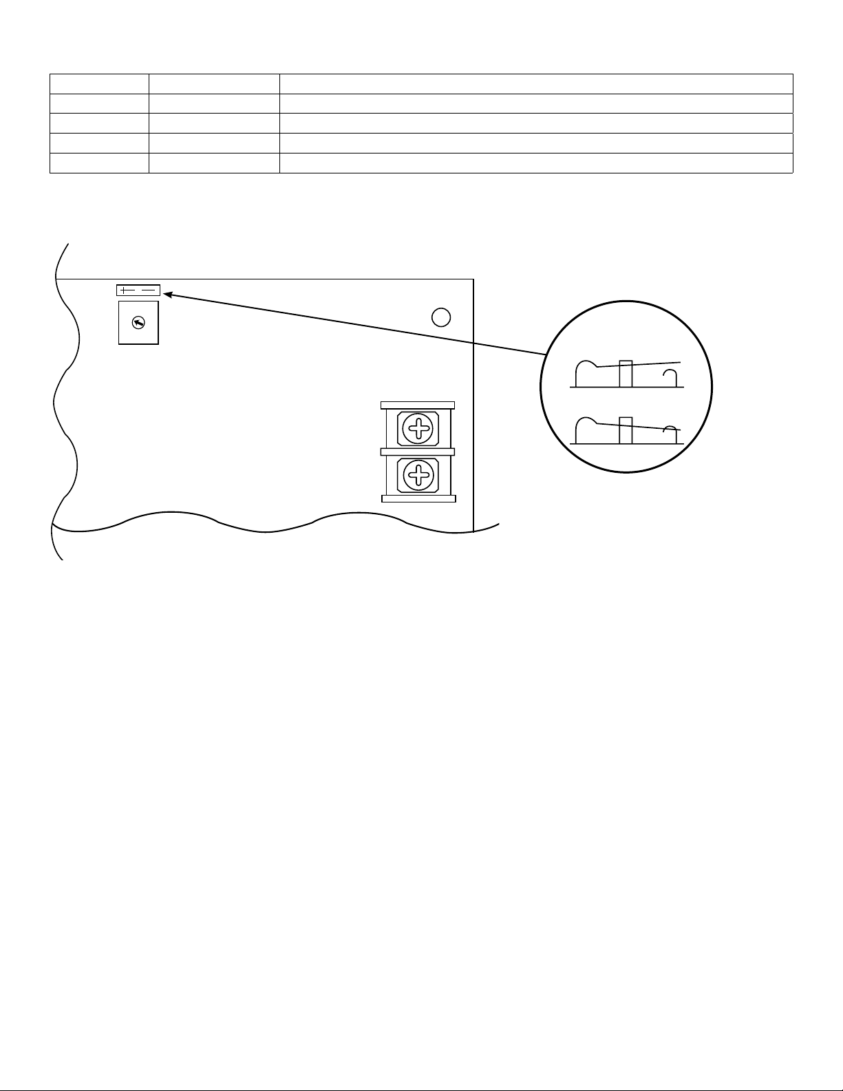
12. For Access Control Applications: mount UL Listed tamper switch (Sentrol model 3012 or equivalent) at the top of the
enclosure. Slide tamper switch bracket onto the edge or the enclosure approx. 2” from the right side (Fig. 2a, pg. 7).
Connect tamper switch wiring to the Access Control Panel input or the appropriate UL Listed reporting device.
13. Please ensure that the cover is secured with the provided key lock.
Maintenance:
Unit should be tested at least once a year for the proper operation as follows:
Output Voltage Test: Under normal load conditions the DC output voltage should be checked for proper voltage level
(MaximalFE Configuration Chart, pg. 3).
Battery Test: Under normal load conditions check that the battery is fully charged, check specified voltage at
the battery terminals and at the board terminals marked [-- BAT +] to ensure that there is no break in the battery
connection wires.
Note: Maximum charge current 1.54 amp.
Expected battery life is 5 years; however, it is recommended to change batteries within 4 years or less if necessary.
- 4 - Maximal Expandable Power Systems
Page 5

Power Supply Board Terminal Identification:
Terminal
Legend
L, G, N Connect 120VAC 60Hz to these terminals: L to hot, N to neutral. Do not use the [G] terminal
+ DC – Refer to MaximalFE Series Configuration Chart, pg. 3.
Trigger
EOL
Supervised
NO, GND
RESET
+ AUX – Auxiliary Power-Limited output rated @ 1 amp (unswitched) (power-limited output) .
AC Fail
NC, C, NO
Bat Fail
NC, C, NO
– BAT + Stand-by battery connections. Maximum charge current 1.54 amp (non power-limited).
Function/Description
Fire Alarm Interface trigger input from a short or FACP. Trigger inputs can be normally open,
normally closed from an FACP output circuit (power-limited input).
FACP interface latching or non-latching (power-limited).
Indicates loss of AC power, e.g. connect to audible device or alarm panel. Relay normally energized
when AC power is present. Contact rating 1 amp @ 30VDC (power-limited).
Indicates low battery condition, e.g. connect to alarm panel. Relay normally energized when DC power
is present. Contact rating 1 amp @ 30VDC. A removed battery is reported within 5 minutes.
Battery reconnection is reported within 1 minute (power-limited).
Power Supply Board Stand-by Battery Specifications
eFlow4NB:
Battery Access Control Applications Stand-by
7AH 30 Mins./4 amp*
12AH 35 Mins./4 amp*
40AH Over 4 Hours/4 amp*
65AH Over 4 Hours/4 amp*
eFlow6NB:
Battery Access Control Applications Stand-by
7AH 10 Mins./6 amp
12AH 30 Mins./6 amp*
40AH Over 4 Hours/6 amp*
65AH Over 4 Hours/6 amp*
eFlow102NB:
Battery Access Control Applications Stand-by
7AH 5 Mins./10 amp
12AH 30 Mins./10 amp*
40AH Over 2 Hours/10 amp*
65AH Over 4 Hours/10 amp*
eFlow104NB:
Battery Access Control Applications Stand-by
7AH 5 Mins./10 amp
12AH 30 Mins./10 amp*
40AH Over 2 Hours/10 amp*
65AH Over 4 Hours/10 amp*
*Only these configurations can be utilized in ULC-S319 installations.
Maximal Expandable Power Systems - 5 -
Page 6
OPEN SWITCH
CLOSED SWITCH
Switch Detail
Power Supply Board LED Diagnostics:
Green (DC) Green (AC/AC1) Power Supply Status
ON ON Normal operating condition.
ON OFF Loss of AC, Stand-by battery supplying power.
OFF ON No DC output.
OFF OFF Loss of AC. Discharged or no stand-by battery. No DC output.
Power Supply Board Output Voltage Settings:
Fig. 1 - eFlow4NB / eFlow6NB Power Supply Board
OPEN --- 24V
CLOSED --- 12V
Fig. 1a
--- DC +
- 6 - Maximal Expandable Power Systems
Page 7

Fig. 2
Edge of
Enclosure
to Access Control Panel
or U.L. Listed
Reporting Device
Enclosure
Sentrol
model # 3012
Tamper Switch
or equivalent
(Not Included)
Tamper Switch
OPEN --- 24V
CLOSED --- 12V
--- DC +
120VAC
Input
60 Hz.
AC DELAY SHUTDOWN
5A 250V
LGN
Line
5A 250V
Line
Neutral
LGN
Neutral
AC1
AC1
Earth
Ground
BAT FAILAC FAIL
NC C NO NC C NO
BAT FAILAC FAIL
NC C NO NC C NO
O
N
AC
DC
enable
1 min.
NO GND
TRIGGER EOL
disable
2 hr.
OPEN --- 24V
CLOSED --- 12V
AC DELAY SHUTDOWN
AC
DC
1 min.
2 hr.
RESET
SUPERVISED
O
N
enable
NO GND
TRIGGER EOL
disable
RESET
SUPERVISED
CAUTION: When power supply board is set for 12VDC
use only one (1) 12VDC stand-by battery.
Connect red battery lead to
the terminal marked [+ BAT]
and to the [positive (+)]
terminal of the battery.
+ BAT ---
Connect black battery lead to
terminal marked [BAT -- ]
and to the [negative (--)]
terminal of the battery.
Optional Rechargeable
Stand-by Battery for
UL294 Applications.
Note: 12V batteries
required for
Canadian installations.
+ AUX –
+ AUX –
--- BAT +
--- DC +
--- BAT +
Fig. 2a
Optional Rechargeable
Stand-by Battery for
UL294 Applications.
Note: 12V batteries required
for Canadian installations.
Optional Rechargeable
Stand-by Battery for
UL294 Applications.
Note: 12V batteries required
for Canadian installations.
Keep power-limited wiring separate from non power-limited.
Use minimum 0.25” spacing.
Up to four (4) 12AH Rechargeable batteries are the largest
Maximal Expandable Power Systems - 7 -
batteries that can fit in this enclosure.
A UL Listed external battery enclosure must be used
if using the 40AH or 65AH batteries.
Page 8

NEC Power-Limited Wiring Requirements:
Power-limited and non power-limited circuit wiring must remain separated in the cabinet. All power-limited circuit wiring
must remain at least 0.25” away from any non power-limited circuit wiring. Furthermore, all power-limited circuit wiring
and non power-limited circuit wiring must enter and exit the cabinet through different conduits. One such example of this
is shown below. Your specific application may require different conduit knockouts to be used. Any conduit knockouts may
be used. For power-limited applications, use of conduit is optional. All field wiring connections must be made employing
suitable gauge CM or FPL jacketed wire (or equivalent substitute).
Optional UL Listed battery enclosure must be mounted adjacent to the power supply via Class 1 wiring methods.
For Canadian installations use shielded wiring for all connections.
Note: Refer to wire handling drawing below for the proper way to install the CM or FPL jacketed wire, (Fig, 3a).
Fig. 3
Supervisory, Fire Alarm Interface
& Aux. output Connections
(power-limited)
Optional
UL Listed
Battery
Enclosure
(non power-
limited)
120VAC Input
60Hz
(non power-limited)
DC Output
Wiring
to Sub
Assemblies*
Battery Connections
(non power-limited).
Number of batteries may vary
depending on your optional hookup)
Fig. 3a
Incorrect Wire
Handling
External
Jacketed
Shield
Wire
Insulation
Solid Copper
Conductors
- 8 - Maximal Expandable Power Systems
Correct Wire
Handling
Pull back
external jacketed
shield approx. 1/2”.
*Power-limited for Maximal11FE.
Maximal13FE has one power-limited board
(eFlow4NB) and one non power-limited (eFlow6NB).
Non power-limited for Maximal33FE, Maximal35FE,
Maximal37FE, Maximal55FE, Maximal75FE,
Maximal77FE
Page 9
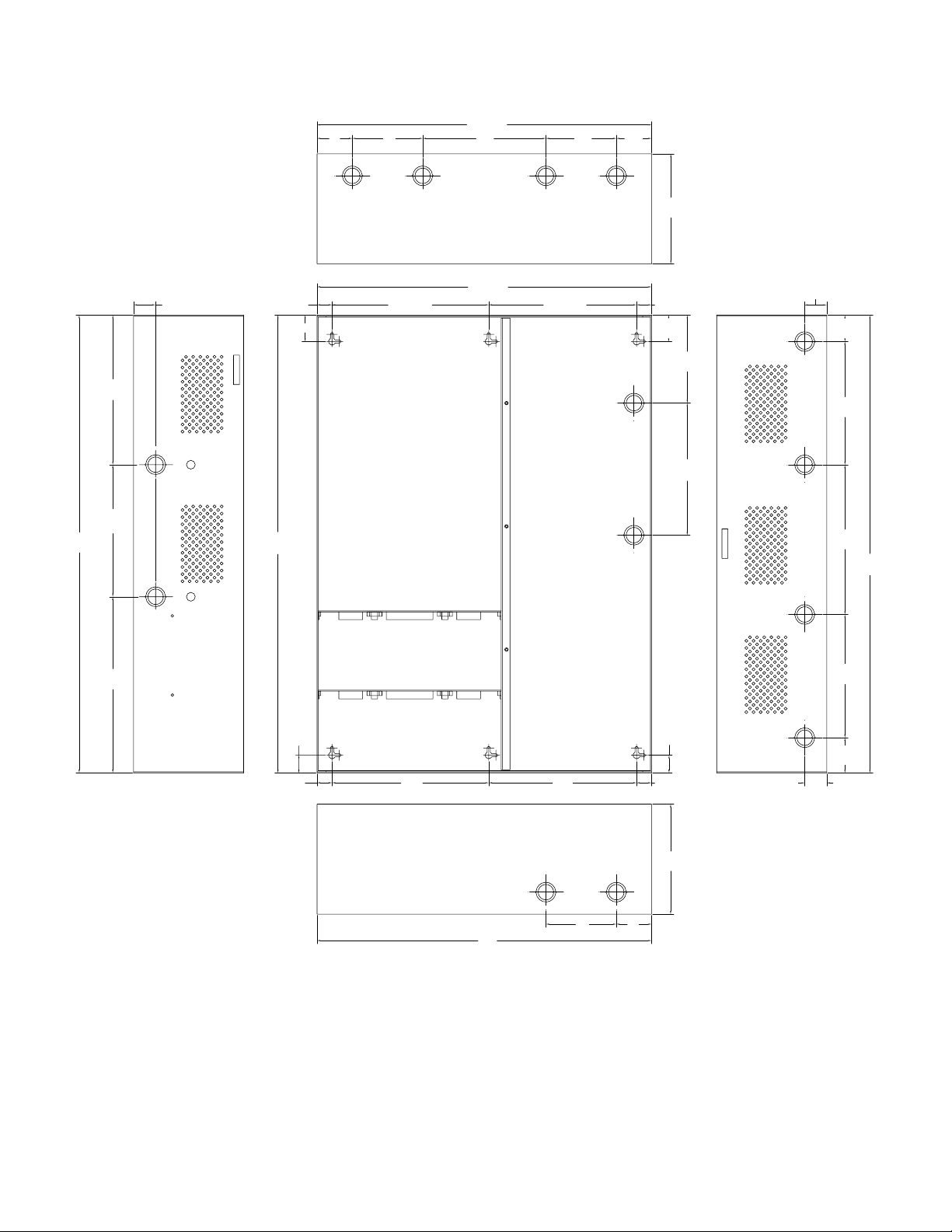
Enclosure Dimensions (H x W x D approximate):
(
)
26” x 19” x 6.25” (660.4mm x 482.6mm x 158.75mm)
19”
2”
(50.8mm)
4”
(101.6mm)
(482.6mm)
7”
(177.8mm)
TOP
4”
(101.6mm)
2”
(50.8mm)
6.25”
(158.75mm)
26”
(660.4mm)
8.5”
(215.9mm)
7.5”
(190.5mm)
10”
(254mm)
19”
1.25”
(31.75mm)
0.85”
(21.59mm)
(38.1mm)
26”
(660.4mm)
1.5”
8.9”
(226.06mm)
(482.6mm)
8.4”
(213.36mm)
0.85”
(21.59mm)
1.5”
(38.1mm)
(127mm)
(190.5mm)
5”
7.5”
LEFT RIGHT
1.25”
(31.75mm)
1.5”
(38.1mm)
7”
(177.8mm)
8.5”
(215.9mm)
(660.4mm)
7”
(177.8mm)
26”
1”
(25.4mm)
0.85”
(21.59mm)
8.9”
(226.06mm)
BOTTOM
19”
482.6mm
8.4”
(213.36mm)
(101.6mm)
4”
(50.8mm)
2”
1”
(25.4mm)
0.85”
(21.59mm)
6.25”
(158.75mm)
1.25”
(31.75mm)
2”
(50.8mm)
Maximal Expandable Power Systems - 9 -
Page 10

Notes:
Maximal Expandable Power Systems - 10 -
Page 11

Notes:
- 11 - Maximal Expandable Power Systems
Page 12

Notes:
Altronix is not responsible for any typographical errors.
140 58th Street, Brooklyn, New York 11220 USA, 718-567-8181, fax: 718-567-9056
web site: www.altronix.com, e-mail: info@altronix.com, Lifetime Warranty, Made in U.S.A.
IIMaximalFE Series F06N
MEMBER
 Loading...