

Page 1

Access Power Controllers
MaxFit3F8AP
Fully assembled kit includes:
- One (1) eFlow6NB - Power Supply/Charger
- One (1) ACM8 - Fuse Protected Access Power Controller
- One (1) PD8UL - Fuse Protected Power Distribution Module
- BC750 enclosure
MaxFit5F8AP
Fully assembled kit includes:
- One (1) eFlow102NB - Power Supply/Charger
- One (1) ACM8 - Fuse Protected Access Power Controller
- One (1) PD8UL - Fuse Protected Power Distribution Module
- BC750 enclosure
Installation Guide
Rev. MF35KF_052720
Installing Company: _____________________ Service Rep. Name: __________________________________________
More than just power.™
Address: ________________________________________________________ Phone #: _________________________
Page 2
Overview:
Tamper Switch
To Access Control Panel or
UL Listed Reporting Device
Edge of
Enclosure
Enclosure
Altronix fused Access Power Controller kits distribute and switch power to access control systems and accessories. They convert a
120VAC 60Hz input into eight (8) independently controlled 12VDC or 24VDC fuse protected outputs. These Fail-Safe/Fail-Secure power
outputs may be converted to dry form “C” contacts. Relays are activated by an open collector sink or normally open (NO) dry trigger
input from an Access Control System, Keypad, Push Button, REX PIR, etc. Units will route power to a variety of access control hardware
devices including: Mag Locks, Electric Strikes, Magnetic Door Holders, etc. The FACP Interface enables Emergency Egress, Alarm
Monitoring, or may be used to trigger other auxiliary devices. The fire alarm disconnect feature is individually selectable for any or all of
the eight (8) Fail-Safe/Fail-Secure power outputs. Additional fuse protected outputs provide power for connected devices.
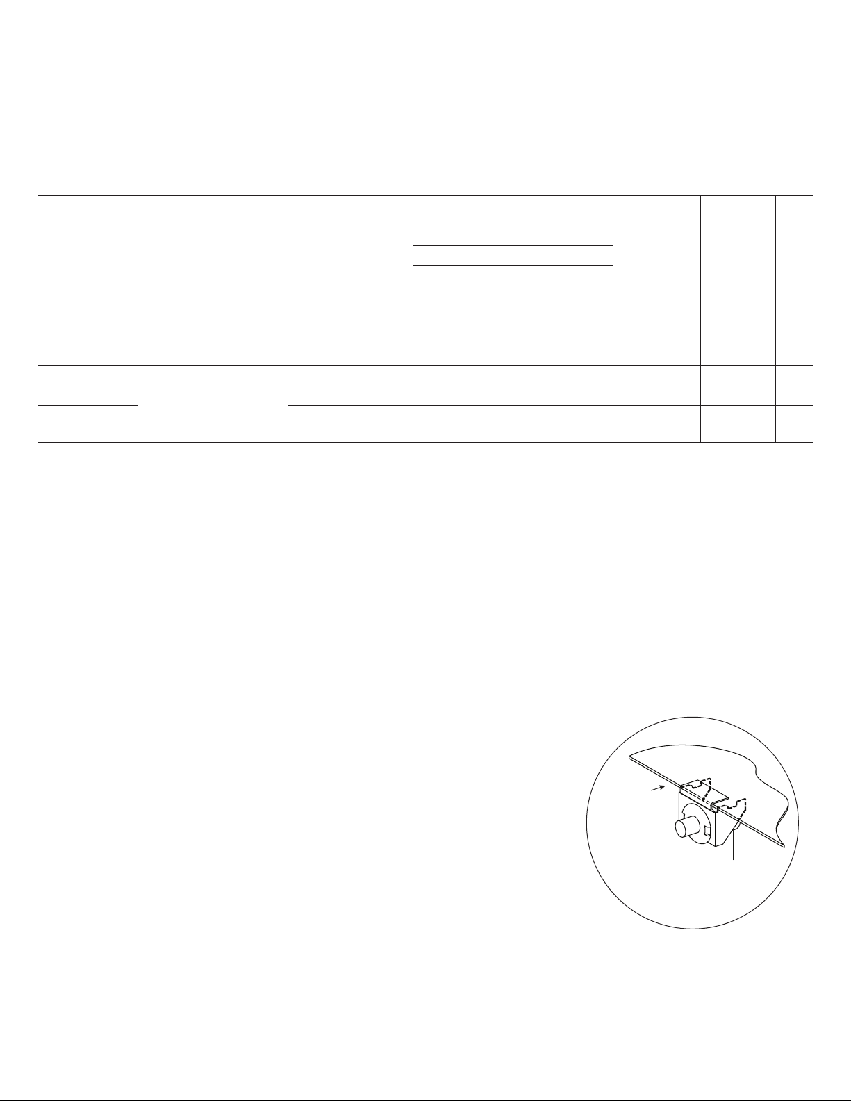
Configuration Chart:
Nominal DC
Output Voltage
[DC] [Aux]
Maximum Supply
Current for Main
and Aux. Outputs on
Power Supply board
Altronix
Model
Number
MaxFit3F8AP
MaxFit5F8AP
120VAC 60Hz
Input Current
3.5A
5A/
250V
Power Supply Board
Input Fuse Rating
15A/
32V
and ACM8 Access
Power Controller’s
Power Supply Board
Battery Fuse Rating
outputs
12VDC @ 5.4A or
24VDC @ 5.6A
12 VDC @ 9.7A
12VDC Output
Range (V)
10.0-
13.2
10.03-
13.2
20.19-
26.4
24VDC Output
Range (V)
12VDC Output
Range (V)
10.03-
13.2
10.03-
–
13.2
24VDC Output
20.19-
26.4
– 8 8
Fail-Safe/Fail-Secure or Dry
Range (V)
8 8
Form “C” Outputs
Additional Fused Outputs
ACM8 Board
Input Fuse Rating
10A/
250V
10A/
250V
ACM8 Board
Output Fuse Rating
PD8UL Board
Output Fuse Rating
2.5A/
3.5A/
250V
250V
2.5A/
3.5A/
250V
250V
Installation Instructions:
Wiring methods shall be in accordance with the National Electrical Code/NFPA 70/ANSI, and with all local codes and authorities having
jurisdiction. Product is intended for indoor use only.
1. Mount unit in desired location. Mark and predrill holes in the wall to line up with the top three keyholes in the enclosure. Install
three upper fasteners and screws in the wall with the screw heads protruding. Place the enclosure’s upper keyholes over the three
upper screws, level and secure. Mark the position of the lower three holes. Remove the enclosure. Drill the lower holes and install
the three fasteners. Place the enclosure’s upper keyholes over the three upper screws. Install the three lower screws and make sure to
tighten all screws (Enclosure Dimensions, pg. 8).
2. Connect unswitched AC power (120VAC 60Hz) to terminals marked [L, N] (Fig. 2-3, pg. 3-4). Use 14 AWG or larger for all power
connections. Secure green wire lead to earth ground.
Keep power-limited wiring separate from non power-limited wiring.
Minimum 0.25” spacing must be provided (Fig. 2-5, pg. 3-6).
CAUTION: Do not touch exposed metal parts. Shut branch circuit power before installing or servicing equipment.
There are no user serviceable parts inside. Refer installation and servicing to qualified service personnel.
3. Mount included UL Listed tamper switch (Altronix Model TS112 or equivalent) in
desired location, opposite hinge. Slide the tamper switch bracket onto the edge of the
enclosure approximately 2” from the right side (Fig. 1, pg. 2).
Connect tamper switch wiring to the Access Control Panel input or the appropriate
UL Listed reporting device. To activate alarm signal open the door of the enclosure.
4. Refer to the eFlow Power Supply/Charger Installation Guide for eFlow6NB and eFlow102NB
and corresponding Sub-Assembly Installation Guides for ACM8 and PD8UL for further
installation instructions.
Fig. 1
- 2 - MaxFit3_5F8AP
Page 3
MaxFit3F8AP: NEC Power-Limited Wiring Requirements
1 2 3 4
ON
1 2 3 4
ON
Power-limited and non power-limited circuit wiring must remain separated in the cabinet. All power-limited circuit wiring must remain at
least 0.25” away from any non power-limited circuit wiring. Furthermore, all power-limited circuit wiring and non power-limited circuit
wiring must enter and exit the cabinet through different conduits. One such example of this is shown below. Your specific application
may require different conduit knockouts to be used. Any conduit knockouts may be used. For power-limited applications use of conduit is
optional. All field wiring connections must be made employing suitable gauge CM or FPL jacketed wire (or equivalent substitute). Optional
UL Listed battery enclosure must be mounted adjacent to the power supply via Class 1 wiring methods. For Canadian installations use
shielded wiring for all connections.
Note: Refer to wire handling drawing below for the proper way to install the CM or FPL jacketed wire (Fig. 2a).
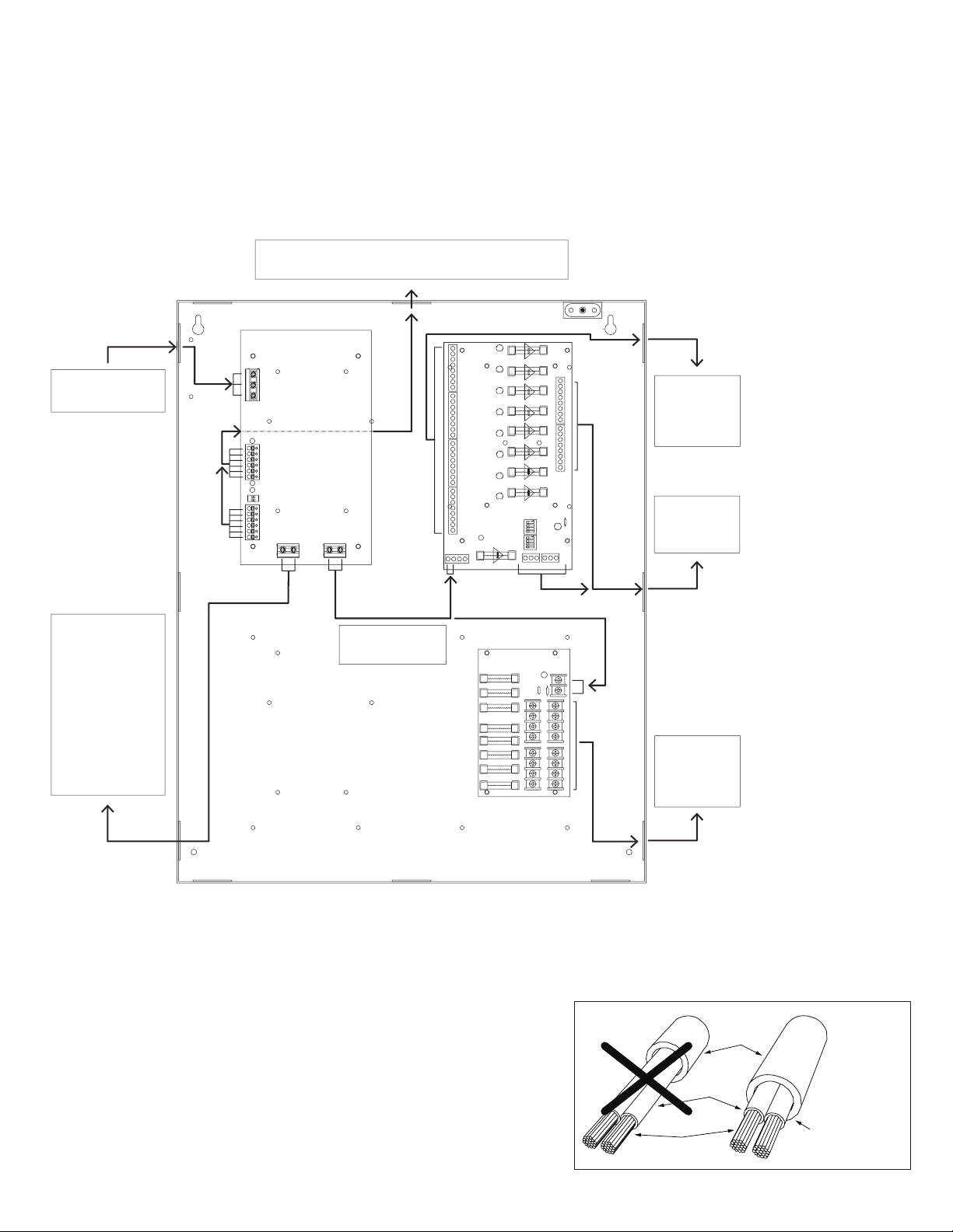
Fig. 2
Supervisory Connections, Aux. DC Output to Devices and
Fire Alarm Interface (power-limited)
Tamper Switch
NC C NO COM NC C NO COM NC C NO COM NC C NO COM NC C NO COM NC C NO COM NC C NO COM NC C NO COM
Input 120VAC, 60Hz
(non power-limited)
OUTPUT 1 OUTPUT 2 OUTPUT 3 OUTPUT 4 OUTPUT 5 OUTPUT 6 OUTPUT 7 OUTPUT 8
L G N
eFlow6NB
F1 F2 F3 F4 F5 F6 F7 F8
1 2 3 4
IN GND IN GND IN GND IN GNDIN GND IN GND IN GND IN GND
5 6 7 8
INPUT
TRIGGER
ACM8 Outputs
to Devices
(non power-
limited)
FACP
ON
1 2 3 4
ON
1 2 3 4
NO C NC
FACP INTERFACE
+INP- T + RET-
LED
D1
R1
TRG
(power-limited)
INPUT
P N
Optional
Rechargeable
Stand-by Batteries
for UL294
Applications
– DC +– BAT +
DC Output
(non power-limited)
- + - +
Power Control
ACM8
10A 250V
MAIN
PD8UL
Note:
12V batteries
are required for
ULC-S319
installations.
FUSED POWER OUTPUTS
COMMON POWER OUTPUTS
1 2 3 4 5 6 7 8
N
P
PD8UL Outputs
Connect red battery lead to the terminal marked [+ BAT] and to the [positive (+)] terminal of the battery.
Connect black battery lead to terminal marked [BAT –] and to the [negative (–)] terminal of the battery.
Keep power-limited wiring separate from non power-limited. Use minimum 0.25" spacing.
12AH Rechargeable batteries are the largest batteries that can fit in this enclosure.
A UL listed external battery enclosure must be used if using the 40AH or 65AH batteries.
Incorrect Wire
Handling
Supervisory
Connections
to Devices
(non power-
limited)
External
Jacketed
Shield
Fig. 2a
Correct Wire
Handling
Wire
Insulation
Pull back
external jacketed
Solid Copper
shield approx. 1/2”.
Conductors
MaxFit3_5F8AP - 3 -
Page 4

MaxFit7F5AP: NEC Power-Limited Wiring Requirements
1 2 3 4
ON
1 2 3 4
ON
Power-limited and non power-limited circuit wiring must remain separated in the cabinet. All power-limited circuit wiring must remain at
least 0.25” away from any non power-limited circuit wiring. Furthermore, all power-limited circuit wiring and non power-limited circuit
wiring must enter and exit the cabinet through different conduits. One such example of this is shown below. Your specific application
may require different conduit knockouts to be used. Any conduit knockouts may be used. For power-limited applications use of conduit is
optional. All field wiring connections must be made employing suitable gauge CM or FPL jacketed wire (or equivalent substitute). Optional
UL Listed battery enclosure must be mounted adjacent to the power supply via Class 1 wiring methods. For Canadian installations use
shielded wiring for all connections.
Note: Refer to wire handling drawing below for the proper way to install the CM or FPL jacketed wire (Fig. 3a).
Fig. 3
Supervisory Connections, Aux. DC Output to Devices and
Fire Alarm Interface (power-limited)
Tamper Switch
NC C NO COM NC C NO COM NC C NO COM NC C NO COM NC C NO COM NC C NO COM NC C NO COM NC C NO COM
OUTPUT 1 OUTPUT 2 OUTPUT 3 OUTPUT 4 OUTPUT 5 OUTPUT 6 OUTPUT 7 OUTPUT 8
L G N
Input 120VAC, 60Hz
(non power-limited)
eFlow102NB
F1 F2 F3 F4 F5 F6 F7 F8
1 2 3 4
IN GND IN GND IN GND IN GNDIN GND IN GND IN GND IN GND
5 6 7 8
INPUT
TRIGGER
ACM8 Outputs
to Devices
(non power-
limited)
FACP
ON
1 2 3 4
ON
1 2 3 4
NO C NC
FACP INTERFACE
+INP- T + RET-
LED
D1
R1
TRG
(power-limited)
INPUT
P N
Optional
Rechargeable
Stand-by Batteries
for UL294
Applications
– DC +– BAT +
DC Output
(non power-limited)
- + - +
Power Control
ACM8
10A 250V
MAIN
PD8UL
Note:
12V batteries
are required for
ULC-S319
installations.
FUSED POWER OUTPUTS
COMMON POWER OUTPUTS
1 2 3 4 5 6 7 8
N
P
PD8UL Outputs
Connect red battery lead to the terminal marked [+ BAT] and to the [positive (+)] terminal of the battery.
Connect black battery lead to terminal marked [BAT –] and to the [negative (–)] terminal of the battery.
Keep power-limited wiring separate from non power-limited. Use minimum 0.25" spacing.
12AH Rechargeable batteries are the largest batteries that can fit in this enclosure.
A UL listed external battery enclosure must be used if using the 40AH or 65AH batteries.
Incorrect Wire
Handling
Supervisory
Connections
to Devices
(non power-
limited)
External
Jacketed
Shield
Fig. 3a
Correct Wire
Handling
Wire
Insulation
Pull back
external jacketed
Solid Copper
shield approx. 1/2”.
Conductors
- 4 - MaxFit3_5F8AP
Page 5

Notes:
MaxFit3_5F8AP - 5 -
Page 6

Notes:
- 6 - MaxFit3_5F8AP
Page 7

eFlow Power Supply/Chargers can be Controlled and Monitored while
Reporting Power/Diagnostics from Anywhere over the Network...
LINQ2 - Network Communication Module
LINQ2 provides remote IP access to real-time data from eFlow power supply/chargers to help keep
systems up and running at optimal levels. It facilitates fast and easy installation and set-up, minimizes system downtime, and eliminates unnecessary service calls, which helps reduce Total Cost
of Ownership (TCO) - as well as creating a new source of Recurring Monthly Revenue (RMR).
LINQ2
Features:
- UL Listed in the U.S. and Canada.
- Local or remote control of up to (2) two Altronix eFlow power output(s) via LAN and/or WAN.
- Monitor real time diagnostics: DC output voltage, output current, AC & battery status/service, input trigger state change,
output state change and unit temperature.
- Access control and user managment: Restrict read/write, Restrict users to specific resources
- Two (2) integral network controlled Form “C” Relays.
- Three (3) programmable input triggers: Control relays and power supplies via external hardware sources.
- Email and Windows Dashboard notifications
- Event log tracks history.
- Secure Socket Layer (SSL).
- Programmable via USB or web browser - includes operating software and 6 ft. USB cable.
LINQ2 Mounts Inside any MaxFit Enclosure
Network Connection:
Installation, Programming
and Monitoring
Altronix
eFlow
Power
Supply
MaxFit3_5F8AP - 7 -
Page 8

MaxFit Enclosure Dimensions (approximate):
20.5” x 16.5” x 6.25” (520.7mm x 419.1mm x 158.8mm)
1.50”
(38.1mm)
6.25” (158.8mm)
1.25” (31.8mm)
0.569” (14.5mm)
8.75” (222.3mm)8.75” (222.3mm)
1.25” (31.8mm)
7.00” (177.8mm) 7.00” (177.8mm)
16.50” (419.1mm)
0.75” (19.1mm)
1.25” (31.8mm)
1.00” (25.4mm)
1.25” (31.8mm)
1.25” (31.8mm)
1.25” (31.8mm)
1.50” (38.1mm)
8.75” (222.3mm)8.75” (222.3mm)
1.50”
(38.1mm)
1.25” (31.8mm)
1.25” (31.8mm)
7.00” (177.8mm) 7.00” (177.8mm)
20.50” (520.7mm)
1.50” (38.1mm)
1.25” (31.8mm)
1.25” (31.8mm)
1.25” (31.8mm)
Altronix is not responsible for any typographical errors.
140 58th Street, Brooklyn, New York 11220 USA | phone: 718-567-8181 | fax: 718-567-9056
web site: www.altronix.com | e-mail: info@altronix.com | Lifetime Warranty | Made in U.S.A.
IIMaxFit3,5F8AP E27T
- 8 - MaxFit3_5F8AP
MEMBER
 Loading...