

Page 1
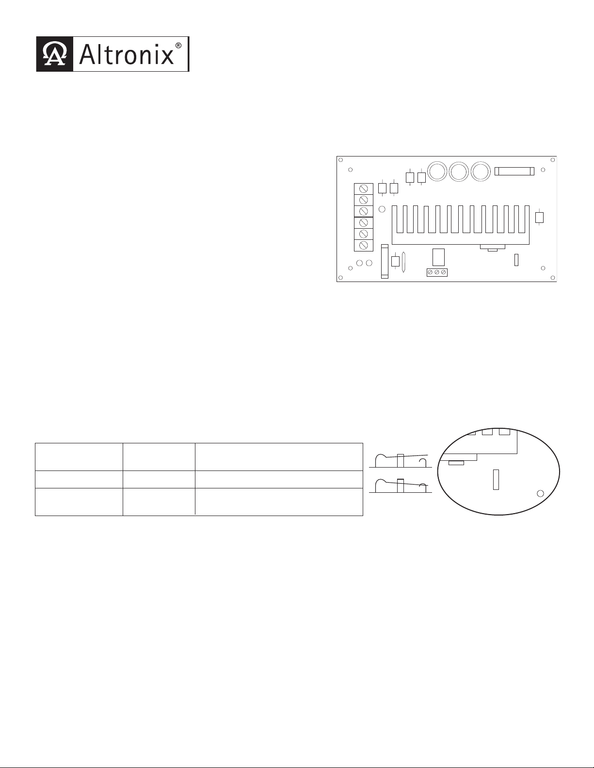
LPS3/LPS3R - Linear Power Supply/Charger
A
C
D
C
AC
AC FAIL
C
ONTACTS
AC
-- DC +
-- BAT +
NC C NO
SW1
1
2V-CLOSED
24V-OPEN
OPEN SWITCH
CLOSED SWITCH
Switch Detail
SW1
12V-CLOSED
24V-OPEN
Overview:
LPS3/LPS3R linear power supply/chargers will convert a low voltage AC input to a low voltage 12VDC/24VDC output.
These power supplies are specifically designed to provide to power needed by the most demanding security and access
control applications.
Specifications:
Input:
• 16VAC or 28VAC
(
refer to voltage output/transformer selection chart).
Output:
• 12VDC/24VDC selectable output.
2.5 amp continuous supply current.
•
• Filtered and electronically regulated output.
• Thermal overload and short circuit protection.
Battery Backup:
• Built-in charger for sealed lead acid or gel type batteries.
• Maximum charge current 500mA.
• Automatic switch over to stand-by battery.
• Fused battery protection (circuit breaker available).
• Includes battery leads.
Visual Indicators:
• AC input and DC output LED indicators.
Board Dimensions (approximate):
6.5”L x 3.5”W x 1.75”H
Specified at 25˚ C ambient.
Voltage Output/Transformer Selection Table:
Output Voltage Switch Transformer Requirements
Position (Recommended Altronix Part #’s)
Supervision:
• LPS3R is the same as LPS3 w/ AC Fail
supervision (Form “C” contacts.)
Fig. 1
12VDC Closed 16VAC / 56 VA (T1656).
24VDC
Open
24VAC or 28VAC / 100VA
(Altronix model T2428100)
Note: Transformers with higher VA ratings may be used.
Installation Instructions:
The LPS3/LPS3R should be installed in accordance with The National Electrical Code and all applicable Local
gulations.
Re
Mount the LPS3/LPS3R in desired location / enclosure.
1.
2. Set DC output voltage using switch SW2
3. Connect proper transformer to terminals marked AC
(refer to voltage output/transformer selection table).
(refer to voltage output/transformer selection table).
4. Measure output voltage before connecting devices. This helps avoid potential damage.
5. Connect devices to be powered to terminals marked [ --- - DC +].
6. When the use of stand-by batteries are desired, they must be lead acid or gel type.
Connect battery to terminals marked [+ BAT --- ] on the unit (battery leads included).
Use two (2) 12VDC batteries connected in series for 24VDC operation.
7. When batteries are not used a loss of AC will result in the loss of output voltage.
y trouble reporting devices to outputs marked [AC Fail] (LPS3R only).
visor
Connect super
8.
Page 2
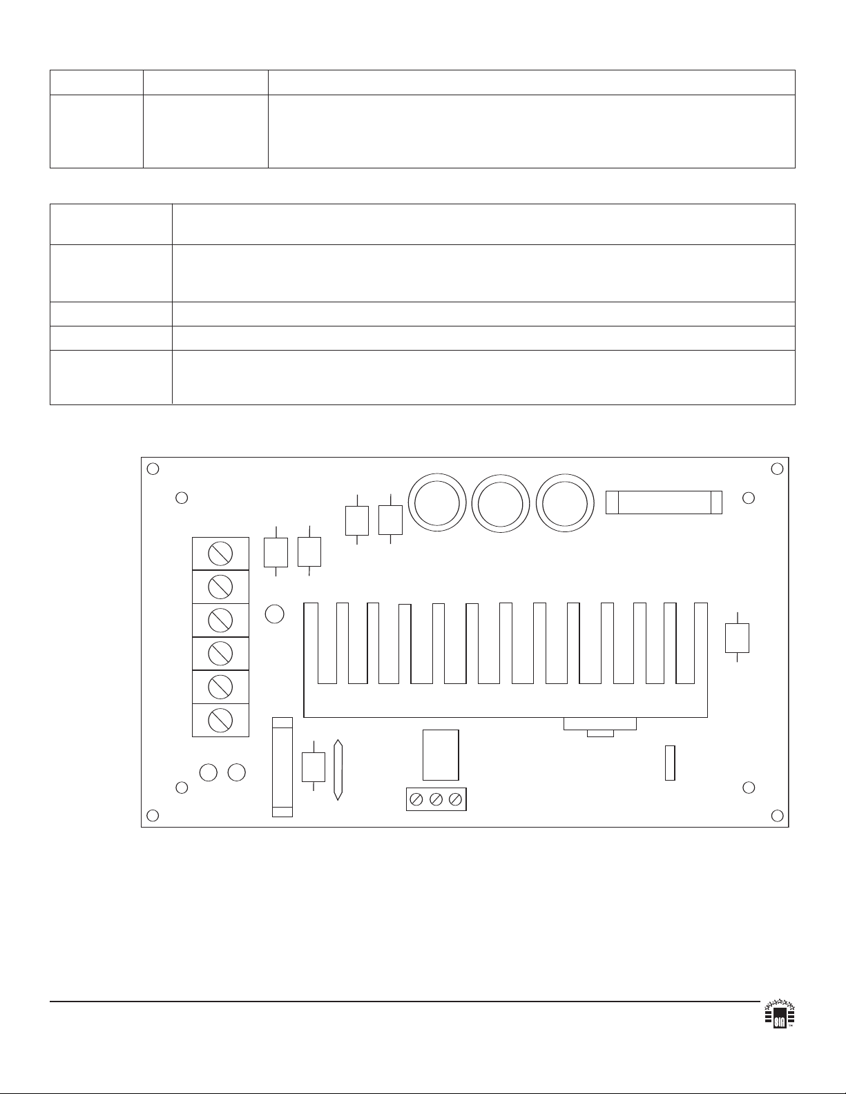
LED Diagnostics:
AC
DC
AC
AC FAIL
CONTACTS
AC
-- DC +
-- BAT +
NC C NO
SW1
12V-CLOSED
24V-OPEN
Red (DC) Green (AC) Power Supply Status
O
N ON Normal operating condition.
ON OFF Loss of AC, Stand-by battery supplying power.
OFF ON No DC output. Short circuit or thermal overload condition or defective unit.
OFF OFF No DC output. Loss of AC. Discharged or no battery present.
Terminal Identification:
Terminal Function/Description
Legend
AC/ AC Low voltage AC input (see voltage output/transformer selection table).
For 12VDC output use 16VAC with 56VA power rating or higher.
For 24VDC output use 28VAC with 85VA power rating or higher.
--- DC + 12VDC-24VDC @ 2.5 amp continuous output.
+ BAT --- Stand-by battery connections. Maximum charge rate 500mA.
AC FAIL Used to report loss of AC (e.g. connect to audible device or alarm panel).
.C., C, N.O. Relay normally energized when AC power is present.
N
(LPS3R only) Contact rating 1 amp @ 120VAC / 28VDC.
graphical errors. Product specifications are subject to change without notice.
y typo
le for an
. 081004
v
Altronix is not responsib
140 58th Street, Brooklyn, New York 11220 USA, 718-567-8181, fax: 718-567-9056
website: www.altronix.com, e-mail: info@altronix.com, Lifetime Warranty, Made in U.S.A.
IILPS3/LPS3R - Re
K15F
MEMBER
 Loading...