

Page 1
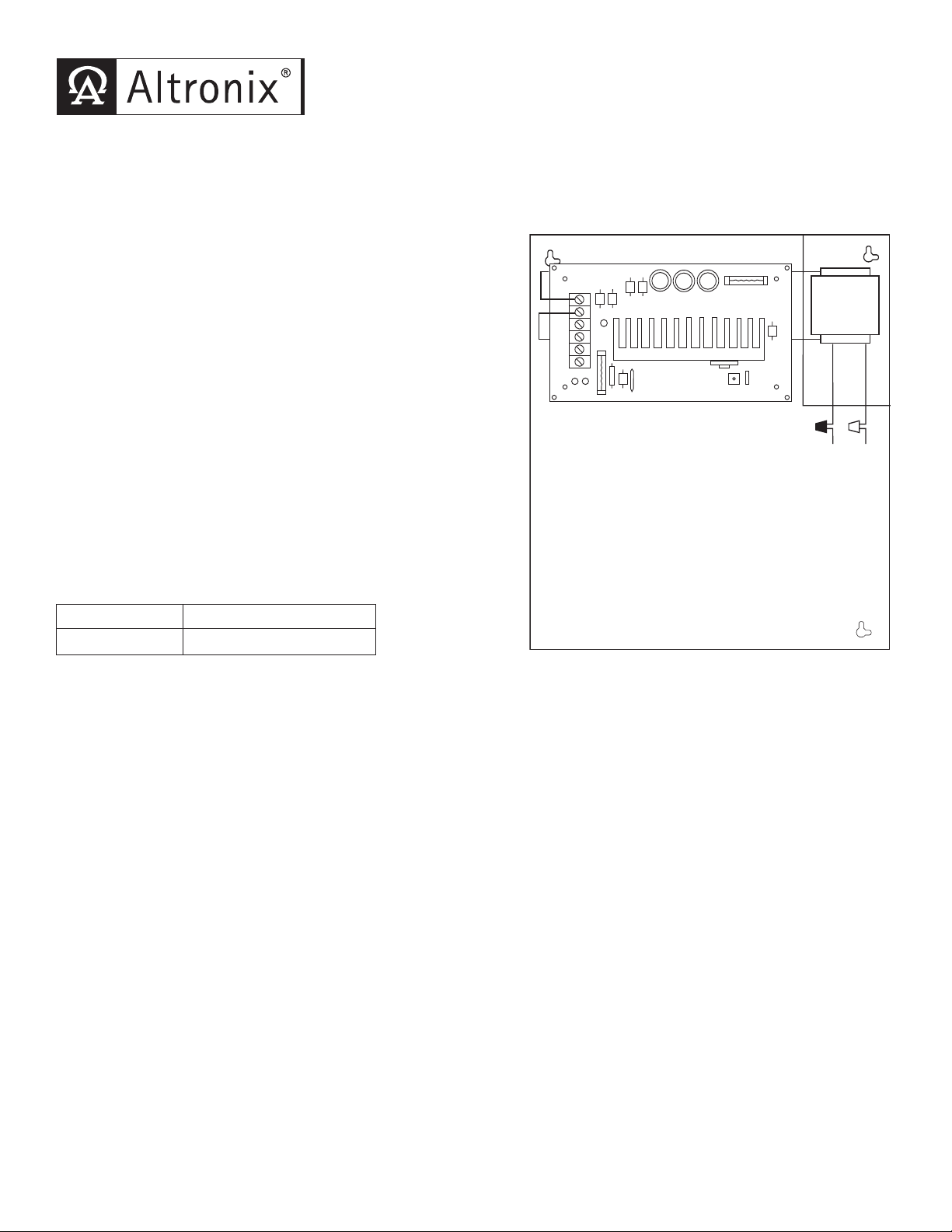
LPS3C12X
XFMR
White
Lead
Black
Lead
Input 115VAC
50/60Hz
.5 amp
AC
DC
AC
AC
-- DC +
-- BAT +
SW1
12V-CLOSED
24V-OPEN
Linear Power Supply/Charger
Overview:
LPS3C12X linear power supply/charger is specifically designed to provide the power needed by the most demanding
security and access control applications. It will convert a 115VAC 50/60Hz input to a 2.5 amp, 12VDC output.
Specifications:
Input:
• Input 115VAC 50/60Hz, .5 amp.
Output:
• 12VDC output.
• 2.5 amp continuous supply current.
• Filtered and electronically regulated output.
• Thermal and short circuit protection with auto reset.
Battery Backup:
• Automatic switch over to stand-by battery when AC Fails.
• Built-in charger for sealed lead acid or gel type batteries.
• Maximum charge current .5 amp.
• Fused battery protection (circuit breakers available).
• Includes battery leads.
Visual Indicators:
• AC input and DC output LED indicators.
Enclosure Dimensions:
15.5”H x 12”W x 4.5”D
Power Supply Voltage Output Specifications:
Output VDC Maximum Load DC
12VDC 2.5 amp
Installation Instructions:
The LPS3C12X should be installed in accordance with The National Electrical Code and all applicable
Local Regulations.
1. Mount the LPS3C12X in desired location.
2. Connect AC power to the black and white flying leads of the transformer (Fig. 1).
Use 18 AWG or larger for all power connections (Battery, DC output).
Measure output v
3.
4. Connect devices to be powered to terminals marked [- DC +]
5. Connect battery to terminals marked [- BAT +]
Note: When batteries are not used a loss of AC will result in loss of output voltage.
Maintenance:
Unit should be tested at least once a y
Output Voltage Test: Under normal load conditions, the DC output voltage should be checked for proper voltage level
(Power Supply Voltage Output Specifications Chart).
y Test: Under normal load conditions check that the battery is fully charged, check specified voltage both at
Batter
battery terminal and at the board terminals marked [- BAT +] to insure there is no break in the battery connection wires.
Note: Maximum charging current under discharge is 500mA.
Note: Expected battery life is 5 years, however it is recommended changing batteries in 4 years or less if needed.
oltage before connecting devices. This helps avoid potential damage.
(Fig. 1).
(Fig. 1) on the unit (battery leads included).
ws:
ear for the proper operation as follo
Fig. 1
Page 2
LED Diagnostics:
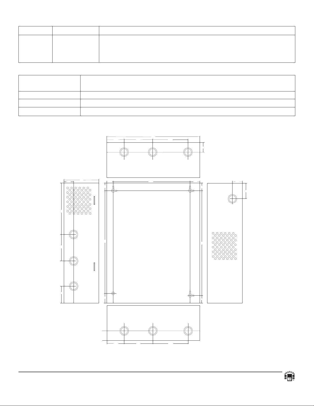
.875"
1"
1.3"
9.97"
13.53"
6.625"
2.25"
3.68"
4.56"
1.22"
1.22"
3.5"
1"
13.25"
2"
1.22"
12"
15.5"
4.5"
2.25"
3.68"
4.56"
1.22"
1.25"
2.2"
1"
Red (DC) Green (AC) Power Supply Status
ON
ON Normal operating condition.
ON OFF Loss of AC, Stand-by battery supplying power.
OFF ON No DC output.
OFF OFF Loss of AC. Discharged or missing stand-by battery. No DC output.
Terminal Identification:
Terminal Function/Description
Legend
AC/AC Low voltage AC input (16VAC 56VA). Altronix part #T1656.
--- BAT + Stand-by battery connections.
--- DC + 12VDC @ 2.5 amp continuous output.
Enclosure Dimensions:
15.5”H x 12”W x 4.5”D
Altronix is not responsible for any typographical errors. Product specifications are subject to change without notice.
140 58th Street, Brooklyn, New York 11220 USA, 718-567-8181, fax: 718-567-9056
website: www.altronix.com, e-mail: info@altronix.com, Lifetime
IILPS3C12X - Rev. 110801 K24D
Warranty, Made in U.S.A.
MEMBER
 Loading...