

Page 1

Please be sure to visit
altronix.com for
latest firmware and
installation instructions
Dual Input Network
Access Power Controllers
Installation and Programming Manual
Models include:
LINQ8ACM
- Network Access Power Controller
- Eight (8) Fused Outputs
LINQ8ACMCB
- Network Access Power Controller
- Eight (8) PTC Outputs
DOC#: LINQ8ACM Rev. 100219
More than just power.
TM
Page 2

Altronix LINQ8ACM(CB) are dual input network access power controllers which can be installed in Altronix wall
and rack mount enclosures to facilitate access control deployment. Access Power Controller’s dual input design
allows power to be steered from one (1) or two (2) independent low voltage 12 or 24 VDC Altronix power supplies
to eight (8) independently controlled fuse (LINQ8ACM) or PTC (LINQ8ACMCB) protected outputs. Outputs are
activated by an open collector sink, normally open (NO), normally closed (NC) dry trigger input, or wet output
from an Access Control System, Card Reader, Keypad, Push Button, PIR, etc. LINQ8ACM(CB) will route power
to a variety of access control hardware devices including Mag Locks, Electric Strikes, Magnetic Door Holders,
etc. Outputs will operate in both Fail-Safe and/or Fail-Secure modes. The FACP Interface enables Emergency
Egress, Alarm Monitoring, or may be used to trigger other auxiliary devices. The fire alarm disconnect feature
is individually selectable for any or all of the eight (8) outputs. The spade connectors allow you to daisy chain
power to multiple LINQ8ACM(CB) modules. This feature allows you to distribute the power over more outputs
for larger systems. Built-in LINQTM Network Power Management facilitates monitoring, reporting and control
of power/diagnostics.
Specifications:
Input Voltage Options:
Overview:
• Single Input:
Input1: 12 or 24 VDC from eFlow series power supply.
• Dual Input Option 1:
- Input 1: 12 or 24 VDC from eFlow series power supply.
- Input 2:
a - 12 or 24 VDC from eFlow series power supply.
b - 5 or 12 VDC from VR6 voltage regulator.
• Dual Input Option 2: 24 and 12 VDC from Tango1B PoE Driven Power Supply.
• Input Current:
LINQ8ACM: 20A total
LINQ8ACMCB: 16A total.
• Eight (8) trigger inputs:
a) Normally open (NO) inputs (dry contacts).
b) Normally closed (NC) inputs (dry contacts).
c) Open collector sink inputs.
d) Wet Input (5VDC - 24VDC) with 10K resistor.
e) Any combination of the above.
Outputs:
• LINQ8ACM:
Fuse protected outputs rated @ 2.5A per output, non power-limited. Total output 20A max.
LINQ8ACMCB:
PTC protected outputs rated @ 2A per output, Class 2 power-limited. Total output 16A max.
Do not exceed the individual power supply ratings.
See Input/Output Voltage Ratings, pg. 6.
See Maximum Output of Altronix Power Supplies.
• Eight (8) selectable independently controlled outputs (see below for ratings):
a) Fail-Safe and/or Fail-Secure power outputs.
b) Auxiliary power outputs (unswitched).
c) Any combination of the above.
• Individual outputs may be set to OFF position for servicing (output jumper set to middle position).
• Any of the eight (8) fuse/PTC protected power outputs are selectable to follow power Input 1 or Input 2.
Output voltage of each output is the same as the input voltage of the input selected.
See Input/Output Voltage Ratings, pg. 6.
• Surge suppression.
Programmable Features:
• Eight (8) programmable outputs:
- Fail-safe, fail-secure or auxiliary outputs.
- Input controlled or manually controlled through software.
- High (over) and low (under) voltage and current monitoring by output.
- Multiple outputs may be programmed to be triggered by a single input.
- Battery back-up by output.
- 2 - LINQ8ACM(CB)
Page 3

• Eight (8) programmable trigger inputs:
OFF
PWR2
PWR1
- Normally open (NO).
- Normally colsed (NC).
- Open collector sink inputs.
- Wet Input (5VDC - 24VDC) with 10k resistor.
- Any combination of the above.
• Programmable port IDs.
• Monitor power supply(ies) input for voltage and currect limits (high/low).
• Input and output current calibration.
• Programmable timer events.
• Programmable user levels.
• Enable or disable alerts by type.
• Programmable alert reporting delay/
Fire Alarm Disconnect:
• Fire Alarm disconnect (Inactive, latching or non-latching) is individually selectable for any or all of
the eight (8) outputs.
Fire Alarm disconnect input options:
a) Supervised Normally Open [NO] or Normally Closed [NC] dry contact input.
b) Polarity reversal input from FACP signaling circuit.
• FACP input WET is rated 5-30VDC 7mA.
• FACP dry input EOL requires 10K end of line resistor.
• FACP output relay [NC]: Either Dry 1A/28VDC, 0.6 Power Factor or 10K resistance with [EOL JMP] intact.
Fuse Ratings:
• Main input fuses rated 15A/32V each.
• LINQ8ACM: Output fuses are rated 3A/32V.
• LINQ8ACMCB: Output PTCs are rated 2A.
LED Indicators:
• Green AC LED: indicates AC trouble condition.
• Green BAT LED: indicates battery trouble condition.
• Green FACP LED: indicates FACP disconnect is triggered.
• Flashing Blue Heartbeat LED: indicates network connection.
• Individual OUT1 - OUT8 Red LEDs: indicate outputs are triggered.
• Individual Voltage LEDs: indicate 12VDC (Green) or 24VDC (Red).
Environmental:
• Operating temperature: 0ºC to 49ºC ambient.
• Humidity: 20 to 93%, non-condensing.
Mechanical:
• Board Dimensions (W x L x H approximate): 8” x 4.5” x 1.25” (203.2mm x 114.3mm x 31.8mm).
• Product weight (approx.): 0.7 lb. (0.32 kg).
• Shipping weight (approx.): 0.95 lb. (0.43 kg).
Wiring methods shall be in accordance with the National Electrical Code NFPA 70/NFPA 72/ ANSI / Canadian
Electrical Code / CAN/ULC-S524/ULC-S527/ULC-S537, and with all local codes and authorities having
jurisdiction. Product is intended for indoor dry use only.
Refer to Sub-Assembly Installation Instruction for mounting Rev. MS020119.
Carefully review:
Terminal/Connector Identification (pg. 5) Typical Application Diagram (pg. 9)
LED Diagnostics (pg. 6) Hook-up Diagrams (pg. 15-16)
1. Mount LINQ8ACM(CB) in the desired location/enclosure. When mounting LINQ8ACM(CB) alone,
use female/female spacers (provided). When mounting with optional VR6 voltage regulator or Tango1B PoE
Driven Power Supply, use female/female spacers (provided) between LINQ8ACM(CB) and VR6 or Tango1B
(Fig. 3, pg. 7, Fig. 4, pg. 8).
2. Ensure all output jumpers [OUT1] - [OUT8] are placed in the OFF (center) position.
3. Connect low voltage DC power supplies to terminals marked [+ PWR1 –], [+ PWR2 –].
Note: For VR6 and Tango1B installation please refer to pg. 7, 8.
4. Set each output [OUT1] - [OUT8] to route power from Power Supply 1 or 2 (Fig. 1).
Note: Measure output voltage before connecting devices.
This helps avoiding potential damage.
5. Turn main power off before connecting devices.
LINQ8ACM(CB) - 3 -
Installation Instructions:
Fig. 1
Page 4
6. Output Options (program output options via LINQ software):
LINQ8ACM(CB) will provide up to eight (8) switched power outputs plus eight (8) unswitched auxiliary
power outputs.
Switched Power outputs:
Connect the negative (–) input of the device being powered to the terminal marked [COM].
• For Fail-Safe operation connect the positive (+) input of the device being powered to the terminal
marked [NC].
• For Fail-Secure operation connect the positive (+) input of the device being powered to the terminal
marked [NO].
Auxiliary Power Outputs (unswitched):
Connect positive (+) input of the device being powered to the terminal marked [C] and the negative (–)
of the device being powered to the terminal marked [COM]. Output can be used to provide power for
card readers, keypads etc.
7. Turn main power on after all devices are connected.
8. Input Trigger Options (program trigger input options via LINQ software):
Note: If Fire Alarm disconnect is not used, connect a 10 kOhm resistor to terminals marked [GND and EOL].
Input:
Connect dry access control (NC/NO) input to terminals marked [+ INP1 –] to [+ INP8 –].
Open Collector Sink Input:
Connect the open collector sink input to the terminal marked [+ INP1 –] to [+ INP8 –].
Wet (Voltage) Input Configuration:
Carefully observing polarity, connect the voltage input trigger wires and the supplied 10K resistor to
terminals marked [+ INP1 –] to [+ INP8 –].
9. Fire Alarm Interface Options (program fire alarm interface options via LINQ software):
A normally closed [NC], normally open [NO] input or polarity reversal input from FACP signaling circuit
will trigger selected outputs.
Normally Open Input:
Wire your FACP relay and 10K resistor in parallel on terminals marked [GND] and [EOL].
Normally Closed Input:
Wire your FACP relay and 10K resistor in series on terminals marked [GND] and [EOL].
10. FACP Dry NC output:
Connect desired device to be triggered by the unit’s dry contact output to the terminals marked [NC] and [C].
When [EOL JMP] is in the DIS position, the output is of 0 Ohm resistance in a normal condition.
When [EOL JMP] is in the EN position, a 10k resistance will be passed to next device when in a
normal condition.
Fig. 2 - LINQ8ACM
QRS
P
X
+PWR2
Y
+PWR2 +PWR1
+ PWR1 - + PWR2 -
A
B
BAT AC
NC C NO
NC C NO
U
C
D
E
OUT1
PWR2<-->PWR1
NO C NC COM NO C NC COM NO C NC COM NO C NC COM NO C NC COM NO C NC COM NO C NC COM NO C NC COM
COM -
Y
OUT2
PWR2<-->PWR1
Tamper
+ INP1 -+ INP2 -+ INP3 -+ INP4 -
Out4
Out3
Out6
Out5
Out2
Out1
Beat
FACP
BAT
AC
OUT3
PWR2<-->PWR1
PWR2<-->PWR1
T
Out7
Out8
OFF
PWR2
PWR1
+ INP5 -+ INP6 -+ INP7 -+ INP8 -
V
W
OUT4
OUT5
PWR2<-->PWR1
PWR2<-->PWR1
OUT7
OUT6
PWR2<-->PWR1
F
+PWR1
Z
OUT8
PWR2<-->PWR1
BAT 1 FUSE BAT 2 FUSE
E
EN<-->DIS
COM -
+ PS1 - + BAT - + PS2 - + BAT -
F+ R+ EOL RST NC FACP
F- R- GND GND C
- 4 - LINQ8ACM(CB)
O
N
M
L
K
J
I
H
G
Page 5

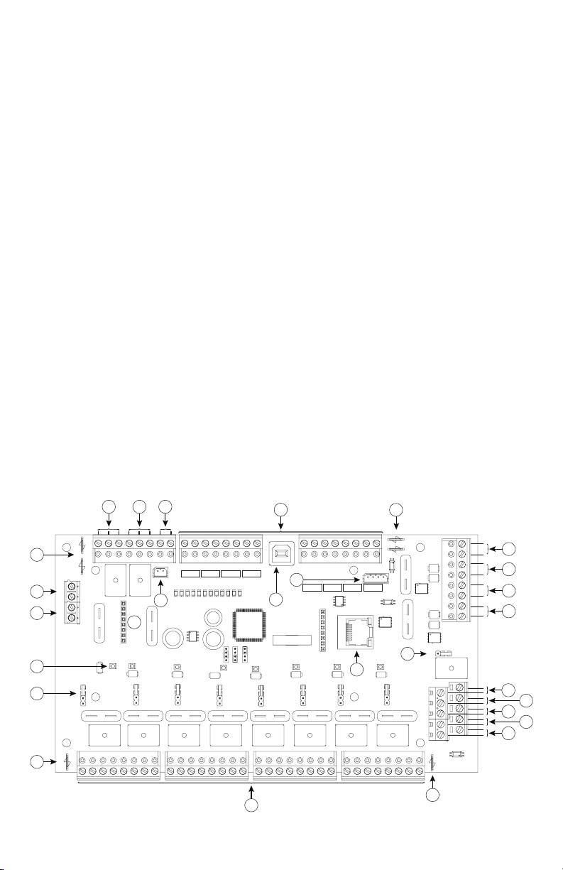
Terminal/Connector Identification:
ABCDEFGHIJKLMNOPQRST
UVWXY
Z
H
IJKLMNOPQRST
UVWXY
Z
H
IJKLMNOPQRST
UVWXY
Z
H
IJKLMNOPQRST
UVWXY
Z
H
IJKLMNOPQRST
UVWXY
Z
H
IJKLMNOPQRST
UVWXY
Z
H
IJKLMNOPQRST
UVWXY
Z
IJKLMNOPQRST
UVWXY
Z
IJKLMNOPQRST
UVWXY
Z
M
NOPQRST
UVWXY
Z
M
NOPQRST
UVWXY
Z
NOPQRST
UVWXY
Z
M
NOPQRST
UVWXY
Z
NOPQRST
UVWXY
Z
Q
RST
UVWXY
Z
Q
RST
UVWXY
Z
Q
RST
UVWXY
Z
RST
UVWXY
Z
UVWXY
Z
UVWXYZ
UVWXY
Z
W
XY
Z
XYZ
XY
Z
Z
Terminal/Legend Description
– PWR1 + First DC power supply input.
– PWR2 + Second DC power supply input.
Output LED Individual output voltage LEDs. 12VDC (Green) or 24VDC (Red).
Output Jumper Individual output voltage selection jumper.
COM – Common Negative [–] plug for spade connectors.
Output 1 through
Output 8
NO, C, NC, COM
– F, + F FACP Signaling Circuit Input terminals. Class 2 power-limited.
H
– R, + R FACP Signaling Circuit Return terminals. Class 2 power-limited.
GND, EOL
GND, RST
C, NC
+ PS1 – Connection to [+ BAT –] terminals of Power Supply 1.
M
+ BAT – Connection to stand-by battery(ies) for Power Supply 1.
+ PS2 – Connection to [+ BAT –] terminals of Power Supply 2.
+ BAT – Connection to stand-by battery(ies) for Power Supply 2.
+ INP1 – through
P
+ INP8 –
Tamper Tamper Switch Input.
AC / NC, C Connect appropriate signaling notification devices to the terminals to report AC fail.
BAT / NC, C Connect appropriate signaling notification devices to the terminals to report battery fail.
T
8-Pin Connector For connection to VR6 or Tango1B.
USB Laptop connection enables LINQ8ACM(CB) initial setup and programming.
RJ45
W
PWR1+, PWR2+ Positive [+] plugs for spade connectors.
2-Pin Connector Connection to [AC Fail] terminals on power supply.
Z
EOL Jumper Engages 10 kOhm End-of-Line resistor.
Eight (8) selectable independently controlled outputs [Fail-Safe (NC) or
Fail-Secure (NO)].
EOL Supervised FACP Input terminals for polarity reversal FACP function.
Class 2 power-limited.
FACP interface latching or non-latching. NO dry input. Class 2 power-limited.
To be shorted for non-latching FACP interface or Latch FACP reset.
FACP Dry NC output rated 1A/28VDC @ 0.6 Power Factor. Class 2 power-limited.
With EOL JMP intact, will provide 10k resistance in a normal state.
Eight (8) independently controlled Normally Open (NO), Normally Closed (NC),
Open Collector Sink or Wet Input Triggers.
Reserved for future use.
Ethernet: LAN or laptop connection enables LINQ8ACM(CB) programming and
status monitoring.
LINQ8ACM(CB) - 5 -
Page 6

LED Diagnostics:
LED ON OFF
LED 1- LED 8 (Red) Output relay(s) de-energized. Output relay(s) energized.
FACP FACP input triggered (alarm condition). FACP normal (non-alarm condition).
Green Output 1-8 12VDC –
Red Output 1-8 24VDC –
AC AC Fail AC Normal
BAT Battery Fail Battery Normal
Input/Output Voltage Ratings:
Input Voltage and Source Output Voltage Rating
5VDC (from VR6 regulator) 5VDC
12V (from VR6 regulator) 12VDC
12VDC (from external power supply) 11.7-12VDC
24VDC (from external power supply) 23.7-24VDC
Maximum Output of Altronix Power Supplies:
UL Listed or Recognized Power Supply Output Voltage Setting Max. Output Current
eFlow4NB
eFlow6NB
eFlow102NB
eFlow104NB
VR6
Tango1B
12VDC or 24VDC 4A
12VDC or 24VDC 6A
12VDC 10A
24VDC 10A
5VDC or 12VDC 6A
12VDC and 24VDC
12VDC @ 5.4A and/or
24VDC @ 2.7A.
65W total.
- 6 - LINQ8ACM(CB)
Page 7

VR6 - Voltage Regulator
Pan Head
Screw
8-Pin
Connector
Male/Female
Spacer
Spacer
Pem
Pem
LINQ8ACM/
LINQ8ACMCB
VR6
Metal
Spacer
VR6 voltage regulator converts a 24VDC input into a regulated 5VDC or 12VDC output. It is specifically
designed to work with LINQ8ACM(CB) by allowing to mount the Access Power Controller directly on top of
VR6 to save enclosure space and simplify connections. Refer to VR6 Installation Guide Rev. 050517.
Power Input / Output:
• Input: 24VDC @ 1.75A – Output: 5VDC @ 6A.
• Input: 24VDC @ 3.5A – Output: 12VDC @ 6A.
Output:
• 5VDC or 12VDC regulated output.
• Output rating 6A max.
• Surge suppression.
Overview:
Specifications:
LED Indicators:
• Input and output LEDs.
Electrical:
• Operating temperature: 0ºC to 49ºC ambient.
• Humidity: 20 to 93%, non-condensing.
Mechanical:
• Product weight (approx.): 0.4 lb. (0.18 kg).
• Shipping weight (approx.): 0.5 lb. (0.23 kg).
1. Fasten male/female spacers (provided) to pems that match the hole pattern for VR6 in the desired
Connecting LINQ8ACM(CB) to VR6:
location/enclosure. Use metal spacer for the mounting hole with star pattern (Fig. 3a, pg. 7).
2. Plug-in male 8-pin connector to female 8-pin receptacle on VR6 board (Fig. 3, pg. 7).
3. Fasten female/female spacers to male/female spacers (Fig. 3, pg. 7).
Use metal spacers over mounting hole with star pattern (Fig. 3a, pg. 7).
4. Align 8-pin male connector with female receptacle of LINQ8ACM/LINQ8ACMCB, then attach board to
spacers utilizing provided 5/16” pan head screws (Fig. 3, pg. 7).
5. Connect 24VDC power supply to terminal marked [+ PWR1 –] of LINQ8ACM/LINQ8ACMCB (Fig. 3, pg. 7).
6. Select output voltage 5VDC or 12VDC using switch [S1] on VR6.
7. Complete steps 4-10 (pgs. 3-4).
Fig. 3
Fig. 3a
LINQ8ACM(CB) - 7 -
Page 8

Tango1B - PoE Driven Power Supply with Lithium Battery Backup
Altronix Tango1B Voltage Regulator converts an IEEE802.3bt PoE input into a regulated 24VDC and/or 12VDC
output up to 65W. It eliminates the need for a high voltage power supply inside of an enclosure. The Tango 8-pin
connector allows for stacking with LINQ8ACM(CB), saving valuable enclosure space. Tango1B is designed to
support a single 12V LiFePO4 (Lithium Iron Phosphate) battery for high storage and charge/discharge cycle
life reliability. Refer to Tango1B Installation Guide Rev. TANGO-071119.
Ethernet Input:
• 802.3bt PoE up to 90W or 802.3at up to 30W
or 802.3af up to 15W.
Power Output (when using 802.3bt 90W):
• 12VDC up to 5.4A (65W)
and/or 24VDC up to 2.7A (65W).
Combined output not to exceed 65W.
• When charging batteries:
12VDC up to 4.6A (55W) and/or
24VDC up to 2.3A (55W)
Combined output not to exceed 55W.
Ethernet Output:
• Pass-through Ethernet Port (data only).
• 100/1G
Battery:
• 12VDC battery charger for Lithium Iron
Phosphate Battery (LiFeP04 only) .
• Unique technology allows for single battery
to backup 12VDC and/or 24VDC systems.
Connecting LINQ8ACM(CB) to Tango1B:
1. Fasten male/female spacers (provided) to pems that match the hole pattern for Tango1B in the desired
location/enclosure (Fig. 4, pg. 8).
2. Plug-in male 8-pin connector to female 8-pin receptacle on Tango1B board.
3. Fasten female/female spacers. Use metal spacers over mounting holes with star pattern (Fig. 4a, pg. 8).
4. Align 8-pin male connector with female receptacle of LINQ8ACM(CB), then mount.
5. Connect 24VDC power supply to terminal marked [+ PWR1 –] of LINQ8ACM(CB).
Thus Input 1 of LINQ8ACM(CB) is 24VDC from power supply and Input 2 is determined by
Tango1B’s settings (12VDC or 12VDC).
6. Complete steps 4-10 (pgs. 3-4).
Fig. 4
Overview:
Specifications:
Battery (cont’d):
• Low power shutdown. Shuts down DC output
terminals if battery voltage drops below 80% of
nominal. Prevents deep battery discharge.
Supervision:
• Loss of PoE Input.
• Battery Supervision.
Visual Indicators:
• Input indicates input voltage is present.
• Battery status indicates battery trouble condition.
• PoE Class indicator.
• Supervision PoE Fail or BAT Fail.
Additional Features:
• Short circuit and overload protection.
Board Dimensions (approximate L x W x H):
7.625” x 4.125” x 1.25”
(193.7mm x 104.8mm x 32.0mm)
Spacer
8-Pin
Connector
Male/Female
Spacer
Pem
Fig. 4a
Tango1B
Pan Head
Screw
- 8 - LINQ8ACM(CB)
LINQ8ACM/
LINQ8ACMCB
Pem
Page 9

Fig. 5
DC or AC
Power
Supply 1
DC or AC
Power
Supply 2
Typical Application Diagram:
Normally Open (N.O.)
Door Releasing Device
Access Control Panel
C
Output
NO
Relay
NC
+PWR2 +PWR1
+ PWR1 - + PWR2 -
BAT AC
NC C NO
NC C NO
OUT1
PWR2<-->PWR1
NO C NC COM NO C NC COM NO C NC COM NO C NC COM NO C NC COM NO C NC COM NO C NC COM NO C NC COM
COM -
Mag. Lock
OUT2
PWR2<-->PWR1
Tamper
+ INP1 -+ INP2 -+ INP3 -+ INP4 -
Out4
Out3
Out6
Out5
Out2
Out1
Beat
FACP
BAT
AC
OUT3
PWR2<-->PWR1
PWR2<-->PWR1
OUT5
PWR2<-->PWR1
+ INP5 -+ INP6 -+ INP7 -+ INP8 -
OUT6
PWR2<-->PWR1
Out7
Out8
OFF
PWR2
PWR1
OUT4
OUT7
PWR2<-->PWR1
+PWR2
+PWR1
OUT8
PWR2<-->PWR1
33333333
BAT 1 FUSE BAT 2 FUSE
EN<-->DIS
COM -
+ PS1 - + BAT - + PS2 - + BAT -
FACP
(Fire Alarm
Control
Panel)
F+ R+ EOL RST NC FACP
F- R- GND GND C
Electric
Strike
Electromagnetic
Door Holders
3
LINQ8ACM(CB) - 9 -
LINQ8ACM LINQ8ACMCB
Page 10

––––––––––––––––––––––––––––––––––––––––––––––––––––––––––––––––––––––––––––––––––––––––––
Please be sure to visit altronix.com for latest firmware and installation instructions.
––––––––––––––––––––––––––––––––––––––––––––––––––––––––––––––––––––––––––––––––––––––––––
Network Programming Via Altronix Dashboard USB Connection:
The USB connection on the LINQ8ACM(CB) is used to setup the network parameters. When connected to a PC
via the USB cable the LINQ8ACM(CB) will receive power from the USB port allowing network programming
of the LINQ8ACM(CB) prior to being connected to the power supply.
1. Install the software supplied with the LINQ8ACM(CB) on the PC being used for programming.
NOTE: This software should be installed on all computers that will have access to the LINQ8ACM(CB).
2. Connect the supplied USB cable to the USB port on the LINQ8ACM(CB) and the computer.
3. Double click on the Dashboard icon on the desktop of the computer and open the Dashboard.
Enter the User Name: admin and Password: admin to access the dashboard.
4. Click on the button marked USB Network Setup in the upper hand side of the dashboard. This will open
the USB Network Setup screen. In this screen the MAC Address of the LINQ8ACM(CB) module will be
found along with the Network Settings.
Network Setup:
In the IP Address Method field select the method by which the IP Address for the LINQ8ACM(CB) will be
obtained: “STATIC” or “DHCP”, then follow the appropriate steps (contact the network administrator to
determine which method will be used).
Static:
a. IP Address: Enter the IP address assigned to the LINQ8ACM(CB) by the network administrator.
b. Subnet Mask: Enter the Subnet of the network.
c. Gateway: Enter the TCP/IP gateway of the network access point (router) being used.
NOTE: Gateway configuration is required to properly receive emails from the device.
d. Inbound Port (HTTP): Enter the port number assigned to the LINQ8ACM(CB) module by the network
administrator to allow remote access and monitoring.
e. Click the button labeled Submit Network Settings. A dialog box will display “New network settings will
take effect after the server is rebooted”. Click OK.
DHCP:
a. After selecting DHCP in the IP Address Method field click the button labeled Submit Network Settings.
A dialog box will display “New network settings will take effect after the server is rebooted”. Click OK.
Next, click on the button labeled Reboot Server. After rebooting the LINQ8ACM(CB) will be set in the
DHCP mode. The IP address will be assigned by the router when the LINQ8ACM(CB) is connected to
the network. It is recommended to have the assigned IP Address reserved to ensure continued access
(see the network administrator).
b. Subnet Mask: When operating in DHCP, the router will assign the subnet mask values.
c. Gateway: Enter the TCP/IP gateway of the network access point (router) being used.
d. HTTP Port: Enter the HTTP port number assigned to the LINQ8ACM(CB) module by the network
administrator to allow remote access and monitoring. The default inbound port setting is 80. HTTP is not
encrypted and unsecure. Even though HTTP can be used for remote access, it is recommended primarily
for use with LAN connections.
Secure Network Setup (HTTPS):
In order to setup HTTPS for a Secure Network Connection, a Valid Certificate and Key must be used. Certificates
and Key should be in a “.PEM” format. Self-Certifications should only be used for testing purposes as no actual
authentication is being performed. In a Self-Certified mode, the connection will still state that it is unsecure.
Network Settings:
How to Upload Certificate and Key to Setup HTTPS:
1. Open Tab Labeled Security.
2. Select Tab Labeled Email/SSL.
3. Scroll to bottom under SSL Settings.
4. Click Select Certificate.
5. Browse and select valid Certificate to upload from server.
6. Click Select Key.
7. Browse and select valid Key to upload from server.
8. Click Submit Files.
Once the Certificate and Key is uploaded successfully you can proceed with setting up HTTPS in Network Settings.
a. HTTPS Port: Enter the HTTPS port number assigned to the LINQ8ACM(CB) module by the network
administrator to allow remote access and monitoring. The default inbound port setting is 443.
Being encrypted and more secure, HTTPS is highly recommended for remote access.
- 10 - LINQ8ACM(CB)
Page 11

b. Click the button labeled Submit Network Settings. A dialog box will display “New network settings will
take effect after the server is rebooted”. Click OK.
To access the LINQ8ACM(CB) via the Altronix Dashboard refer to the Dashboard Installation and
Programming Manual located on supplied flash drive.
When not using the Altronix Dashboard USB connection for the initial Network setup, the LINQ8ACM(CB)
needs to be connected to any DC power supply(ies) or eFlow power supply(ies) being monitored prior to
programing. Refer to LINQ8ACM(CB)’s Installation Instructions on page 3 of this manual.
Factory Default Settings:
• IP Address: 192.168.168.168
• User Name: admin
• Password: admin
1. Set the static IP address for the laptop to be used for programming to the same network IP address as the
LINQ8ACM(CB), i.e. 192.168.168.200 (default address of the LINQ8ACM(CB) is 192.168.168.168).
2. Connect one end of the network cable to the network jack on the LINQ8ACM(CB) and the other to the
network connection of the laptop.
3. Open a browser on the computer and enter “192.168.168.168” into the address bar.
A dialog box Authentication Required will appear requesting both user name and password.
Enter the default values here. Click on the button labeled Log In.
4. The status page of the LINQ8ACM(CB) will appear. This page displays the real time status and health of
each power supply connected to the LINQ8ACM(CB).
To enter new network parameters, go to Network Setup under the LINQ8ACM(CB) Configuration section of
this manual.
LINQ8ACM(CB) Configuration:
Setting Site ID, Time and Date:
Site ID is used to identify the location and description of the monitored device.
1. Click on the Status tab to access the status page.
2. Click on Site ID in the upper left, a dialog box will open.
3. Enter the location and description of the monitored device.
4. Click submit.
Time and Date must be set in order to accurately stamp the system log and email alerts.
1. Click on the Status tab to access the status page.
2. Click the time and date in the upper left, a dialog box will open.
3. Click on “SYNC DATE AND TIME”.
Programming Via Browser:
A. Hardware Setup:
Click on the Settings tab to open the Hardware Setup screen.
Input / Output Setup:
1. Click on the INPUT / OUTPUT tab at the top of the screen.
2. Output ID: Enter a descriptive name for the device connected to the associated output.
3. Output Control: using the pulldown menu select whether the output will be controlled via an access control
input to the trigger terminals or software controlled.
a. Input Control: outputs are controlled via the Trigger Input,
b. Manual Control: outputs are manually controlled through the LINQ software. Outputs will be controlled
via a software-initiated trigger.
4. Triggered: Checking or unchecking the associated output box will switch the output when the Submit button
is clicked. Multiple outputs can be switched at the same time.
NOTE: This function if for use in Manual Control only.
5. Inputs: the input can be programmed to control a single output or multiple outputs.
a. Single output control: using the pulldown menu of the corresponding output (i.e. Input1 g Output1),
select the type of access control input NO Normally open or NC normally closed.
b. Multiple output control: using the pull-down menu of all outputs to be controlled (i.e. Input1 g Output1 g
Output4 g Output7) select the type of access control input NO Normally open or NC normally closed.
All selected outputs will change state when the input is triggered.
6. Output Type: using the pull-down tab select how the output will be used:
Fail-Safe (devices that require to lock), Fail-Secure (device require power to release), or
Auxiliary (devices that require constant unswitched power).
7. FACP: using the pull-down tab select how the output will react when the fire alarm disconnect is triggered:
Inactive (the output will remain active), non-latching (the output will release when FACP is reset),
Latching (the output will remain triggered when FACP is reset and remain triggered until manually released
via an input to the reset terminals).
LINQ8ACM(CB) - 11 -
Page 12

8. Battery Backup: select whether the output will be backed up in the event of a power failure.
Uncheck the associated box to disable battery back for that output.
9. Over/Under Current: Enter both the High and Low current limits for the associated output.
If either of these limits are exceeded an alert message and/or email notification will be generated.
10. Over/Under Voltage: Enter both the High and Low voltage limits for the associated output.
If either of these limits are exceeded an alert message and/or email notification will be generated.
11. Click on the button labeled Submit to save the settings.
Temperature Settings:
1. Click on the Temperature tab at the top of the screen.
2. Enter the high temperature threshold in Celsius.
3. Click on the button labeled Submit to save the settings.
Battery Service Date(s):
If batteries are not being used uncheck the box under Present to disable battery monitoring.
1. Click on the Batteries tab at the top of the screen.
2. Enter the date the batteries were installed under Installation Date for each connected power supply.
3. Enter the date for battery service under Service Date for each connected power supply.
NOTE: Batteries should be inspected at least once a year. Even through the expected battery life is
five (5) years it is recommended replacing batteries every four (4) years.
4. Click on the button labeled Submit to save the settings
Power Supply Settings:
If only one (1) power supply is being used uncheck the box under Present next to the unused power supply to
disable monitoring.
1. Click on the Power Supplies tab at the top of the screen.
2. Over/Under Voltage: Enter both the High and Low voltage limits for the associated input.
If either of these limits are exceeded an alert message and/or email notification will be generated.
3. Over/Under Current: Enter both the High and Low current limits for the associated input.
If either of these limits are exceeded an alert message and/or email notification will be generated.
4. Click on the button labeled Submit to save the settings
Output Current Calibration:
During the initial setup all outputs need to be calibrated to insure accurate current readings.
1. Click on the Calibration tab at the top of the screen.
2. With all loads disconnected click on the tab labeled Calibrate All Zero Offset Currents to set all output
currents to zero.
3. Connecting each output one at a time, measure the current draw and enter this value for this output
under Actual.
4. Click on the button labeled Calibrate Gain to save the settings.
5. Repeat steps 3 & 4 for all remaining outputs.
When replacing or adding a new device the output needs to be recalibrated.
1. Click on the Calibration tab at the top of the screen.
2. With the load disconnected from the output, click on the tab labeled Calibrate Offset for the output to set its
current to zero.
3. Connect the output, measure the current draw and enter this value under Actual.
4. Click on the button labeled Calibrate Gain to save the settings.
5. Repeat steps 3 & 4 for all remaining outputs.
B. Timer Setup:
Click on the Timers tab to access the timers setup screen.
1. Click on the Add New Timer bar.
2. Timer Label: Enter a descriptive name for the timer function.
3. Timer Start Date: Enter the date on which the timing function will start (i.e. 10/09/2019).
4. Timer Interval: Using the pulldown menu select the interval the time will operate.
5. Timer Start Time: enter the time that the timer event will start.
6. Timer Actions: Select the function for each output that will occur during the timer event.
7. Click on the button labeled Submit to save the settings.
To add additional timer events, repeat steps 1-7.
C. Network Setup:
1. Click on the TCP/IP tab to access the IP settings screen.
2. Click on the Configure IP Settings tab at the top of the screen to access the IP setup.
3. In the Method field use the pulldown menu select the method that the IP Address for the LINQ8ACM(CB)
will be obtained: “Static” or “DHCP”, then follow the appropriate steps below.
- 12 - LINQ8ACM(CB)
Page 13

Static:
a. IP Address: Enter the IP address assigned to the LINQ8ACM(CB) by the network administrator.
b. Subnet Mask: Enter the Subnet of the network.
c. Gateway: Enter the TCP/IP gateway of the network access point (router) being used.
Gateway configuration is required to properly receive emails from the device.
d. HTTP Port: Enter the HTTP port number assigned to LINQ8ACM(CB) module by the network
administrator to allow remote access and monitoring. The default inbound port setting is 80. HTTP is not
encrypted and unsecure. Even though HTTP can be used for remote access, it is recommended primarily for
use with LAN connections.
e. HTTPS Port: Enter the HTTPS port number assigned to the LINQ8ACM(CB) module by the network
administrator to allow remote access and monitoring. The default inbound port setting is 443.
Being encrypted and more secure, HTTPS is highly recommended for remote access.
When HTTPS is being used it is recommended to uncheck the box next to HTTP to disable its use.
f. When all fields are completed click the button labeled Submit.
g. Click the button labeled Reboot to save setting.
DHCP:
a. After selecting DHCP in the Method field click the button labeled Submit. Next, click on the button labeled
Reboot to save the settings. After rebooting the LINQ8ACM(CB) will be set in the DHCP mode. The IP
address will be assigned by the router when the LINQ8ACM(CB) is connected to the network.
See the network administrator for DHCP parameters.
b. Subnet Mask: When operating in DHCP the router will assign the subnet mask values.
s. Gateway: TCP/IP gateway of the network access point (router) being used will be displayed.
d. HTTP Port: Enter the HTTP port number assigned to the Linq8ACM module by the network
administrator to allow remote access and monitoring. The default inbound port setting is 80. HTTP is not
encrypted and unsecure. Even though HTTP can be used for remote access it is recommended primarily for
use with LAN connections.
e. HTTPS Port: Enter the HTTPS port number assigned to the LINQ8ACM(CB) module by the network
administrator to allow remote access and monitoring. The default inbound port setting is 443.
Being encrypted and more secure, HTTPS is highly recommended for remote access.
f. When all additional fields are completed click the button labeled Submit.
g. Click button labeled Reboot to save setting.
D. Cloud Settings:
LINQ8ACM(CB)’s cloud support is disabled by default. When cloud support is enabled, LINQ8ACM(CB) will
use cloud support to provide email notifications and offer updates when available.
Check the box next to Enable to permit event email notifications via cloud support.
Advanced Settings:
Cloud network traffic can be redirected to local servers if desired.
1. Enter local cloud server IP address in the IP Address field.
2. Enter pro ID in the Port field.
3. Check to box next to Enable.
4. Click the button labeled Submit to save setting.
When using a local could server and SSL/TLS are active, a new certificate will need to be uploaded.
Certificate Upload:
1. Click on the Certificate tab at the top of the screen.
2. Click on Select Certificate File and locate the new certificate.
3. Upload the certificate.
4. Click the button labeled Submit to save the file.
E. Email Setup:
1. Click on the Email tab to access the email settings screen.
2. Click on Outgoing tab to access the outgoing Email Settings screen.
3. Enter up to five (5) outgoing email addresses which will receive email alerts.
4. Once all emails have been entered click the Submit button to save the setting.
Email Test:
1. Click on the Test tab to access the Email Test screen.
2. Using the pulldown menu select the test message to be sent.
3. Click the Submit button to be sent the test message.
LINQ8ACM(CB) - 13 -
Page 14

F. Network Security Settings:
1. Click on the Security tab to access the Security Settings screen.
2. Click the appropriate tab at the top of the screen for the fields to be programmed.
Policies:
Select the security warning to be displayed when logging in to the system by checking to display and unchecking
not to display the warning message.
Self-Signed Certificate Setup:
Generating a self-signed SSL Certificate and Key:
1. State: Two letter code representing the state where the organization is located.
2. Location: The city where the organization is located.
3. Organization: The legal name of the organization. This should not be abbreviated, and should include
suffixes such as Inc., Corp, or LLC.
4. Unit Name: Name of the device.
5. Common Name: Domain name or IP address of the server. This is typically assigned by network administrator.
6. Email Address: An email address used to contact the organization.
7. After all field have been completed click on the button labeled Submit to save setting
NOTE: A self-signed SSL certificate will be generated with the information provided in the “SSL Certificate Settings”
fields. The certificate will be valid for 500 days, and time stamped with the time settings present on the LINQ8ACM(CB)
module. The date and time must be synced with the host computer before generating an SSL certificate.
Certificate Upload:
Uploading a private Certificate and Key.
1. Under Certificate upload click on Select Certificate File.
2. Locate the new certificate file.
3. Upload the certificate file.
4. Under Key upload click on Select Key File.
5. Locate the new certificate file.
6. Upload the Key file.
7. Click on the button labeled Submit file save settings
User Settings:
There are several programable user levels available.
Administrator: Has access to all functions.
Status/Setup: Has on/off control and can rename power supplies.
Network: This setting is for IT administrators.
Maintenance: Has access to modify Alerts and timer control.
Setting Up Users:
1. Click on the Users tab.
2. Click on the Add new user button the New User Form will open.
3. Enter the user Name.
4. Enter a unique password under New Password.
5. Reenter the password under Confirm Password.
6. Select the user type and the rights the user has: Read/Write (can make changes) or Read Only (view only).
A user can be setup as an administrator by clicking on MAKE ADMIN above the Submit button.
7. Click on Submit to save settings.
8. Repeat the above to add additional users.
Alerts and Report Delay Settings:
Alerts can be enabled to send a notification that an event has occurred or disabled to ignore the event and
not send a notification.
To disable an event, uncheck the Enable box next to the event to be disabled.
To re-enable the event check the box next to the event.
Events can be set to delay before reporting.
To set a report delay enter the delay time in the column under Delay Report for the associated event.
Delay time is set in seconds. All events are preprogrammed for 2 seconds.
Once all fields are completed click the button labeled Submit to save event settings.
Repeat for all other events to be programmed.
- 14 - LINQ8ACM(CB)
Page 15

Hook-Up Diagrams:
COM -
F- R- GND GND C
F+ R+ EOL RST NC FACP
COM -
F- R- GND GND C
F+ R+ EOL RST NC FACP
N.O.
Switch
N.O.
Switch
Fig. 6 - Daisy-chaining one or more LINQ8ACM(CB) units.
EOL Jumper [EOL JMP] should be installed in the EOL position. Non-Latching.
Jumper Jumper
F+ R+ EOL RST NC FACP
F- R- GND GND C
COM -
COM -
F+ R+ EOL RST NC FACP
F- R- GND GND C
Fig. 7 - Daisy-chaining one or more LINQ8ACM(CB) units.
EOL Jumper [EOL JMP] should be installed in the EOL position. Latching Single Reset.
N.O.
Switch
F+ R+ EOL RST NC FACP
F- R- GND GND C
COM -
COM -
F+ R+ EOL RST NC FACP
F- R- GND GND C
Fig. 8 - Daisy chaining one or more LINQ8ACM(CB) units.
EOL Jumper [EOL JMP] should be installed in the EOL position. Latching Individual Reset.
LINQ8ACM(CB) - 15 -
Page 16

COM -
F- R- GND GND C
F+ R+ EOL RST NC FACP
EOL
+ --
N.O.
Switch
Hook-Up Diagrams:
COM -
F- R- GND GND C
F+ R+ EOL RST NC FACP
Jumper
N.O.
Switch
EOL
Fig. 9 - Polarity reversal input from FACP
signaling circuit output (polarity is
referenced in alarm conditiion).
Non-Latching.
Jumper
EOL
+ --
F+ R+ EOL RST NC FACP
F- R- GND GND C
COM -
Fig. 10 - Polarity reversal input from FACP
signaling circuit output (polarity is
referenced in alarm condition).
Latching.
Fig. 11 - Normally Closed trigger input
(Non-Latching).
Jumper
10K
EOL
F+ R+ EOL RST NC FACP
F- R- GND GND C
COM -
Fig. 13 - Normally Open trigger input
(Non-Latching).
Altronix is not responsible for any typographical errors.
140 58th Street, Brooklyn, New York 11220 USA | phone: 718-567-8181 | fax: 718-567-9056
website: www.altronix.com | e-mail: info@altronix.com | Lifetime Warranty | Made in U.S.A.
IILINQ8ACM(CB) I11T
- 16 - LINQ8ACM(CB)
Fig. 12 - Normally Closed trigger input
(Latching).
N.O.
Switch
10K
EOL
F+ R+ EOL RST NC FACP
F- R- GND GND C
COM -
Fig. 14 - Normally Open trigger input
(Latching).
N.O.
Switch
N.O.
EOL
Switch
F+ R+ EOL RST NC FACP
F- R- GND GND C
COM -
MEMBER
 Loading...