

Page 1
Specifications:
1
1 - White/Orange [VIDEO +]
2 - Orange [VIDEO -]
3 - White/Green [DATA +]
4 - Blue [AC 1]
5 - White/Blue [AC 2]
6 - Green [DATA -]
7 - White/Brown [AC 2]
8 - Brown [AC 1]
2 3 4 5 6 7 8
AC Power
to Camera
D
ata to
C
amera
-+
D
ata to
C
amera
G
reen Power LED
12VDC Power
to Camera
+
--
R
ed Power LED
Wire
C
onnectors
RJ45 Jack RJ45 Jack
T
o BNC
Connector
o
f Camera
T
o BNC
C
onnector
of Camera
Structured
Cable from
HubWay,
H
ubWayLD or
HubSat
Structured
Cable from
HubWay8D
or
HubWay16D
-+
Wire
C
onnectors
*
Also Available as:
H
ubWayDvi
Video Balun/
Combiner
f
or non-isolated
12VDC cameras
Refer to theHubWay Video Balun/Combiner
Installation Guide Rev.123008
AC
P
OWERRJ45
DATA
+
--
VIDEO
Commercial
C
CTVAccessory
3
C03
HubWayAv
VIDEO BALUN/COMBINER
Refer to theHubWay Video Balun/Combiner
Installation Guide Rev.123008
12VDC
-- +RJ45
DATA
+ --
VIDEO
Commercial
CCTVAccessory
3
C03
HubWayDv
VIDEO BALUN/COMBINER
Agency Listings:
• UL Listed accessory for Commercial
CCTV Equipment (UL 2044).
Data:
Video:
• 75 ohm video input.
Visual Indicators:
• Power LED indicator.
• Data/PTZ RS422/RS485 output.
Installation Instructions:
1. Plug the RJ45 connector at one end of the structured cable into the RJ45 jack marked [Channel 1] of
the HubWay, HubWayLD, or HubSat Series (Please refer to respective Installation Instructions).
Plug the RJ45 connector at the opposite end of the structured cab
le into the RJ45 jack of the
Video Balun/Combiner installed at camera 1.
• For 24VAC Cameras use Altronix model HubWayAv (Figs. 1a, 1b, pg. 1).
or 12VDC Cameras use Altronix model HubWayDv/Dvi (Figs. 1c, 1d, pg. 1).
F
•
Repeat this step for cameras 2-8.
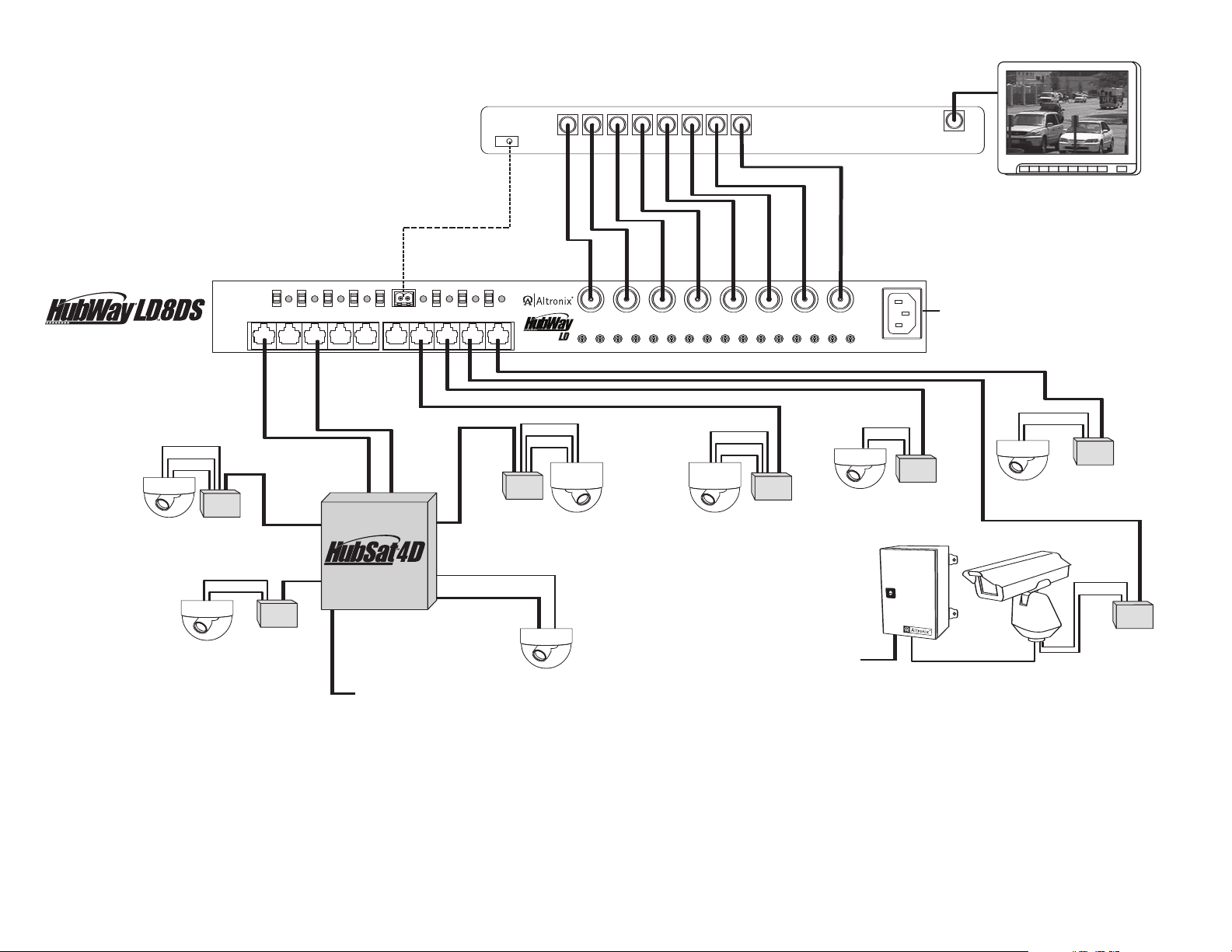
Note: When an installation exceeds the maximum distance for power transmission, a local external
er source is required. Optionally, an Altronix HubSat4D Passive UTP Transceiver Hub
w
po
w/Integral Power may be utilized (Fig
. 2, pgs. 2-3). The combined total cable distance betw
een the
HubWay, HubWayLD Series and each camera routed through the HubSat4D
must not exceed 3000 ft.
2. Measure the output voltage at each Video Balun/Combiner before connecting camera power
oid potential damage.
(Figs. 1a-1d, pg. 1). This helps a
v
• HubWayAv - Terminals marked [AC POWER] (Figs. 1a, 1b, pg. 1).
• HubWayDv/Dvi -
3. Connect the pow
Terminals marked [– 12VDC +] (Figs. 1c, 1d, pg. 1).
er outputs of the HubWayAv or HubWayDv Video Balun/Combiners to the power
input terminals of the cameras (Figs. 1a-1d, pg. 1).
4. Connect the terminals marked [+ DATA --] of the HubWayAv or HubWayDv Video Balun/Combiners
to the data ter
When using f
minals of the cameras for PTZ control (F
ixed cameras disregard this step (Figs. 2, pgs. 2-3).
5. Connect the BNC connector of the HubW
ayAv. HubWayDv or HubWayDvi Video Balun/Combiners
igs. 1a-1d, pg. 1). Polarity must be observed.
to the BNC video outputs of the cameras (Figs. 1a-1d, pg. 1).
Fig. 3 - CAT-5 Structured Cable Wiring Color Codes
HubWayAv, HubWayDv and HubWayDvi
Video Balun/Combiners
Overview:
HubWayAv, HubWayDv or HubWayDvi Video Balun/Combiners are UL Listed
accessories to be used with HubWay, HubWayLD and HubSat series. These Altronix
Passive and Active UTP Transceiver Hubs w/Integral Power route Video/Data and
Power from Altronix HubWay, HubWayLD and HubSat units for either 24VAC or 12VDC
fixed or PTZ indoor or outdoor cameras.
Note: Refer to HubWay series Rev. 032108, HubWayLD series Rev. 030408 or
HubSat series Re
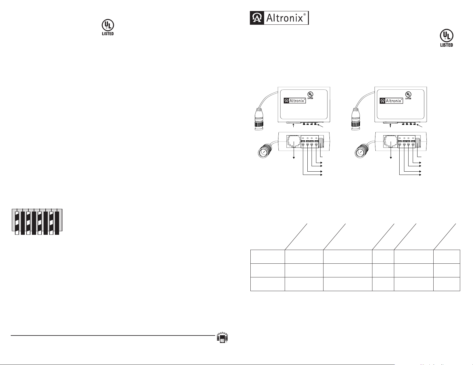
Fig. 1
Fig. 1a
Fig. 1b
HubWayAv passes AC voltage from pins 4, 5,
7, 8 to terminals marked [AC Power]
(Fig. 3, pg. 4).
v
. 112408 installation guides.
Fig. 1c
Fig. 1d
yDv/Dvi converts AC voltage to DC
HubWa
voltage from pins 4, 5, 7, 8 to terminals marked
[--12VDC +] (Fig. 3, pg. 4).
Video Balun/Combiner Reference Chart:
Altronix is not responsible for any typographical errors.
140 58th Street, Brooklyn, New York 11220 USA, 718-567-8181, fax: 718-567-9056
website: www.altronix.com, e-mail: info@altronix.com, Lifetime Warranty, Made in U.S.A.
IIHubWayVideo Balun/Combiners Rev. 123008 A16I
- 4 - HubWaAV/DV/Dvi
MEMBER
Altronix
Model Number
HubWayAv
HubWayDv
HubWayDvi
Input Voltage from
HubWay unit
to camera
Output Voltage
Output Ratings
*24VAC/28VAC *24VAC/28VAC 1 amp
*24VAC/28VAC 12VDC 1 amp
*24VAC/28VAC
12VDC electronically
isolated
.5 amp
(max.)
Camera Type
24VAC cameras
12VDC cameras
12VDC cameras
without isolation
Power LED
Green
Red
Red
*Based on camera load and structured cable length.
WARNING: To reduce the risk of fire or electric shock, do not expose the unit to rain or
moisture. This installation should be made by qualified service personnel and should conform to
all local codes.
HubWaAV/DV/Dvi - 1-
Page 2
Video
Data
Power
DC
Outdoor
NEMA Rated
Power
Supply
Head End
Equipment
(DVR)
RS485
Data
Video
Monitor
Outdoor
PTZ
Camera
115VAC Input, 60Hz
115VAC Input,
50/60Hz
Video
Power
Video
Data
Power
Video
Power
CAT-5
CAT-5
CAT-5
IEC 320 Connector
115VAC 60 Hz/230VAC
50/60 Hz.
Video (Coax)
Four (4) Video
signals on a
single CAT-5
Data
(CAT-5)
Power
HubWayAv
HubWayDv/Dvi
Video Balun
Combiner
Video
Data
Power
Video
Data
Power
CAT-5
CAT-5
Fixed
Camera
Fixed
Camera
Fixed
Camera
Video
Power
CAT-5
PTZ
Camera
PTZ
Camera
PTZ
Camera
CAT-5
24VAC/28VAC
Camera Power
Provided
by HubSat4D
Fixed
Camera
AC POWER
87654321
2
4VAC
OFF
28VAC
-
- DATA+
1
234
5678
C
H 1-4
C
H 5-8
1
-8
PICTURE GAIN PICTURE GAIN PICTURE GAIN PICTURE GAIN PICTURE GAIN PICTURE GAIN PICTURE GAIN PICTURE GAIN
HubWayAv
HubWayDv/Dvi
Video Balun
Combiner
HubWayAv
HubWayDv/Dvi
Video Balun
Combiner
HubWayAv
HubWayDv/Dvi
Video Balun
Combiner
HubWayAv
HubWayDv/Dvi
Video Balun
Combiner
HubWayAv
HubWayDv/Dvi
Video Balun
Combiner
HubWayAv
HubWayDv/Dvi
Video Balun
Combiner
Fig. 2
Typical Application Drawings:
HubWaAV/DV/Dvi - 3 -- 2 - HubWaAV/DV/Dvi
 Loading...