

Page 1

Video • Data • Power
Passive UTP Transceiver Hub
with Integral Camera Power
Installation Guide
Models Include:
HubSat4WP
- Four (4) Channel Outdoor Passive UTP Transceiver Hub with Integral Camera Power
HubSat42WP
- Four (4) Channel Outdoor Passive UTP Transceiver includes four (4) HubWayAv
Video Balun/Combiners
HubSat43WP
- Four (4) Channel Outdoor Passive UTP Transceiver includes four (4) HubWayDv
Video Balun/Combiners
Rev. 081809
More than just power.
TM
Page 2

Overview:
Altronix HubSat4WP Passive UTP Transceiver Hub w/Integral Camera Power transmits UTP video, RS422/RS485 data and
power over a single CAT-5 or higher structured cable. Unit provides 4 camera channels in a wall mount enclosure. Video
transmission range is up to 750 ft. max. per channel. Units are compatible with AC and/or DC fixed or PTZ cameras when
utilizing Altronix HubWayAv, HubWayAv2, HubWayDv or HubWayDvi Video Balun/Combiners. In addition, the unit features individually selectable 24VAC or 28VAC PTC protected outputs with surge suppression. Optionally, the HubSat4WP
can be used as an accessory module to transmit video from up to 4 cameras over a single CAT-5 or higher structured cables
back to the HubWay, HubWayLD or HubWayLDH Passive and Active UTP Transceiver Hubs. In addition, the HubSat4WP
provides power to these cameras locally to eliminate the possibility of voltage drop associated with long cable runs.
Specifica tions:
Input:
• 115VAC 60Hz, 1.25 amp.
Video:
• Four (4) channels of quality video over twisted pair
up to a distance of 750 ft. per channel.
• Four (4) 75 ohm video outputs.
Data:
• RS422/RS485 data input.
Power:
• Individually selectable 24VAC or 28VAC power
outputs with OFF position.
• Unit provides up to 1 amp max. per channel not to
exceed a total of 4 amp maximum current.
Power (cont’d):
• PTC protected outputs are rated @ 1 amp per channel.
• Surge suppression.
Visual Indicators:
• Four (4) power LED indicators.
Enclosure Dimensions (H x W x D approx.):
12” x 8” x 6” (304.8mm x 203.2mm x 152.4mm)
Optional Accessories:
• Video Balun/Combiners:
- HubWayAv - for use with 24VAC cameras.
- HubWayAv2 - for use with 24VAC cameras.
- HubWayDv - for use with 12VDC cameras.
- HubWayDvi - for use with non-isolated 12VDC cameras.
Additional Models:
HubSat42WP
• HubSat4WP with four (4) HubWayAv
Video Balun/Combiners for 24VAC Cameras.
HubSat43WP
• HubSat4WP with four (4) HubWayDv
Video Balun/Combiners for 12VDC Cameras.
Installation Instructions:
HubSat4WP Outdoor Passive UTP Transceiver Hub with Integral Camera Power.
Unit should be installed in accordance with The National Electrical Code and all applicable Local Regulations.
1. Remove back plate inside the enclosure by removing the four (4) mounting screws (Fig. 4, pg. 6).
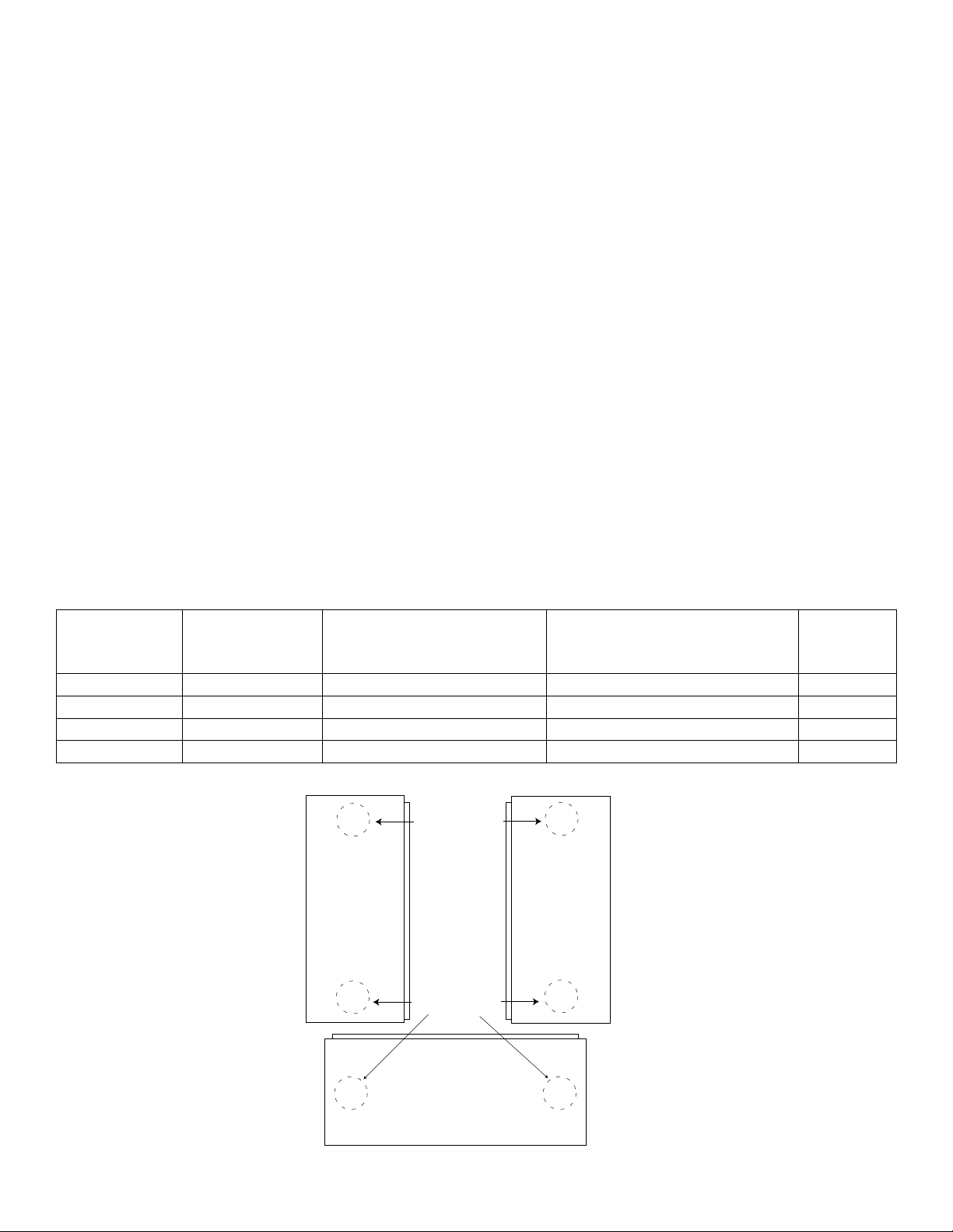
2. Mark and drill desired knockouts on the enclosure to facilitate wiring (Fig. 1, pg. 4).
3. Secure back plate inside the enclosure with the four (4) mounting screws (Fig. 4b, pg. 6).
4. Unit can be wall or pole mounted.
Wall Mount:
- Mark and drill holes to line up with the top and bottom holes of the enclosure flange.
- Secure enclosure with appropriate fasteners (Enclosure Dimensions, pg. 12).
Pole Mount:
- Refer to the detailed pole mount instructions (pg. 9).
Secure enclosure to earth ground.
4. Set illuminated master power disconnect circuit breaker to the (OFF) position (Fig. 4a, pg. 6).
5. Connect 115VAC 60Hz to the black and white flying leads of open frame transformer. Secure ground
wire (Green) to earth ground (Fig. 4, pg. 6).
6. S elect 24VAC or 28VAC power output for each of the Channels 1-4 on HubSat4WP (Fig. 4, pg. 6) with the
corresponding output voltage switches. Select OFF position when servicing or installing individual
cameras (Fig. 2d, pg. 5).
7. Connect the BNC video outputs marked [Video 1-4] on HubSat4WP to the corresponding video inputs on the
head end equipment (DVR) (Fig. 2a, pg. 5).
8. Connect terminals marked [+ Data --- ] on HubSat4WP (polarity must be observed) to the RS422/RS485 output
of the head end equipment (DVR) (Fig. 2f, pg. 5). When using fixed cameras disregard this step.
9. Plug the RJ45 connector at one end of the CAT-5 or higher structured cable into the RJ45 jack marked [PVD1]
on HubSat4WP (Fig. 2i, pg. 5). Plug the RJ45 connector at the opposite end of the CAT-5 or higher structured
cable into the RJ45 jack of the Video Balun/Combiner to be installed at camera 1.
• For 24VAC cameras use Altronix model HubWayAv/HubWayAv2 Video Balun/Combiner (Figs. 3a, 3b, pg. 6).
• For 12VDC cameras use Altronix model HubWayDv Video Balun/Combiner (Figs. 3c, 3d, pg. 6).
• For non-isolated 12VDC cameras use Altronix model HubWayDvi Video Balun/Combiner (Figs. 3c, 3d, pg. 6).
The total cable distance must not exceed 750 ft. for video transmission between the HubSat4WP and each camera.
- 2 - HubSat4WP
Repeat this step for all other camera channels [PVD2-4].
Page 3

10. Set illuminated master power disconnect circuit breaker to the RESET (ON) position (Fig. 4a, pg. 6). Power LEDs
(Green) of the HubSat4WP will illuminate when AC power is present (Fig. 2e, pg. 5) and HubWayAv, HubWayDv or
HubWayDvi Video Balun/Combiner LEDs will illuminate indicating power is present (Fig. 3b, 3d, pg. 5).
11. Measure the output voltage at each Video Balun/Combiner (Figs. 3b, 3d, pg. 5) before making connections to
each camera to ensure proper operation and avoid possible damage.
12. Set illuminated master power disconnect circuit breaker to the (OFF) position (Fig. 4a, pg. 6).
13. Connect power outputs of HubWayAv, HubWayAv2, HubWayDv or HubWayDvi Video Balun/Combiners to power
inputs of cameras (Figs. 3a-3d, pg. 6). Polarity must be observed.
• HubWayAv/HubWayAv2 - Terminals marked [AC POWER] (Figs. 3a, 3b, 3e, pg. 5).
• HubWayDv/HubWayDvi - Terminals marked [– 12VDC +] (Figs. 3c, 3d, pg. 5).
14. Connect the terminals marked [+ DATA -- ] of HubWayAv, HubWayAv2, HubWayDv or HubWayDvi Video Balun/
Combiners to data input terminals of cameras for PTZ control (Figs. 3a-3e, pg. 5). Polarity must be observed.
When using fixed cameras disregard this step.
15. Connect the BNC connector of HubWayAv, HubWayAv2, HubWayDv or HubWayDvi Video Balun/Combiners to
the BNC video outputs of cameras (Figs. 3a-3e, pg. 5).
16. Set illuminated master power disconnect circuit breaker to the RESET (ON) position (Fig. 4a, pg. 6).
17. The power LEDs (Green) of the HubSat4WP will illuminate when AC power is present (Fig. 2e, pg. 5).
Note: If any of the power LEDs are not illuminated the cause may be due to the following:
a. AC mains fail.
b. Illuminated master power disconnect circuit breaker is tripped.
c. An individual power output voltage switch is set to the OFF position (Fig. 2d, pg. 5).
d. A PTC is tripped due to a short circuit or overload condition for one or more channels/power outputs.
To reset the PTC:
1. Set the voltage output selector switch for that corresponding channel to the OFF position. Switch must
remain in the OFF position for approximately 2 minutes in order for the PTC to reset (Fig. 2d, pg. 5).
2. Eliminate the trouble condition (short circuit or overload).
3. Set the voltage output selector switch for either 24VAC or 28VAC (Fig. 2d, pg. 5).
HubSat4WP for use as a Remote Accessory Module with HubWay/HubWayLD/HubWayLDH UTP Transceiver Hubs.
After completing steps 1-4 of Installation Instructions for HubSat4WP Outdoor Passive UTP Transceiver Hub with
Integral Camera Power proceed with the following.
1. For fixed cameras run a single CAT-5 cable between HubSat4WP and HubWay, HubWayLD or HubWayLDH
to allow video transmission of up to four (4) cameras. For PTZs run two (2) CAT-5 cables between HubSat4WP
and HubWay, HubWayLD or HubWayLDH (Fig. 6, pg. 7).
a. Connect one (1) of the CAT-5 cables to the RJ45 jack marked [Video 1-4] on HubSat4WP. Connect the
opposite end of this CAT-5 cable into the RJ45 jack marked [CH 1-4] of HubWay, HubWayLD or
HubWayLDH unit (Fig. 6, pg. 7).
b. For data (PTZ) connect the second CAT-5 cable to the RJ45 jack marked [Data 1-4] on HubSat4WP. Connect
the opposite end of this CAT-5 cable into any unused RJ45 jack marked [1-16] of HubWay, HubWayLD or
HubWayLDH unit (Fig. 6, pg. 7).
Note: Data inputs of HubWay, HubWayLD or HubWayLDH units must be wired in parallel for proper operation.
When using fixed cameras disregard this step.
2. Plug the RJ45 connector at one end of the CAT-5 or higher structured cable into the RJ45 jack marked [PVD1]
on HubSat (Fig. 2i, pg. 4). Plug the RJ45 connector at the opposite end of the CAT-5 or higher structured
cable into the RJ45 jack of the Video Balun/Combiner to be installed at camera 1.
• For 24VAC cameras use Altronix model HubWayAv/HubWayAv2 Video Balun/Combiner (Figs. 3a, 3b, 3e, pg. 5).
• For 12VDC cameras use Altronix model HubWayDv Video Balun/Combiner (Figs. 3c, 3d, pg. 5).
• For non-isolated 12VDC cameras use Altronix model HubWayDvi Video Balun/Combiner (Figs. 3c, 3d, pg. 5).
The total cable distance must not exceed 750 ft. for video transmission between the HubSat4WP and each camera.
Repeat this step for all other camera channels [PVD2-4].
3. Set illuminated master power disconnect circuit breaker to the RESET (ON) position (Fig. 4a, pg. 6). Power LEDs
(Green) of the HubSat4WP will illuminate when AC power is present (Fig. 2e, pg. 5) and HubWayAv, HubWayDv
or HubWayDvi Video Balun/Combiner LEDs will illuminate indicating power is present (Fig. 3b, 3d, pg. 5).
4. Measure the output voltage at each Video Balun/Combiner (Figs. 3b, 3d, 3e, pg. 5) before making connections to
each camera to ensure proper operation and avoid possible damage.
5. Set illuminated master power disconnect circuit breaker to the (OFF) position (Fig. 4a, pg. 6).
6. Connect power outputs of HubWayAv, HubWayAv2, HubWayDv or HubWayDvi Video Balun/Combiners to power
inputs of cameras (Figs. 3a-2e, pg. 5). Polarity must be observed.
• HubWayAv/HubWayAv2 - Terminals marked [AC POWER] (Figs. 3a, 3b, pg. 5).
• HubWayDv/HubWayDvi - Terminals marked [– 12VDC +] (Figs. 3c, 3d, pg. 5).
HubSat4WP - 3 -
Page 4
7. Connect the terminals marked [+ DATA -- ] of HubWayAv, HubWayAv2, HubWayDv or HubWayDvi Video
Right PanelLeft Panel
Balun/Combiners to data input terminals of cameras for PTZ control (Figs. 3a-3e, pg. 5). Polarity must be observed.
When using fixed cameras disregard this step.
8. Connect the BNC connector of HubWayAv, HubWayAv2, HubWayDv or HubWayDvi Video Balun/Combiners to
the BNC video outputs of cameras (Figs. 3a-3e, pg. 5).
9. Set illuminated master power disconnect circuit breaker to the RESET (ON) position (Fig. 4a, pg. 6).
10. The power LEDs (Green) of the HubSat4WP will illuminate when AC power is present (Fig. 2e, pg. 5).
Note: If any of the power LEDs are not illuminated the cause may be due to the following:
a. AC mains fail.
b. Illuminated master power disconnect circuit breaker is tripped.
c. An individual power output voltage switch is set to the OFF position (Fig. 2d, pg. 5).
d. A PTC is tripped due to a short circuit or overload condition for one or more channels/power outputs.
To reset the PTC:
1. Set the voltage output selector switch for that corresponding channel to the OFF position. Switch must
remain in the OFF position for approximately 2 minutes in order for the PTC to reset (Fig. 2d, pg. 5).
2. Eliminate the trouble condition (short circuit or overload).
3. Set the voltage output selector switch for either 24VAC or 28VAC (Fig. 2d, pg. 5).
Alternate 24VAC fixed camera hookup (Fig. 6a, pg. 7).
After completing steps 1-5 of Installation Instructions Remote Accessory Module for use with HubWay, HubWayLD or
HubWayLDH UTP Transceiver Hubs proceed with the following.
1. Set illuminated master power disconnect circuit breaker to the (OFF) position (Fig. 4a, pg. 6).
2. Connect one end of the coaxial cable to the BNC connector marked [Video1] on HubSat4WP (Fig. 2a, pg. 5).
Connect the opposite end of the coaxial cable to the BNC video output of camera 1 (Fig. 6a, pg. 7).
3. Set illuminated master power disconnect circuit breaker to the RESET (ON) position (Fig. 4a, pg. 6) measure the
output voltage at terminal pair marked [AUX1] on HubSat4WP to insure proper operation and avoid possible
damage (Fig. 2b, pg. 5).
4. Connect the power output terminal pair marked [AUX1] on HubSat4WP to the power inputs of camera 1
(Fig. 2c, pg. 5). Repeat steps 1-3 for each additional camera [AUX2-4].
HubWayAv, HubWayAv2, HubWayDv, and HubWayDvi Video Balun/Combiners:
Input Voltage
Altronix
Model Number
HubWayAv
HubWayAv2
HubWayDv
HubWayDvi
*Based on camera load and structured cable length.
from HubWay
Unit Output Voltage to Camera Camera Type Power LED
*24VAC/28VAC *24VAC/28VAC *24VAC/28VAC Green
*24VAC/28VAC *24VAC/28VAC *24VAC/28VAC N/A
*24VAC/28VAC 12VDC
*24VAC/28VAC 12VDC electronically isolated 12VDC cameras without isolation Red
Fig. 1
Suggested Locations
for Wire Entries
Suggested Locations
for Wire Entries
12VDC cameras
Red
- 4 - HubSat4WP
Bottom Panel
Page 5

Fig. 2 - HubSat Circuit Board
2b
28VAC
2c
AUX1 AUX2 AUX3 AUX4
28VAC
28VAC
2c
2d
28VAC
OFF
24VAC
VIDEO1 VIDEO2 VIDEO3 VIDEO4
24VAC
OFF
24VAC
2a
2i
PVD1
2a - BNC Connector: Video in from remote camera
video out to DVR.
2b - Output PTCs: Protects each output.
2c - Power Terminals: 24VAC/28VAC power outputs.
2d - Output Voltage Switches: Selects 24VAC/28VAC/
OFF for each output.
2e - LED(s) 1-4: Power output indicators.
2f - Data: RS422/RS485 input from head end equipment
PVD2 PVD3 PVD4
DATA 1-4 VIDEO 1-4
2g - Channels 1-4: Single CAT-5 or higher structured
cable out to HubWay, HubWayLD or HubWayLDH
enables transmission of up to four (4) video signals.
2h - Data: CAT-5 or higher structured cable to data port
on HubWay, HubWayLD or HubWayLDH or head
end equipment (DVR).
2i - Channels 1-4: CAT-5 or higher structured cable
to cameras.
(DVR) for PTZ control.
Fig. 3 - HubWayAv and HubWayDv/Dvi Video Balun/Combiners
Fig. 3a
VIDEO
Fig. 3c
HubWayAv
VIDEO BALUN/COMBINER
CAT5 + DATA-- POWER
AC
OFF
2g2h
VIDEO
HubWayDv
VIDEO BALUN/COMBINER
CAT5 + DATA-- -- 12VDC+
24VAC
OFF
2e
2f
+ DATA -
* Also Available as:
HubWayDvi
Video Balun/
Combiner
for non-isolated
12VDC cameras
Wire
RJ45 Jack RJ45 Jack
Connectors
Wire
Connectors
Fig. 3b Fig. 3d
To BNC
Connector
of Camera
Structured
Cable from
HubSat4WP
Green Power LED
AC Power
to Camera
--
Data to
Camera
+
Fig. 3e
HubWayAv2
Cat5
back to
HubWay
or
HubSat
HubWayAv/HubWayAv2 passes AC voltage from pins
4, 5, 7, 8 to terminals marked [AC Power] (Fig. 3, pg. 5).
To BNC
Connector
of Camera
Power to Camera
Data to Camera
Video from Camera
Structured
Cable from
HubSat4WP
HubWayDv/HubWayDvi converts AC voltage to DC
voltage from pins 4, 5, 7, 8 to terminals marked
Red Power LED
+
12VDC Power
to Camera
--
--
Data to
Camera
+
[-- 12VDC +] (Fig. 3, pg. 5).
HubSat4WP - 5 -
Page 6

CAT-5 Structured Cable Wiring Color Codes and PIN Configurations
1 - White/Orange [VIDEO +]
2 - Orange [VIDEO -- ]
3 - White/Green [DATA +]
4 - Blue [AC 1]
5 - White/Blue [AC 2]
6 - Green [DATA -- ]
7 - White/Brown [AC 2]
8 - Brown [AC 1]
Fig. 4 Fig. 4b
(ON)
Fig. 4a
Illuminated master power
disconnect circuit breaker:
• OFF position:
Circuit breaker tripped –
Switch not illuminated.
• RESET (ON) position:
Switch illuminated.
28VAC
24VAC
VIDEO1 VIDEO2VIDEO3VIDEO4
PVD1
AUX1 AUX2
OFF
PVD2 PVD3 PVD4
28VAC
28VAC
OFF
24VAC
24VAC
DATA 1-4VIDEO 1-4
OFF
AUX3 AUX4
28VAC
24VAC
non power-limited
Black
Lead
White
Lead
XFMR
115VAC 60 Hz Input
non power-limited
OFF
0 (Br)
BK
24(YL)
+ DATA -
Green Lead
(Ground)
- 6 - HubSat4WP
Page 7

Head End Equipment (DVR)
Fig. 5
Fig. 6
Typical Application Drawing
HubSat4WP Passive UTP Transceiver Hub with Integral Camera Power:
Monitor
RS485
Data
Data
Power
12VDC PTZ
Camera
Data
Video
12VDC Fixed
Camera
CAT-5
HubWayDv/Dvi
Video Balun
Combiner
Video
Power
CAT-5
HubWayDv/Dvi
Video Balun
Combiner
BNC
115VAC Input,
60Hz
CAT-5
HubWayAv
Video Balun
Combiner
24VAC/28VAC
Camera Power
Provided
by HubSat4WP
Video
Power
CAT-5
HubWayAv
Video Balun
Combiner
24VAC PTZ
Camera
Video
Power
24VAC Fixed
Camera
Typical Application Drawing
HubSat4WP Remote Accessory Module with HubWay UTP Transceiver Hubs:
Head End Equipment (DVR)
Rear
Data
Video
Power
HubWayDv/Dvi
Video Balun
12VDC
Camera
PTZ
12VDC
Camera
Fixed
Combiner
Video
Power
HubWayDv/Dvi
Video Balun
Combiner
RS485
Data
1234CH 1-4 CH 5-8
Data
(CAT-5)
CAT-5
CAT-5
24VAC/28VAC
Camera Power
Provided
by HubSat4WP
115VAC
Input, 60Hz
5678
+ DATA -
1-8
Four (4) Video
signals on a
single CAT-5
CAT-5
HubWayAv
Video Balun
Combiner
CAT-5
HubWayAv
Video Balun
Combiner
28VAC
OFF
24VAC
Data
Video
Power
Video
Power
Video
87654321
PICTURE GAIN PICTURE GAIN PICTURE GAIN PICTURE GAIN PICTURE GAIN PICTURE GAIN PICTURE GAIN PICTURE
Monitor
Four (4) Video
signals on a
single CAT-5
Power
Video (Coax)
24VAC
PTZ
Camera
24VAC
Fixed
Camera
Power
Video (Coax)
24VAC
Fixed
Camera
24VAC
Fixed
Camera
24VAC/28VAC
Camera Power
Provided
by HubSat4WP
115VAC
Input, 60Hz
AC POWER
GAIN
Power
Video (Coax)
Power
Video (Coax)
Front
24VAC
Fixed
Camera
24VAC
Fixed
Camera
Fig. 6a - Alternate 24VAC fixed camera hookup.
HubSat4WP - 7 -
Page 8

The lightning flash with arrow head symbol within an equilateral triangle is intended to alert the user to the
presence of an insulated DANGEROUS VOLTAGE within the product’s enclosure that may be of sufficient
magnitude to constitute an electric shock.
The exclamation point within an equilateral triangle is intended to alert the user to the presence of important
operating and maintenance (servicing) instructions in the literature accompanying the appliance.
CAUTION: To reduce the risk of electric shock do not open enclosure. There
are no user serviceable parts inside. Refer servicing to qualified service personnel.
Wall Mount Installation
1. Place unit at the desired location and secure with mounting screws (not included) (Fig. 7 and Fig. 7a, pg. 8).
Fig. 7
Fig. 7a
- 8 - HubSat4WP
Page 9

Pole Mounting Using Optional Pole Mount Kit PMK1 (not included):
This installation should be made by qualified service personnel. This product contains no serviceable parts. PMK1 is intended for use with Altronix outdoor rated power supplies or accessories housed in WP1, WP2, WP3 and WP4 enclosures.
Brackets are designed for use with the Wormgear Quick Release Straps (two included).
1. Thread one (1) wormgear quick release strap through the slots on the back of a mounting bracket (Fig. 8, pg. 9).
2. Once the desired height of the top Pole Mount bracket is achieved, tighten the straps down by sliding open end
of the strap through the locking mechanism on the strap, then tighten the screw with
flat head screwdriver or 5/16” hex socket driver (Fig. 8a, pg. 8 and Fig. 8b, pg. 8).
Fig. 8
Fig. 8a
3. Attach the bottom bracket to the enclosure by inserting bolts through the
flange of the enclosure and into the bracket, tightening bolts with a
7/16” hex socket (Fig. 8c, pg. 9).
4. Thread the second wormgear quick release strap through the slots on the
back of the bottom mounting bracket (Fig. 8, pg. 9).
5. Mount enclosure onto the top bracket by inserting bolts through
flange of the enclosure and into the bracket,
tightening bolts with a 7/16” hex socket (Fig. 8a, pg. 9).
6. Tighten the straps of the bottom bracket down by sliding the open end of
the strap through the locking mechanism on the strap, then tighten screw
with flat head screwdriver or 5/16” hex socket driver (Fig. 8d/8e, pg. 9).
7. Clip excess straps.
Fig. 8b
Fig. 8c
Fig. 8d - 2” to 8”(50.8mm to 203.2mm) Fig. 8e - 5” (127mm) square pole
diameter round pole
- 9 - HubSat4DWP
Page 10

Notes:
- 10 - HubSat4DWP
Page 11

Notes:
- 11 - HubSat4DWP
Page 12
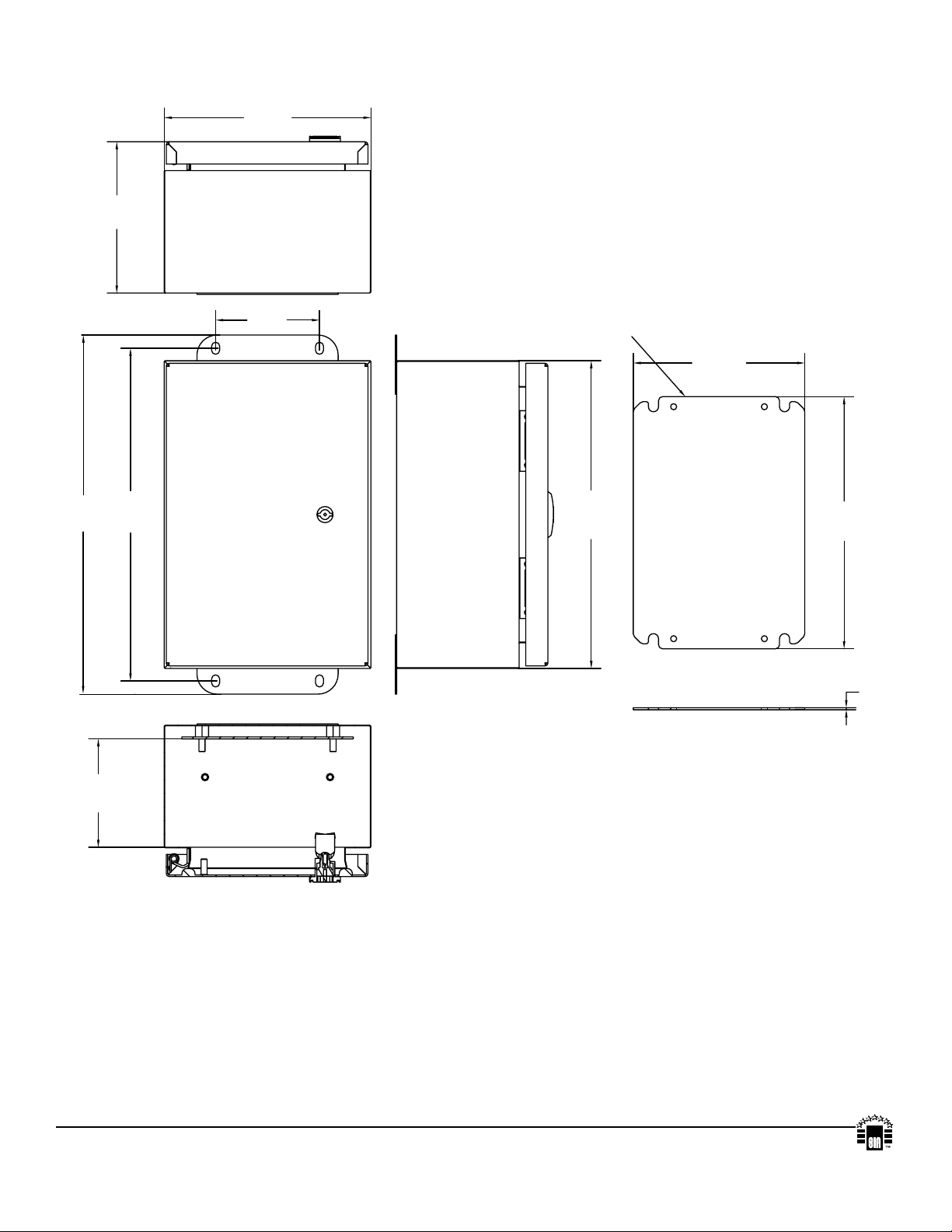
6”
355.6m
152.4mm
Enclosure Dimensions (H x W x D approximate):
12” x 8” x 6” (304.8mm x 203.2mm x 152.4mm)
8”
203.2mm
14”
m
13”
330mm
4.05”
103mm
MOUNTING PANEL
GALVANIZED
12”
305mm
6.7”
170mm
9.84”
250mm
0.08”
2mm
CARBON STEEL SHEET
4.21”
107mm
Altronix is not responsible for any typographical errors.
140 58th Street, Brooklyn, New York 11220 USA, 718-567-8181, fax: 718-567-9056
website: www.altronix.com, e-mail: info@altronix.com, Lifetime Warranty, Made in U.S.A.
- 12 - HubSat4DWP
IIHubSat4WP B25O
MEMBER
 Loading...