

Page 1

AT4/AT4B
Annual Event Timer
Installation Guide
Rev. 110805
Page 2

AT4/AT4B - Annual Event Timer
Overview:
These units are extremely versatile 24 Hour 365 Day Event Timers designed to support a wide range of applications.
Such applications include: Home and Building Automation, Security, Access Control, Lighting Control, Etc.
AT4/AT4B is equipped with four independently controlled form “C” relay contacts that provide many latching and/or
momentary operations during a program schedule of your choice. The EE prom memory allows for programming of unit
prior to/or during field installation. Events may be set for single or multiple operations on a daily and/or weekly
schedule. The block programming feature enables repeating an event on any combination of consecutive days. AT4/AT4B
will compensate for daylight savings time if desired. It automatically adjusts for leap year. Individually selected holiday
exceptions can be programmed to over-ride regularly scheduled events.
Specifications:
• 12 to 24 volts AC or DC operation.
• Stand-by current: 20mA with relays off combined with 40mA for each relay on.
• Four (4) Form “C” relay contacts are rated 10amp @120VAC/28VDC.
• Each relay operates independently.
EE Prom memory protects against loss of programming due to power failure.
•
• Accurate crystal controlled clock.
• Momentary and/or Latching Events.
• 254 individually pro
• Block programming capacity can accommodate a total of 1778 events per week.
• 254 pro
• “First man in” option.
• Alphanumeric LCD display simplifies programming.
• Standard or Daylight Sa
• Automatic compensation for leap year.
• Built-in charger for 12VDC sealed lead acid or gel type batteries
(Max char
• Lithium battery backup maintains clock (Altronix part # LB2032).
• User friendly programming.
Enclosure dimensions: 12.25”H x 7.75”W x 4.5”D
AT4B board level product. Board dimensions (approximate): 7”H x 5.5”W x 1.2”D
grammable Holiday events.
ge current 300mA).
grammed daily/weekly events.
vings Time settings.
Installation Instructions:
1. Mount AT4 enclosure in desired location.
Carefully Review:
Basic Oper
erminal Identif
T
Keyboard Layout and Description (pg. 4)
Programming Instructions (pgs. 4-6)
2. Connect 12 to 24 Volts AC or DC to terminals marked [-DC+]. (when using DC carefully observe polarity).
3. Connect 12VDC battery (optional) to terminals marked [BAT-] and [BAT+] .
4. Insert lithium battery (not supplied or required. Altronix part# LB2032) in battery holder as shown in
ith the (+) positi
W
Note: Lithium Battery (LB2032) must only be installed after initial power up of AT4/AT4B.
5. Connect de
Note: It is impor
Strikes, Bells, Relays, etc. to install a catch diode across the pos (+) and neg (-) terminals of the device.
Connect diode as close to the device as possible with the banded side facing the pos (+) terminal. This will
reduce the possibility of interference.
6. Program clock and desired event schedule (
ation
able (pg. 3)
ication
vices to be controlled to dry outputs marked RLY1 [NC, NO, C] - RLY4 [NC, NO, C]
tant w
T
e side f
v
acing up.
hen connecting DC po
(pg. 3)
(Fig. 1, pg. 4).
wered electromechanical devices such as Mag Locks, Electric
Programming Instructions pg. 4-6).
- 2 -
Page 3
Basic Operation:
SET CLOCK NOW!
01/01/05 SU 00:00 DS
AT4/AT4B controls four (4) independently operated dry form “C”relay outputs. Relays, can be programmed to: turn on
(latch), turn off (latch) or pulse (toggle) at a specified time and day (this is referred to as an event). Events are prog
rammed via the keyboard and LCD display. These events can be designated to operate any one of the four (4) relays
independently. Relay 1 corresponds to RL01, Relay 2 corresponds to RL02, etc. on the display.
Events may be programmed to occur on any day of the week at any time. In addition, events may be repeated at a
specific time on two (2) or more consecutive days (i.e. M-F, Sun-Th, etc) Multiple combinations of individual and block
events may be programmed. Holiday exceptions are individually selected by date and will over-ride all regularly
scheduled events.
The four (4) output relay modes consist of:
Relay OFF - De-energizes the relay(s) selected until a relay On event is detected
Relay ON - Energizes the relay(s) selected until a Relay OFF event is detected.
Disable - Used to cancel and existing programmed event.
Pulse - Momentarily energizes the relay(s) for a selectable time period of 1 sec. to 15 sec
Output relays are designated by the following:
RL01 = Relay 1, RL02 = Relay 2, RL03 = Relay 3, RL04 = Relay 4
Time is displayed in 24 hr military format.
Terminal Identification:
Terminal Legend Function/Description
RLY1: NC, NO, C
RLY2: NC, NO, C
RLY3: C, NC, NO
Dry Contact output used to switch controlled de
When these relays are energized (On) the NC and C terminals are open and
the NO and C terminals are closed. When these relays are de-energized (Off)
the NC and C terminals are closed and the NO and C ter
vices.
minals are open.
RLY4: C, NC, NO
- DC + AC or DC Input 12 to 24 volt. When using DC carefully observe polarity.
- BAT+ 12VDC stand-by battery input (battery leads provided).
FM When this terminal is connected to DC neg. (-) the “First Man in” feature is enabled.
All rela
At that time rela
ys will remain in their present position until this connection is terminated.
ys will resume nor
mal operation and latest scheduled events will occur
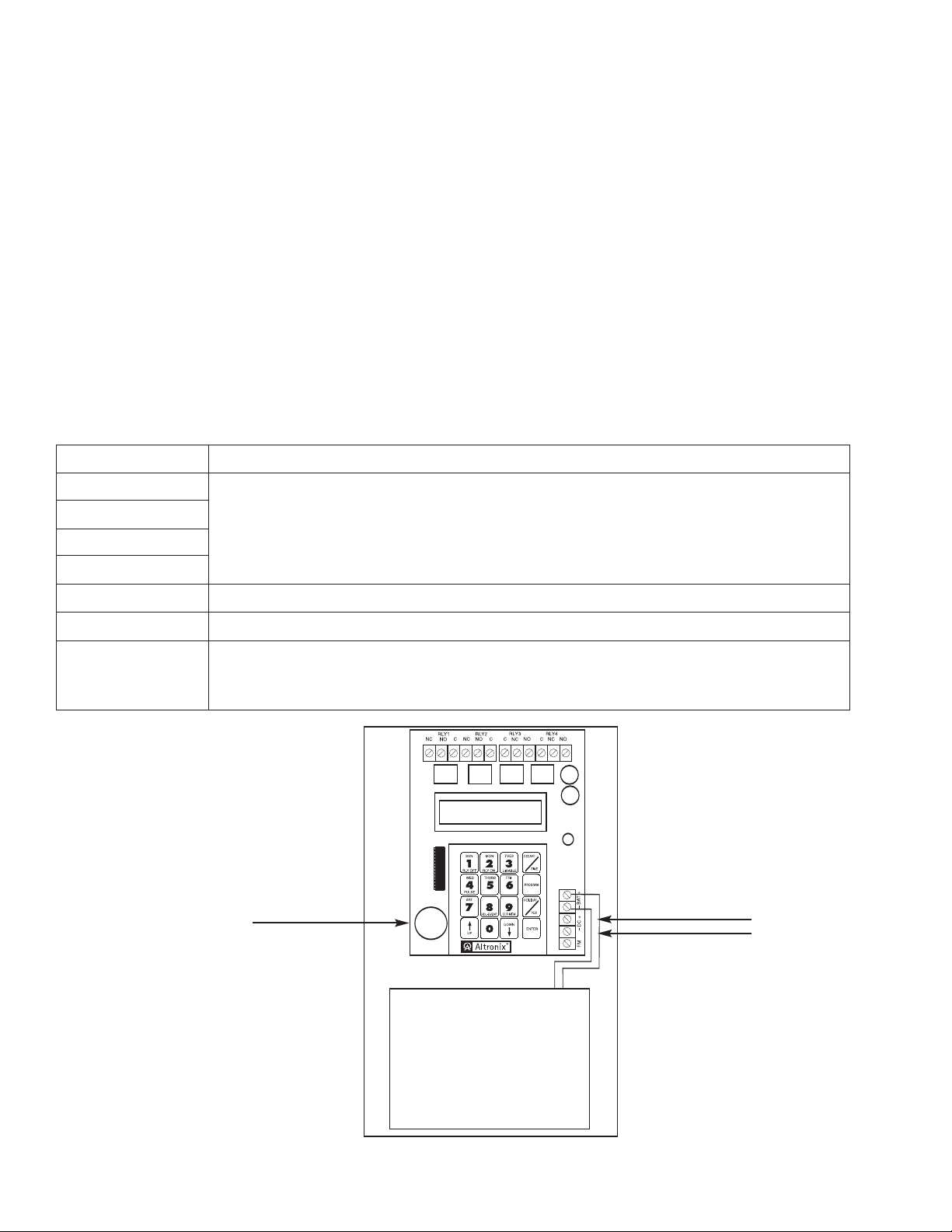
Fig. 1
Lithium Battery Socket
(Altronix part # LB2032)
12-24 Volt
AC/DC input
12VDC
Rechargeable Battery
- 3 -
Page 4

Keyboard Layout:
Keyboard Description:
Key Function/Description
1 Selects Sundays, Relay Off or numeral one (1)
2 Selects Monday, Relay On or numeral two (2)
3 Selects Tuesday, Relay Disable or numeral three (3)
4 Selects Wednesday, Relay Pulse or numeral four (4)
5 Selects
6 Selects F
7 Selects Saturda
8 Selects Holida
9 Clears entire programmed memory or selects numeral 9
0 Selects numeral 0
wn
Up/Do
Escape/T
Program Enables event programming.
Holiday/Yes Enables holiday event selection. Confirms request to clear all
Enter Advances cursor when in programming mode.
Note: Most keys are multi-functional and will be used to input different information depending
on the mode AT4/AT4B is in.
ime Backspaces cursor w
and
UP
ENTER to accept.
Scrolling k
exit all program modes.
previously programmed events.
WN
DO
Thursday or numeral five (5)
riday or numeral six (6)
y or numeral seven (7)
ent or numeral 8
y Ev
eys for programming
hen in pro
ys can be used to select data entries. After scrolling to the correct entry, depress
e
k
gramming mode, enables clock set mode,
Programming Instructions:
A. Setting Clock/Calendar:
Upon initial po
Enter today’s date, present day of the week, current time (24 hr. military format) by depressing number keys.
Note: The flashing cursor denotes location of data entry selection to be made. If an entry was made in error
or requires changing, depress either
w select either DS (da
No
depressing UP followed by ENTER.
wer up SET CLOCK NOW!
01/01/98 SU 00:00 DS
ESCAPE to backspace, or ENTER to accept data and advance the cursor.
ylight savings mode) by depressing DOWN or ST (standard time mode) by
will appear in displa
- 4 -
.
y
Page 5

Example: To program 02/14/99 SU 10:25 am DS (daylight savings) depress the following sequence of keys:
DOWN
ENTER
To change or reprogram clock/calendar depress TIME and make new selections by repeating steps above.
B. Setting Events:
Depress PROGRAM once. EVNT #0001^RL01 SU/SU
will appear in display.
RLY 00:00
Depress ENTER until the flashing cursor reaches the RL01 display location. Select
the output relay (RLY1 through RLY4) desired by depressing 1 through 4.
Next, select the day of week by depressing SUN through SAT. If this event is to occur on only one
specific day, repeat the previous entry again.
Note: When it is required to have the same event repeated on two (2) or more consecutive days of the week
(Block Programming), enter the first day followed by the last day by depressing SUN through SAT.
Example:
1) Monday through Thursday depress MON followed by THURS.
2) Wednesday through Sunday depress WED followed SUN.
Next select type of e
vent required:
Depress RLY OFF for Relay OFF (Latching Mode)
Depress RLY ON for Relay ON (Latching Mode)
Depress PULSE for Relay PLS (Pulse/Toggle Mode)
When selecting Pulse/Toggle Mode it is necessar
y to assign the length of time (duration) of relay activation.
The pulse can range in length from 1 second minimum to 15 seconds maximum by depressing the number
keys 0 through 9.
Note: If pulse duration is not selected relay output defaults to 1 second.
Next select the time (military format) of day(s) event should occur by depressing the number
keys 0 through 9. Depress ENTER to accept. Display automatically scrolls to the next event number to be
grammed. You ma
pro
y continue to enter events by repeating the previous steps or exit programming
by depressing ESCAPE.
Note: When programming additional events it is necessary to select the next consecutive event number
following the last event programmed to continue.
Example: To program event #1 to cause Relay 2 to Toggle/Pulse for five (5) seconds on both Sat. and Sun.
at 11:59 pm, depress the following sequence of keys:
C.1 Setting Holiday Events:
Depress
OGRAM
PR
once. Select the ne
xt available event number by depressing keys 0 through 9.
Depress ENTER until the flashing cursor reaches the RL01 display location. Select the output relay
(RLY01 through RLY04) desired by depressing 1 through 4. Next depress HOL-EVENT.
HL/HL will appear in the display designating this event as a holiday.
ent required:
xt select type of e
Ne
v
Depress RLY OFF for Relay OFF (Latching Mode)
Depress RL
ON for Rela
Y
y ON (Latching Mode)
Depress PULSE for Relay PLS (Pulse/Toggle Mode)
When selecting the Pulse/Toggle mode it is necessary to assign the length of time (duration) of relay
activation. The pulse can range in length from 1 second minimum to 15 seconds maximum by depressing the
number keys 0 through 9.
- 5 -
Page 6

Note: If pulse duration is not selected relay output defaults to 1 second.
N
ext select the time (military format) of holiday event should occur by depressing the number keys 0
through 9. Depress ENTER to accept. Display automatically scrolls to the next event number to be
programmed. You may continue to enter holiday events by repeating the previous steps or exit
programming by depressing ESCAPE.
Example: To program holiday event #2 to cause Relay 2 to Latch (Relay On) at 08:00 am depress the
following sequence of keys:
Note: Holiday events will always override any regularly scheduled events.
C.2 Setting Holiday Dates:
It is now necessary to assign these holiday events specific calendar dates which they are to occur. To set
holiday event dates depress HOLIDAY/YES once HOL #0001 01/01/01 will appear in display.
Depress ENTER until the flashing cursor reaches the date display location. Next make your selection by
depressing the number keys 0 through 9. You may continue to add holiday event dates by repeating the
previous steps or exit programming by depressing ESCAPE.
Example: To program holiday events to occur on Dec. 25, 2000 depress the following sequence of keys:
You may continue to program the next holiday date or depress ESCAPE to exit.
Delete/Disable Events or Edit Events:
D.
Previously pro
erase all events. To proceed depress
keys 0 through 9. When cursor is flashing under
depressing UP you can scroll through all the events programmed. If any event needs to be modified or disabled
depress ENTER. Ne
DISABLE and RL
accept modification. Repeat the previous steps above to locate and disable other events or depress ESCAPE
to exit.
.
Pre
viously programmed regular and/or Holiday events may be edited by depressing PROGRAM once.
Locate the event number by depressing the number keys 0 through 9 or scroll using the UP key. Proceed
to mak
Delete
E.
All previously programmed events can be deleted by simply depressing CLR MEM.
deletion.
e any changes (i.e. RL#, Day, Relay Event Type, Time) and depress ESCAPE to exit.
All Ev
CLEAR
grammed regularly scheduled and/or holiday events may be deleted/disabled without having to
PROGRAM once. Locate the event number by depressing the number
^ symbol in display, scrolling feature is activated. By
xt, depress ENTER until flashing cursor reaches the RLY display location. Depress
Y DIS will appear in display. Depress ENTER until the next event number appears to
ents:
ALL EVENTS? will appear in display. Accept by depressing YES followed by 1 to confirm
- 6 -
Page 7

Customer Event Log
E
vent # Relay # Day/Block Holiday Dates Event Type
- 7 -
Page 8

Customer Event Log
Event # Relay # Day/Block Holiday Dates Event Type
Altronix is not responsible for any typographical errors. Product specifications are subject to change without notice.
140 58th Street, Brooklyn, New York 11220 USA, 718-567-8181, fax: 718-567-9056
ebsite: www
w
T4/A
IIA
.altronix.com, e-mail: info@altronix.com, Lifetime
. 110405
v
T4B - Re
arranty, Made in U.S.A.
W
L08F
- 8 -
MEMBER
 Loading...