

Page 1
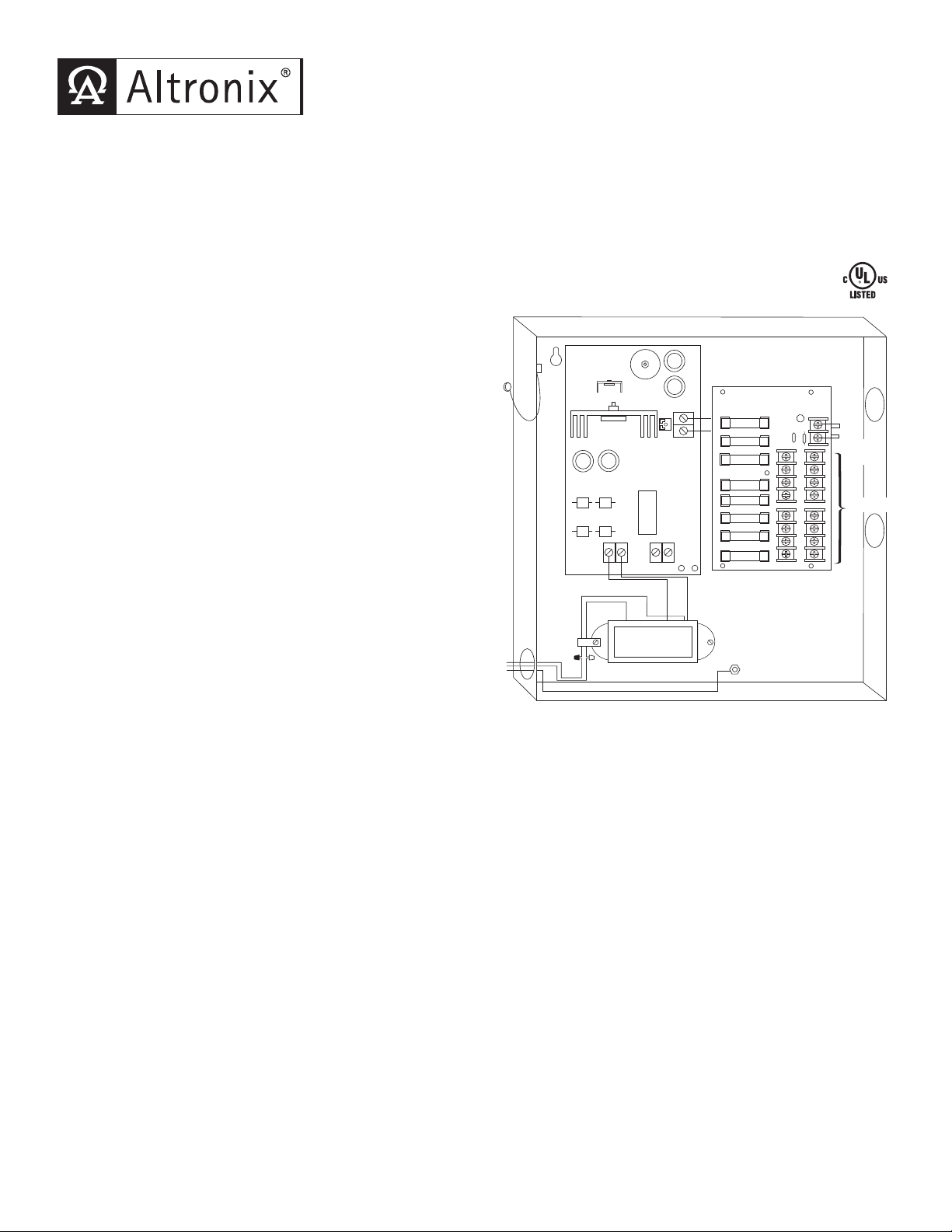
ALTV615DC8UL
Wire
Strap
(from
Enclosure
to Door)
+ DC OUTPUT ---
--- BAT +ACAC
DC
AC
N
COMMON POWER OUTPUTS
P
FUSED POWER OUTPUTS
1 2 3 4 5 6 7 8
D1
INPUT
R1
LED
XFMR
Black
Lead
White
L
ead
Green
Lead
1
15VAC input
50/60 Hz,
.
9 amp
n
on power-
limited
Voltage
Adjustment
U
se separate
knockouts for
power-limited
circuits.
Class 2 Not Wet/
C
lass 3 Wet
CCTV Camera & Accessory Power Supply
Rev. 042806
Overview:
The Altronix ALTV615DC8UL CCTV Power Supply is designed with eight (8) individually fused power limited, Class 2
Rated outputs for powering CCTV Cameras and other video accessories. It will provide 6VDC-15VDC distributed via
eight (8) fused outputs with a total of up to 4 amp continuous supply current.
Specifications:
Agency Listings:
• UL Listed for Commercial Closed-Circuit Television Equipment (UL 2044).
•
CUL Listed - CSA Standard C22.2 No.1-98, Audio, Video and Similar Equipment.
Input:
• Input 115VAC 50/60 Hz, .9 amp.
Output:
• 6VDC-15VDC adjustable output.
•
Eight (8) individually fuse protected power limited,
Class 2 Rated outputs.
• 4 amp total continuous supply current.
• Filtered and electronically regulated outputs.
Fuse Ratings:
• Output fuses are rated at 3.5 amp/250VAC (Fig. 1).
Visual Indicators:
• AC input and DC output LED indicators.
Additional Features:
• Spare fuses included.
• Unit maintains camera synchronization.
• Ease of installation saves time and eliminates costly labor.
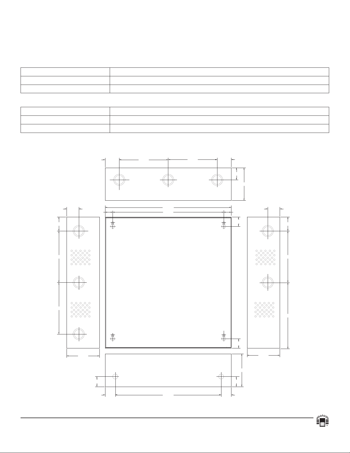
Enclosure Dimensions:
13.5"H x 13"W x 3.25"D
Note: Add suffix “3” for 3-wire line cord
(e.g. ALTV615DC8UL3) and disregard
installation instruction number two (2).
Installation Instructions:
1. Mount ALTV615DC8UL in desired location.
2. Connect green lead to earth ground. Connect AC (115VAC 50/60 Hz) to the black and white flying leads of the
transformer (Fig. 1). Use knockout adjacent to the transformer 1/4” spacing must be pro
wiring and all other circuits.
3. Adjust output voltage using trimpot on the board prior to connecting CCTV devices.
4. Measure output voltage before connecting devices. This helps avoid potential damage.
Terminals marked [1P-8P] are positive (+) and terminals marked [1N-8N] are negative.
CAUTION: Determine the maxim
output voltage.
5. Connect each DC CCTV cameras to terminal pairs marked [1P-1N thru 8P-8N] on PD8 board carefully
obser
ving correct polarity (Fig. 1).
6. Green LED will illuminate w
um operating voltage of the equipment being powered before adjusting the
hen when unit is powered.
7. Upon completion of wiring, secure enclosure door with screws (supplied).
Keep power limited circuits (outputs 1 through 8) away from non-power limited, 1/4” space must be provided.
Use separ
ate knockouts.
Caution: Equipment to be installed / serviced by authorized / trained personnel only.
Shut branch circuit power before installing / servicing equipment.
vided between AC input
Fig. 1
Page 2
WARNING: To reduce the risk of fire or electric shock, do not expose the unit to rain or moisture.
5.10"
6.5625"
3.25"3.25"
5.10"
5.10"
3.25"
1.00"10.50"1.00"
1.00"
1.00"
1
.40"
1
.20"
1.40"
1
.20"
0
.75
"
0.75" 11.00"
1
2.50"
3.25"
0.9375"
0.9375"
1
.40" 4.85" 4.85" 1.40"
1.20"
Bottom
Top
RightLeft
This installation should be made by qualified service personnel and should conform to NEC and all
local codes.
Terminal Identification:
AL400ULB - Power Supply Board
Terminal Legend Function/Description
AC/AC Low voltage AC input (24VAC 100VA) Altronix part #T24130.
+ DC --- 6VDC-15VDC @ 4 amp total continuous output.
PD8 - Distribution Module
Terminal Legend Function/Description
1P - 8P Positive DC output, Class 2, power limited.
1N - 8N Negative DC output, Class 2, power limited.
Enclosure Dimensions:
13.5”H x 13”W x 3.25”D
Altronix is not responsible for any typographical errors.
140 58th Street, Brooklyn, New York 11220 USA, 718-567-8181, fax: 718-567-9056
web site: www.altronix.com, e-mail: info@altronix.com, Lifetime Warranty, Made in U.S.A.
IIALTV615DC8UL D30J
MEMBER
 Loading...