

Altronix ALTV615DC416220, ALTV615DC616220, ALTV615DC44M220, ALTV615DC1016220, ALTV615DC44CBM220 Installation Manual
...Page 1

ALTV615DC220 Series
CCTV Power Supplies
Installation Guide
Models Include:
• ALTV615DC44M220 • ALTV615DC44CBM220
- 6-15VDC @ 4A - 6-15VDC @ 4A
- Four (4) Fuse Protected Outputs. - Four (4) PTC Protected Outputs.
• ALTV615DC48M220 • ALTV615DC48CBM220
- 6-15VDC @ 4A - 6-15VDC @ 4A
- Eight (8) Fuse Protected Outputs. - Eight (8) PTC Protected Outputs.
• ALTV615DC416220 • ALTV615DC416CB220
- 6-15VDC @ 4A - 6-15VDC @ 4A
- Sixteen (16) Fuse Protected Outputs. - Sixteen (16) PTC Protected Outputs.
• ALTV615DC616220 • ALTV615DC616CB220
- 6-15VDC @ 6A - 6-15VDC @ 6A
- Sixteen (16) Fuse Protected Outputs. - Sixteen (16) PTC Protected Outputs.
• ALTV615DC1016220 • ALTV615DC1016CB220
- 6-15VDC @ 10A - 6-15VDC @ 10A
- Sixteen (16) Fuse Protected Outputs. - Sixteen (16) PTC Protected Outputs.
Rev. 032306
Page 2

Overview:
3.5A 250V
For continuous protection against
risk of fire replace fuses with
same type and rating.
common
outputs
protected
outputs
P
N
NPS
XFMR Input
PD16W
12345678
9 10 11 12 13 14 15 16
NP
XFMR XFMR
Power Supply
Board
DC outputs
Power
Switch
ALTV615DC220 Series DC CCTV Power Supplies provide 6-15VDC distributed via fuse or PTC protected outputs for
powering CCTV cameras, heaters, and other video accessories.
ALTV615DC220 Reference Chart:
Total
Output
Altronix
Model Number
ALTV615DC44M220
ALTV615DC44CBM220
ALTV615DC48M220
ALTV615DC48CBM220
ALTV615DC416220
ALTV615DC416CB220
ALTV615DC616220
ALTV615DC616CB220
ALTV615DC1016220
ALTV615DC1016CB220
Output
Voltage
Current
(Power)
6-15VDC 4A 4 6-15VDC 4A 4
6-15VDC 4A 8 6-15VDC 4A 8
6-15VDC 4A 16 6-15VDC 4A 16
6-15VDC 6A 16 6-15VDC 6A 16
6-15VDC 10A 16 6-15VDC 10A 16
Specifications:
Agnecy Listing:
• CE European Conformity.
Input:
• 220VAC (working range 198VAC-256VAC), 50/60Hz.
Output:
• Four (4), eight (8), or sixteen (16) individual outputs.
• 6VDC to 15VDC field adjustable.
• Outputs are rated @ 3.5A (fused) or 2.5A (PTC).
• Filtered and electronically regulated outputs.
Features:
• AC input and DC output LED indicators.
Number
of
Outputs
PTC
Protected
Outputs
P
P
P
P
P
Output
Fuse
Protected
Outputs
P
Current
(max per
output)
3.5A 0.5A
- 2.5A 0.5A
P
3.5A 0.5A
- 2.5A 0.5A
P
3.5A 0.5A
- 2.5A 0.5A
P
3.5A 1A
- 2.5A 1A
P
3.5A 1A
- 2.5A 1A
220VAC
50/60Hz
Current
Features (cont’d):
• Power ON/OFF switch.
• Unit maintains camera synchronization.
• Ease of installation saves time and eliminates
costly labor.
Enclosure Dimensions (H x W x D approx.):
ALTV615DC44M220, ALTV615DC44CBM220,
ALTV615DC48M220, ALTV615DC48CBM220,
8.5” x 7.5” x 3.75” (215.9mm x 190.5mm x 95.25mm)
All other models:
13.5” x 13” x 3.25” (342.9mm x 330.2mm x 82.55mm)
Input
CAUTION: This installation should be made by qualified service personnel and should conform to the
National Electrical Code and all local codes.
Installation Instructions:
1. Mount unit in the desired location. Mark and predrill holes in the wall to line up with the top two keyholes in the
enclosure. Install two upper fasteners and screws in the wall with the screw heads protruding. Place the enclosure’s
upper keyholes over the two upper screws, level and secure. Mark the position of the lower two holes. Remove the
enclosure. Drill the lower holes and install the three fasteners. Place the enclosure’s upper keyholes over the two
upper screws. Install the two lower screws and make sure to tighten all screws (Enclosure Dimensions, pg. 7, 8).
2. Remove Power Distribution Module and isolation barrier (models with “M” suffix only).
3. Connect unswitched AC circuit (220VAC, 50/60Hz) as follows: Green branch wire (ground) connects to the terminal
marked , Line connects to the terminal marked [L], and Neutral connects to the terminal marked [N] of the Inlet
Appliance Connector. (Figs. 1-4, pgs. 4-6). Use 18 AWG or larger for all power connections.
Units with line cord installed skip Instruction #3.
Use 18 AWG or larger for all power connections. Connect green ground lead to earth ground (Fig. 1-4, pgs. 4-6).
Keep power-limited wiring separate from non power-limited wiring. Minimum 0.25” spacing must be provided.
Use separate knockouts.
4. Adjust output voltage (unit is factory set at 12VDC): use the trimpot on the power supply board
prior to connecting CCTV devices.
5. Measure output voltage before connecting devices. This helps avoiding potential damage.
CAUTION: Determine the maximum operating voltage of the equipment being powered before adjusting the
output voltage.
- 2 - ALTV615DC220 Series
Page 3
6. Reinstall isolation barrier and Power Distribution Module (models with “M” suffix only).
7. Connect devices to terminals marked [1P - 1N] through [4P - 4N] on PD4/PD4CB board,
[1P - 1N] through [8P - 8N] on PD8/PD8CB, [1P - 1N] through [16P - 16N] on PD16W/PD16WCB/PD16CB board,
carefully observing correct polarity (Figs. 1-4, pgs. 4-6).
Terminals marked [1P - 16P] are positive (+) and terminals marked [1N - 16N] are negative.
8. Green LED will illuminate when unit is powered.
9. Upon completion of the wiring, secure enclosure door with screws (supplied).
WARNING: To reduce the risk of fire or electric shock, do not expose the unit to rain or moisture.
Terminal Identification:
Power Supply Board
Terminal Legend Function/Description
AC/AC Low voltage AC input.
+ DC -- 6VDC-15VDC output.
PD4/PD4CB - Distribution Module
1P - 4P Positive DC outputs.
1N - 4N Negative DC outputs.
PD8/PD8CB - Distribution Module
1P - 8P Positive DC outputs.
1N - 8N Negative DC outputs.
PD16W/PD16WCB/PD16CB - Distribution Module
1P - 16P Positive DC outputs.
1N - 16N Negative DC outputs.
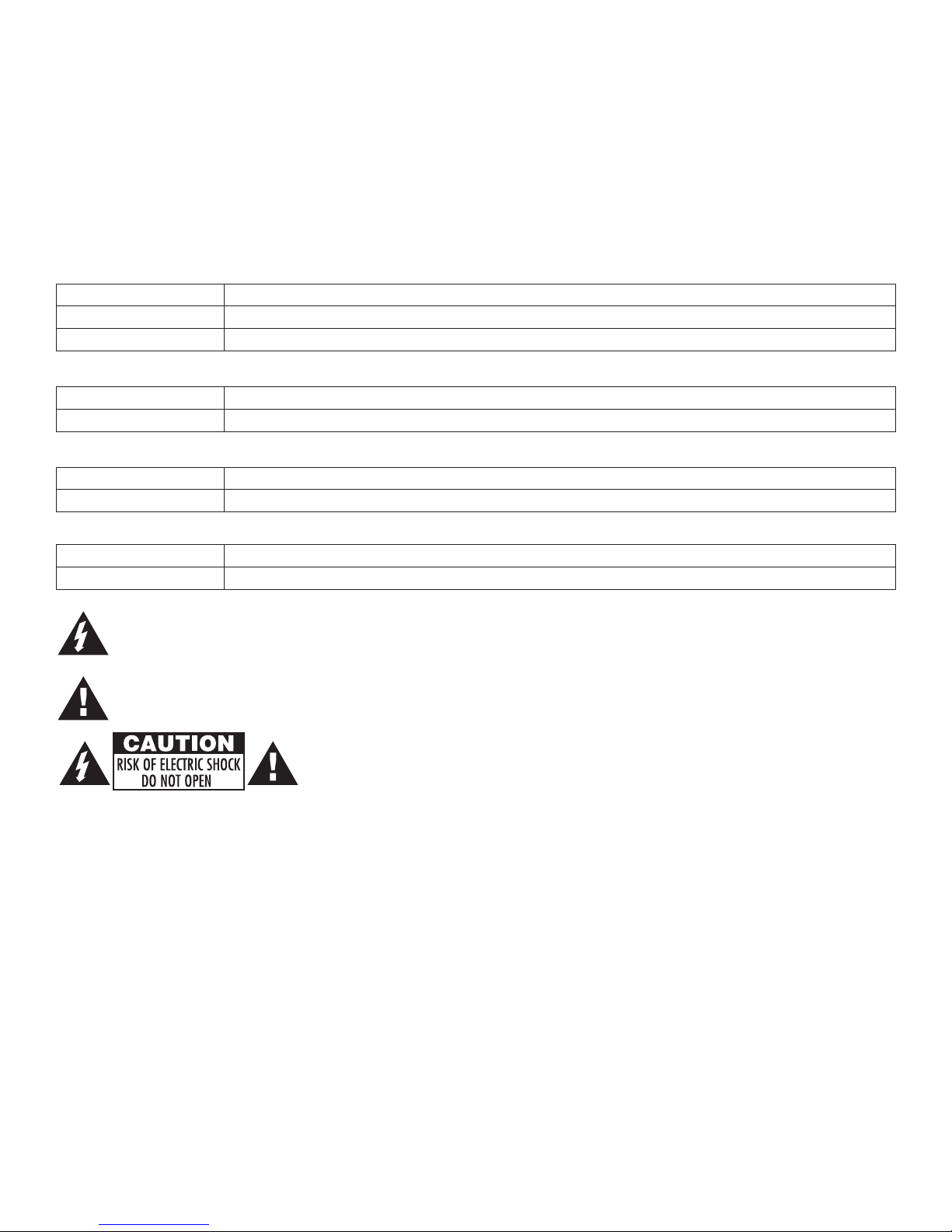
The lightning flash with arrow head symbol within an equilateral triangle is intended to alert the user to the
presence of an insulated DANGEROUS VOLTAGE within the product’s enclosure that may be of sufficient
magnitude to constitute an electric shock.
The exclamation point within an equilateral triangle is intended to alert the user to the presence of important
operating and maintenance (servicing) instructions in the literature accompanying the appliance.
CAUTION: To reduce the risk of electric shock do not open enclosure. There are
no user serviceable parts inside. Refer servicing to qualified service personnel.
ALTV615DC220 Series - 3 -
Page 4

Y
A
A
Fig. 1
BK
A
AC
ALTV615DC44M220 • ALTV615DC44CBM220
CAUTION: De-energize unit prior to servicing. For continued protection against fire hazard
replace fuse with the same type and rating. Do not expose unit to rain or moisture.
Used on PTC Models
(example: ALTV615DC44CBM220)
1P, 2P, 3P, 4P = FUSED OUTPUTS
1P 1N 2P 2N 3P 3N 4P 4N
INPUT
1N, 2N, 3N, 4N = COMMON OUTPUTS
LED
ON OFF
F1 F2 F3 F4
MAIN FUSE
Fig. 2
ALTV615DC48M220 • ALTV615DC48CBM220
Power
Supply
Board
Trimpot
Output Wiring
1P 1N 2P 2N 3P 3N 4P 4N
ALTRONIX CORP.
BKLYN., NY 11220
LED
INPUT
ON OFF
220VAC Input
50/60 Hz
1P, 2P, 3P, 4P = FUSED OUTPUTS
1N, 2N, 3N, 4N = COMMON OUTPUTS
3.5A 250V
3.5A 250V
AC AC
3.5A 250V
XFMR
MAIN FUSE
Barrier
CAUTION: De-energize unit prior to servicing. For continued protection against fire hazard
replace fuse with the same type and rating. Do not expose unit to rain or moisture.
Output Wiring
220VAC Input
50/60 Hz
Used on PTC Models
(example: ALTV615DC48CBM220)
Barrier
ALTRONIX CORP.
BKLYN., NY 11220
AC AC
Power
Supply
Board
Trimpot
SW1
ON OFF
+ DC --
SW1
ON OFF
- 4 - ALTV615DC220 Series
XFMR
Page 5

Fig. 3
ALTV615DC416220 • ALTV615DC416CB220 • ALTV615DC616220 • ALTV615DC61CB220
ALTV615DC1016220 • ALTV615DC1016CB220
CAUTION: De-energize unit prior to servicing. For continued protection against fire hazard
replace fuse with the same type and rating. Do not expose unit to rain or moisture.
DC outputs
Door
Wire Strap
Enclosure
(from
to Door)
12345678
common
outputs
protected
outputs
9 10 11 12 13 14 15 16
N
P
Power Supply
Board
For continuous protection against
PD16W
3.5A 250V
risk of fire replace fuses with
same type and rating.
NP
NPS
XFMR Input
Power
Switch
220VAC Input
50/60Hz
XFMR XFMR
DC outputs
outputs
9 10 11 12 13 14 15 16
N
P
N
NPS
P
XFMR Input
12345678
common
outputs
protected
Used on PTC Models
(example: ALTV615DC416CB220)
ALTV615DC220 Series - 5 -
PTCs
PD16W
Page 6

Notes:
- 6 - ALTV615DC220 Series
Page 7

Enclosure Dimensions for:
(
)
• ALTV615DC44M220 • ALTV615DC44CBM220 • ALTV615DC48M220 • ALTV615DC48CBM220
• ALTV615DC416CBM220
8.5” x 7.5” x 3.75” (215.9mm x 190.5mm x 95.25mm)
3.63”
(92.2mm)
1.25”
(31.75mm)
3.85”
(97.79mm)
7.25”
(184.15mm)
0.6”
(15.24mm)
0.9”
(22.86mm)
1”
(25.4mm)
1.25”
(31.75mm)
0.6”
(15.24mm)
0.9”
(22.86mm)
1.25”
(31.75mm)
1”
(25.4mm)
8.13”
(206.5mm)
(25.4mm)
1”
1.25”
(31.75mm)
3.85”
(97.79mm)
0.6”
(15.24mm)
1”
(25.4mm)
7.25”
184.15mm
0.6”
(15.24mm)
(206.5mm)
1”
(25.4mm)
1”
(25.4mm)
8.13”
3.85”
(97.79mm)
1.75”
(44.45mm)
1”
(25.4mm)
ALTV615DC220 Series - 7 -
Page 8

Enclosure Dimensions for:
(
)
(
)
(
)
• ALTV615DC416220 • ALTV615DC416CB220 • ALTV615DC616220 • ALTV615DC616CB220
• ALTV615DC1016220 • ALTV615DC1016CB220
13.5” x 13” x 3.25” (342.9mm x 330.2mm x 82.55mm)
1.40”
(36mm)
5.10”
(130mm)
1.20”
(31mm)
13.0”
(330mm)
(36mm)
0.75”
(19mm)
1.40”
4.85”
(123mm)
12.5”
(318mm)
11.0”
(279mm)
4.85”
(123mm)
1.40”
(36mm)
0.75”
(19mm)
1.20”
(31mm)
0.9375”
(24mm)
3.25”
(83mm)
1.20”
(31mm)
1.40”
(36mm)
5.10”
(130mm)
5.10”
(130mm)
3.25”
(83mm)
1.0”
(25mm)
1.0”
25mm
10.5”
267mm
1.0”
25mm
0.9375”
(24mm)
1.0”
(25mm)
3.25”
(83mm)
3.25”
(83mm)
6.5625”
(167mm)
Altronix is not responsible for any typographical errors.
140 58th Street, Brooklyn, New York 11220 USA, 718-567-8181, fax: 718-567-9056
web site: www.altronix.com, e-mail: info@altronix.com. Lifetime Warranty, Made in U.S.A.
II1ALTV615DC220 Series B23Q
- 8 - ALTV615DC220 Series
MEMBER
 Loading...