

Page 1

Isolated Series
CCTV Power Supplies
Installation Guide
Models Include:
• ALTV248HI • ALTV248CBHI
- 24VAC @ 14 amp total output. - 24VAC @ 14 amp total output.
- Eight (8) 1.75 amp Fuse Protected - Eight (8) 1.75 amp PTC Protected
Isolated Outputs. Isolated Outputs.
• ALTV248MI • ALTV248CBMI
- 24VAC @ 12.5 amp total output. - 24VAC @ 12.5 amp total output.
- Eight (8) 1.6 amp Fuse Protected - Eight (8) 1.6 amp PTC Protected
Isolated Outputs. Isolated Outputs.
• ALTV2416I • ALTV2416CBI
- 24VAC @ 28 amp total output. - 24VAC @ 28 amp total output.
- Sixteen (16) 1.75 amp Fuse Protected - Sixteen (16) 1.75 amp PTC Protected
Isolated Outputs. Isolated Outputs.
Rev. 081204
Page 2

Overview:
These Altronix Isolated CCTV Power Supplies provide 24VAC distributed via eight (8) or sixteen (16) fuse or
PTC protected isolated outputs for powering CCTV Cameras, heaters and other video accessories.
Isolated Power Supply Reference Chart:
rent
Altronix
Model Number
ALTV248HI 24VAC 14 amp 8 - x 1.75 amp 2.7 amp
ALTV248CBHI 24VAC 14 amp 8 x - 1.75 amp 2.7 amp
ALTV248MI 24VAC 12.5 amp 8 - x 1.6 amp 2.7 amp
ALTV248CBMI 24VAC 12.5 amp 8 x - 1.6 amp 2.7 amp
ALTV2416I 24VAC 28 amp 16 - x 1.75 amp 5.4 amp
ALTV2416CBI 24VAC 28 amp 16 x - 1.75 amp 5.4 amp
Output Voltage
(Power)
Total Output Cur
Outputs
Number of
PTC Protected
Outputs
Fuse Protected
Outputs
Output Current
(max per output)
50/60Hz Input
Current
115VAC
Specifications:
• Illuminated master Power ON/OFF switch
w/built in circuit breaker.
• Unit maintains camera synchronization.
• Ease of installation saves time & eliminates costly labor.
• Spare fuses included (on fuse protected models).
Enclosure Dimensions:
ALTV248MI, ALTV248CBMI: 8.5"H x 7.5"W x 3.5"D
ALTV248HI and ALTV248CBHI: 12.25"H x 7.75"W x
4.5"D
ALTV2416I and ALTV2416CBI:
13"H x 13.5"W x 3.25"D
Installation Instructions:
1. Mount unit in desired location.
wer switch to OFF positon on all models
Set po
2.
3. All units are factory set for 24VAC operation.
C power to the black and white flying leads of the transformer(s)
Connect
4.
Use 18 AWG or larger for all power connections.
Measure output v
5.
Terminals marked [1A - 8A] and [1B - 8B] are of the same polarity (phase).
6. Connect CCTV cameras to output terminals using the following procedure:
7. Set power switch on all models to the “RESET” (ON) position
Upon completion of wiring, secure enclosure door with scre
8.
Caution:
Shut branch circuit power before installing / servicing equipment.
A
oltage before connecting de
Camera 1 to output 1A & 1B
Camera 2 to output 2A & 2B. Camera 6 to output 6A & 6B.
Camera 3 to output 3A & 3B. Camera 7 to output 7A & 7B.
Camera 4 to output 4A & 4B. Camera 8 to output 8A & 8B.
Equipment to be installed / ser
. Camera 5 to output 5A & 5B.
viced b
igs. 1-3, pgs. 3-5)
(F
This helps a
vices.
y authorized / tr
.
oid potential damage.
v
(Figs. 1-3, pgs. 3-5).
ws (supplied).
ained per
igs. 1-3, pgs. 3-5)
(F
sonnel only.
.
WARNING: To reduce the risk of fire or electric shock, do not expose the unit to rain or moisture.
This installation should be made by qualified service personnel and should conform to all local codes
and in accordance with the National Electrical Code.
- 2 -
Page 3
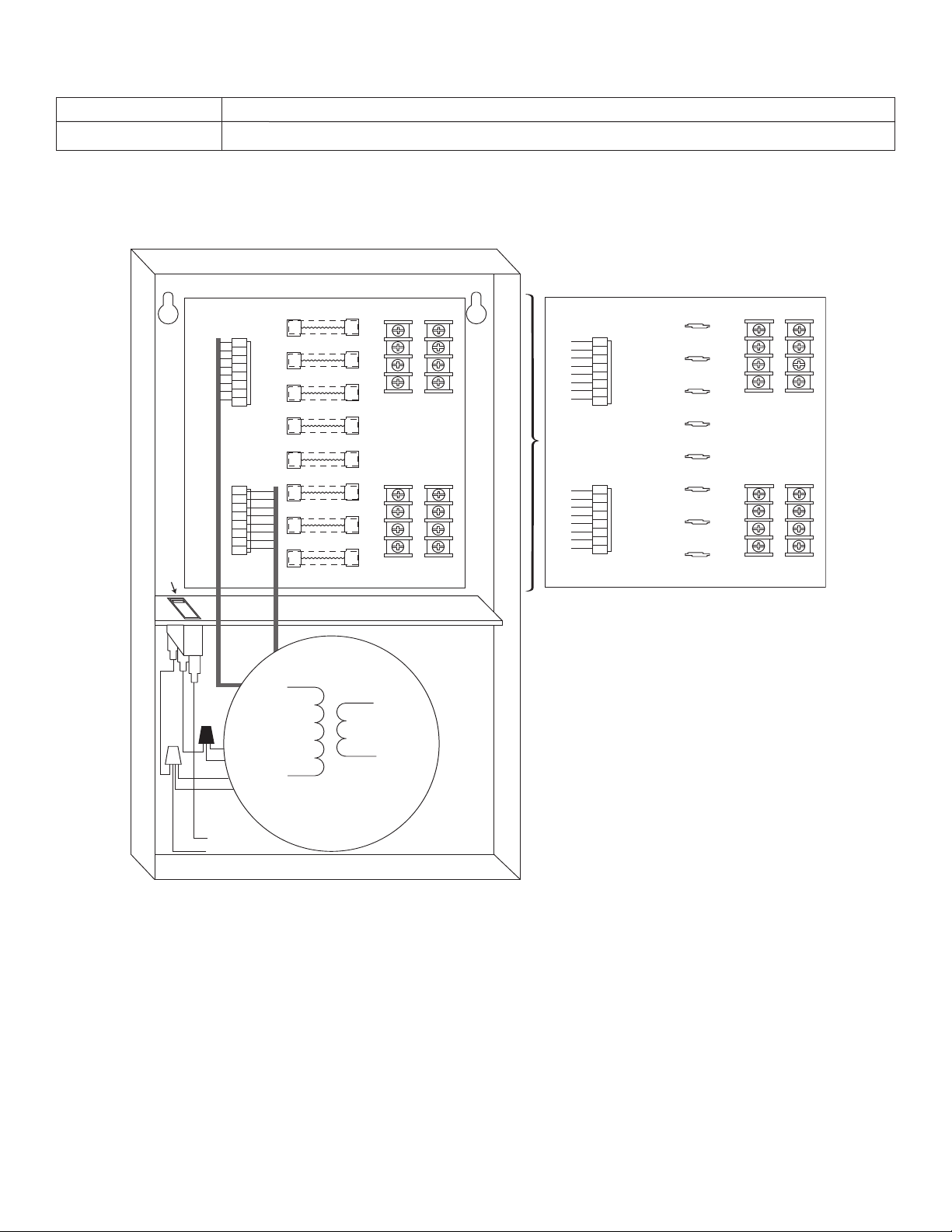
PD8I - Power Distribution Module
1A
F1 F2 F3 F4 F5 F6 F7 F8
2A 3A 4A 5A 6A 7A 8A
1B 2B 3B 4B 5B 6B 7B 8B
115VAC input
50/60 Hz
Power
Swit
ch
115VAC input
50/60 Hz
XFMR*
1A
F1 F2 F3 F4 F5 F6 F7 F8
2A 3A 4A 5A 6A 7A 8A
1B 2B 3B 4B 5B 6B 7B 8B
Used on PTC Models
(example: ALTV248CBI)
1A - 8A Phase 1.
1B - 8B Phase 2.
Fig. 1 - ALTV248HI • ALTV248CBHI
Terminal Identification:
- 3 -- 3 -
Page 4

Fig. 2 - ALTV248MI • ALTV248CBMI
Transformer
underneath
power supply
board
Power
Switch
1A
F1 F2 F3 F4 F5 F6 F7 F8
2A 3A 4A 5A 6A 7A 8A
1B 2B 3B 4B 5B 6B 7B 8B
1A
F1 F2 F3 F4 F5 F6 F7 F8
2A 3A 4A 5A 6A 7A 8A
1B 2B 3B 4B 5B 6B 7B 8B
Used on PTC Models
(example: ALTV248CBMI)
- 4 -
Page 5

Fig. 3 - ALTV2416I • ALTV2416CBI
115VAC input
50/60 Hz.
Power
Switch
1A
F1 F2 F3 F4 F5 F6 F7 F8
2A 3A 4A 5A 6A 7A 8A
1B 2B 3B 4B 5B 6B 7B 8B
1A
F1 F2 F3 F4 F5 F6 F7 F8
2A 3A 4A 5A 6A 7A 8A
1B 2B 3B 4B 5B 6B 7B 8B
XFMR* XFMR*
1A
F1 F2 F3 F4 F5 F6 F7 F8
2A 3A 4A 5A 6A 7A 8A
1B 2B 3B 4B 5B 6B 7B 8B
Use
d on PTC Models
(example: ALT V2416CBI)
- 5 -
Page 6

TOP ONLY
Enclosure Dimensions for:
• ALTV248MI
• ALTV248CBMI
8.5"H x 7.5"W x 3.5"D
- 6 -
Page 7

Enclosure Dimensions for:
• ALTV248HI
• ALTV248CBHI
12.25"H x 7.75"W x 4.5"D
- 7 -
Page 8

0
0
0
.81"
0
1
.1875"
1.1875"
3
.25"
3.25"
0
1.1875" 3.25".75" 1.5"
6
.25"
1
1"
1.4"
6.5"
5.5"
1.4"
11.66"
12.1"
13"
12.5"
1
1.75"
TOP ONLY
Enclosure Dimensions for:
• ALTV2416I
• ALTV2416CBI
13"H x 13.5"W x 3.5"D
Altronix is not responsible for any typographical errors.
Altronix Cor
140 58th Street, Brookl
eb site: www
w
IIisolatedSeries A07E
p.
.altronix.com, e-mail: info@altronix.com, Lifetime
York 11220 USA, 718-567-8181, fax: 718-567-9056
w
yn, Ne
ranty
ar
W
, Made in U.S.A.
MEMBER
- 8 -
 Loading...