

Page 1

ALTV248 Series
CCTV Power Supplies
Installation Guide
Models Include:
• ALTV248 • ALTV248CB
- 24VAC @ 4 amp (100VA). - 24VAC @ 4 amp (100VA).
or 28VAC @ 3.5 amp. or 28VAC @ 3.5 amp.
- Eight (8) Fuse Protected Outputs. - Eight (8) PTC Protected Outputs.
• ALTV248175 • ALTV248175CB
- 24VAC @ 7.25 amp (175VA). - 24VAC @ 7.25 amp (175VA).
or 28VAC @ 6.25 amp (175VA). or 28VAC @ 6.25 amp (175VA).
- Eight (8) Fuse Protected Outputs. - Eight (8) PTC Protected Outputs.
• ALTV248300 • ALTV248300CB
- 24VAC @ 14 amp (350VA) - 24VAC @ 14 amp (350VA)
or 28VAC @ 12.5 amp (350VA). or 28VAC @ 12.5 amp (350VA).
- Eight (8) Fuse Protected Outputs. - Eight (8) PTC Protected Outputs.
• ALTV248300M • ALTV248300CBM
- 24VAC @ 12.5 amp (300VA) - 24VAC @ 12.5 amp (300VA)
or 28VAC @ 10 amp (300VA). or 28VAC @ 10 amp (300VA).
- Eight (8) Fuse Protected Outputs. - Eight (8) PTC Protected Outputs.
• ALTV248600 • ALTV248600CB
- 24VAC @ 28 amp (700VA) - 24VAC @ 28 amp (700VA)
or 28VAC @ 25 amp (700VA). or 28VAC @ 25 amp (700VA).
- Eight (8) Fuse Protected Outputs. - Eight (8) PTC Protected Outputs.
Rev. 040904
Page 2

Overview:
These Altronix CCTV Power Supplies provide provide 24VAC/28VAC (ALTV248 and ALTV248CB provides24VAC
only) distributed via eight (8) fuse or PTC protected outputs for powering CCTV Cameras, heaters and other video
accessories.
Eight (8) Output ALTV248 Reference Chart:
Altronix
Model Number
ALTV248
ALTV248CB
ALTV248175
ALTV248175CB
ALTV248300
ALTV248300CB
Output Voltage
24VAC 4 amp
28VAC 3.5 amp
24VAC 4 amp
28VAC 3.5 amp
24VAC 7.25 amp
28VAC 6.25 amp
24VAC 7.25 amp
28VAC 6.25 amp
24VAC 14 amp
28VAC 12.5 amp
24VAC 14 amp
28VAC 12.5 amp
(Power)
Total Output Current
AC
Outputs
Number of
8 - x 3.5 amp 5 amp/250V .9 amp
8 x - 2.5 amp 5 amp/250V .9 amp
8 - x 3.5 amp 10 amp/250V 1.45 amp
8 x - 2.5 amp 10 amp/250V 1.45 amp
8 - x 3.5 amp
8 x - 2.5 amp
Outputs
PTC Protected
Outputs
Fuse Protected
(max per output)
Output Current
Main Fuse Ratings
on Board
15 amp/32V
15 amp/32V
50/60Hz Input
115V
2.7 amp
2.7 amp
Current
24VAC 12.5 amp
ALTV248300M
ALTV248300CBM
ALTV248600
ALTV248600CB
28VAC 10 amp
24VAC 12.5 amp
C 10 amp
A
28V
24VAC 28 amp
28VAC 25 amp
28 amp
C
A
24V
28VAC 25 amp
8 - x 3.5 amp
8 x - 2.5 amp
8 - x 3.5 amp (2) 15 amp/32V 5.4 amp
8 x - 2.5 amp (2) 15 amp/32V 5.4 amp
Specifications:
• Surge suppression.
• AC power LED indicator.
• Power ON/OFF switch.
• Unit maintains camera synchronization.
• Ease of installation saves time & eliminates costly labor.
• Spare fuses included (on fuse protected models).
Enclosure Dimensions:
ALTV248, ALTV248CB, ALTV248175 and
15 amp/32V
15 amp/32V
ALTV248175CB: 8.5"H x 7.5"W x 3.5"D
ALTV248300M and ALTV248300CBM:
8.5"H x 7.5"W x 3.75"D
TV248300CB:
TV248300 and
AL
12.5"H x 7.75"W x 4.5"D
ALTV248600 and ALTV248600CB:
13"H x 13.5"W x 3.25"D
- 2 -
AL
2.7 amp
2.7 amp
Page 3
Installation Instructions:
1.
Mount unit in desired location.
2.
Slide switch on PD board to OFF position for models ALTV248 and ALTV248CB
T
urn OFF main switch on all other models,
(F
igs. 3-5, pgs. 5-6).
(F
igs. 1 & 2, pg. 4)
3. All units are factory set for 24VAC operation.
For 28VAC operation, adjust unit prior to mounting and applying power as follows: Change the wire position so that
the black wire [28V] is connected to the terminal marked [P] and the yellow wire [24V] is connected to the terminal
marked [S]
.
4. Connect AC power to the black and white flying lead of the transformer(s) (Figs. 1-5, pgs. 4-6).
Use 18 AWG or larger for all power connections.
5. Measure output voltage before connecting devices. This helps avoid potential damage.
Terminals marked [1P - 8P] are positive of the same polarity.
CAUTION: Determine the maximum operating voltage of the equipment being powered before adjusting
the output voltage.
6. Connect devices to terminals marked [1P - 1N through 4P - 4N] on PD4/PD4CB board (Figs. 2 & 5, pgs. 4 & 6)
or terminals marked [1P - 1N through 8P - 8N] on PD8/PD8CB board (Figs. 1 & 3, pgs. 4-5), carefully
observing polarity.
7. Slide switch on PD board to ON position for models ALTV248 and ALTV248CB
Turn main switch on all other models to the “RESET” (ON) position
(Figs. 3-5, pgs. 5-6).
(Figs. 1 & 2, pg. 4).
8. Green LED will illuminate when unit is powered.
9. Upon completion of wiring, secure enclosure door with screws (supplied).
Caution: Equipment to be installed / serviced by authorized / trained personnel only.
Shut branch circuit power before installing / servicing equipment.
.
WARNING: To reduce the risk of fire or electric shock, do not expose the unit to rain or moisture.
This installation should be made by qualified service personnel and should conform to all local codes
and in accordance with the National Electrical Code.
Terminal Identification:
PD4/PD4CB - Power Distribution Module
1P - 4P AC output.
1N - 4N AC output.
PD8/PD8CB - Power Distribution Module
C output.
1P - 8P
1N - 8N AC output.
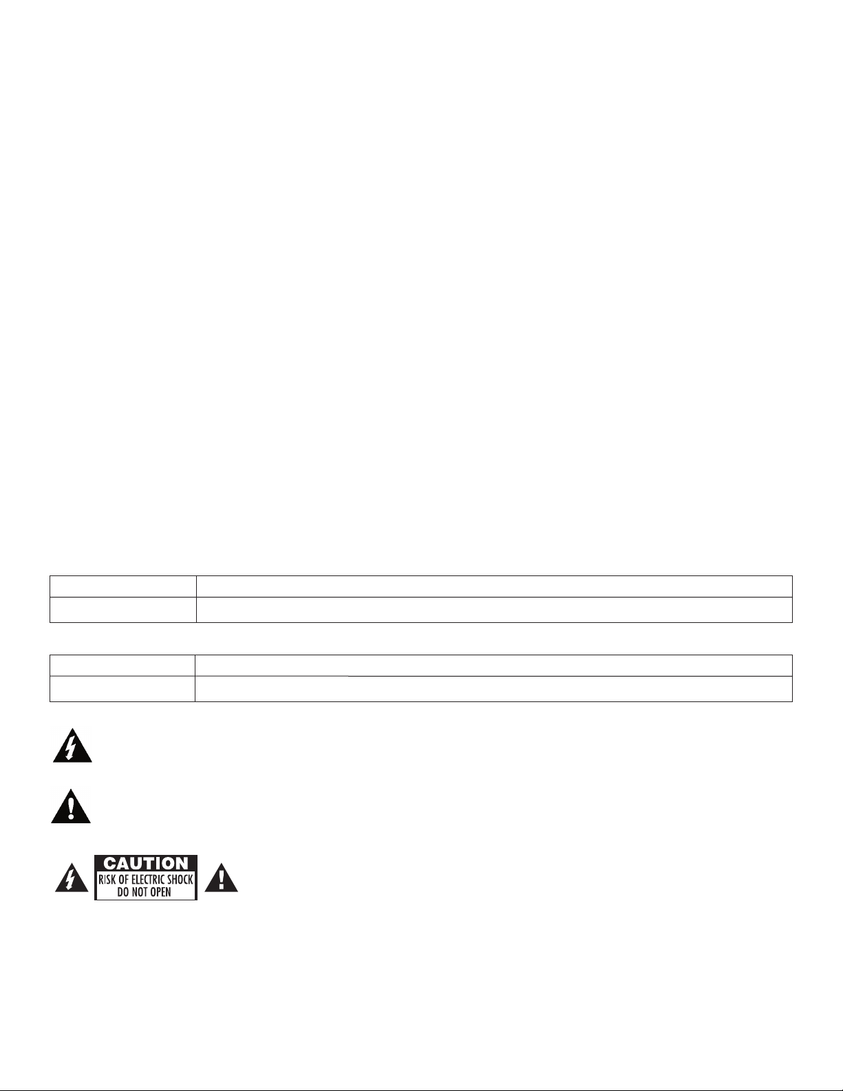
The lightning flash with arrow head symbol within an equilateral triangle is intended to alert the user to the
presence of an insulated “D
magnitude to constitute an electric shock.
The exclamation point within an equilateral triangle is intended to alert the user to the presence of important
operating and maintenance (servicing) instructions in the literature accompanying the appliance.
A
ANGER
OUS VOLTAGE” within the products enclosure that may be of sufficient
CAUTION: To reduce the risk of electric shock do not open enclosure. There are
no user serviceable parts inside. Refer servicing to qualified service personnel.
- 3 -
- 3 -
Page 4

Fig. 1 - ALTV248 • ALTV248CB
XFMR
11
5VAC input
50/60 Hz,
White Lead
Black
Lead
MAIN FUSE
ON OFF
N
COMMON POWER OUTPUTS
P
FUSED POWER
OUTPUTS
1 2
3 4 5 6 7 8
D1
INPUT
R1
LED
Used on PTC Models
(example: ALTV248CB)
NPS
NPS
24VAC or 28VAC circuit
breakered output 1
(Follow same procedure using
terminals 2P & N thru 8P & N
circuit breakered outputs 2 thru 8)
XFMR
White Lead
Power
Switch
Black
Lead
115VAC input
50/60 Hz,
1.5 amps
24 VAC or 28VAC fused output 1
(Follow same procedure
using terminals 2P & N
thru 8P & N fused
outputs 2 thru 8)
Used on PTC Models
(example: ALTV248175CB)
N
COMMON POWER OUTPUTS
P
FUSED POWER OUTPUTS
D1
INPUT
NPS
R1
LED
MAIN
FUSE
MAIN
FUSE
F1 F2 F3 F4 F5 F6 F7 F8
24VAC or 28VAC fused or PTC
protected outputs 1 through 8.
24VAC or 28VAC
fused or PTC protected outputs
1 through 8.
NP S
NP S
24VAC
Output
(Yellow) (Black)
(Black) (Yellow)
28VAC
Output
Voltage Selection
Configuration
Back Panel of Enclosure
Fig. 2 - ALTV248175 • ALTV248175CB
Terminal Blocks for Fig. 1
Terminal Blocks for Fig. 2
- 4 -
Page 5

Transformer
underneath
power supply
board
Power
Switch
White Lead
Black Lead
Used on PTC Models
(example: ALTV248300CBM)
N
COMMON POWER OUTPUTS
P
FUSED POWER OUTPUTS
D1
INPUT
N P S
R1
LED
MAIN
FUSE
MAIN
FUSE
F1 F2 F3 F4 F5 F6 F7 F8
Used on PTC Models
(example: ALTV248300CB)
N
COM
MON POWER OUTPUTS
P
FUSED POWER OUTPUTS
D1
INPUT
NPS
R1
LED
MAIN
FUSE
MAIN
FUSE
F1 F2 F3 F4 F5 F6 F7 F8
24VAC or 28VAC circuit
breakered output 1
(Follow same procedure using
terminals 2P & N thru 8P & N
cir
cuit breakered outputs 2 thru 8)
Fig. 3
24VAC or 28VAC
fused or PTC protected outputs
1 through 8.
24VAC or 28VAC
fused or PTC protected outputs
1 through 8.
NP S
NP S
24VAC
Output
(Yellow) (Black)
(Black) (Yellow)
28VAC
Output
ALTV248300 • ALTV248300CB
Voltage Selection
Configuration
Terminal Blocks for Fig. 3
Fig. 4 - ALTV248300M • ALTV248300CBM
Terminal Blocks for Fig. 4
- 5 -
Page 6

White
Lead
XFMR*
Black
Lead
115VAC input,
50/60 Hz.
XFMR*
INPUT
N P S
INPUT
N P S
Power
Swit
ch
Used on PTC Models
(example: ALTV248600CB)
INPUT
N P S
Fig. 5 - ALTV248600 • ALTV248600CB
24VAC or 28VAC
fused or PTC protected outputs
1 through 4.
NP S
NP S
24VAC
Output
(Yellow) (Black)
(Black) (Yellow)
28VAC
Output
Voltage Selection
Configuration
Terminal Blocks for Fig. 5
- 6 -
Page 7

TOP ONLY
Enclosure Dimensions for:
0.50”
6.05”
7.25”
3.85”
1.25”
3.625”
6.825” 8.125”
1.25”
1.00”
1.00”
1.00”
1.00”
1.00”
1.00”
5.25”
1.25”
7.25”
3.85”
3.85”
1.75”
Access for Linecord
• ALTV248
• ALTV248CB
• ALTV248175
• ALTV248175CB
8.5"H x 7.5"W x 3.5"D
Enclosure Dimensions for:
• ALTV248300M
• ALTV248300CBM
8.5"H x 7.5"W x 3.75"D
- 7 -
Page 8

00
0
.81"
0
1.1875"
1.1875"
3.25"
3.25"
0 1.1875" 3.25".75" 1.5" 6.25" 11"
1.4"
6.5"
5.5"
1.4"
11.66"
12.1"
13"
12.5"
11.75"
TOP ONLY
Enclosure Dimensions for:
• ALTV248300
• ALTV248300CB
12.25"H x 7.75"W x 4.5"D
Enclosure Dimensions for:
• ALTV248600
• ALTV248600CB
13"H x 13.5"W x 3.25"D
Altronix is not responsible for any typographical errors.
Altronix Corp.
140 58th Street, Brooklyn, Ne
web site: www.altronix.com, e-mail: info@altronix.com, Lifetime
II1ALTV248Series B08E
York 11220 USA, 718-567-8181, fax: 718-567-9056
w
ranty
ar
W
, Made in U.S.A.
MEMBER
- 8 -
 Loading...