

Page 1
BELLE
TDX 650A
870/10018/3
05/18
• Spare Parts Book
• Pièces Détachées
• Libro Despiece
• Lista de Peças
• Onderdelen Boekje
• Reservedele Skrift
• Ersatzteilhandbuch
• Manuale dei Ricambi
• Bruksanvisning
• Varaosaluettelo
• Lista Części Zamiennych
• Запасные Части Книга
• Част Списък
• Αντικατάσταση Κομμάτια Βιβλίο
• Část Barevný Pruh
• Részek Oldalra Dől
• Rezervni Djelovi Knjiga
240
GB
Operators Manual
US
Operators Manual
Manuel De L'Opérateur
F
Manual del Operador
E
Manual de Operação
P
NL
Handleiding
DK
Betjeningsvejledning
D
Bedienungshandbuch
I
Manuale Dell'Operatore
S
Bruksanvisning
SF
Käyttöohje
PL
Instrukcja Obsługi
RUS
Рyкoвoдcтвo для oпepaтopa
BG
Oпepaтop Pъчeн
GR
χειριστής χειροποίητοs
CZ
Na’vod K Obzluze
HUN
Kezelõk Kézi
HR
Uputstvo za rukovatelja
6
19
32
45
58
71
84
97
110
123
136
149
162
175
188
201
214
227
1
Page 2
EC DECLARATION OF CONFORMITY / DECLARATION CE DE CONFORMITE / DECLARACIÓN
DE CONFORMIDAD CE / DECLARAÇÃO CE DE CONFORMIDADE / EG-VERKLARING
VAN OVEREENSTEMMING / EF OVERENSSTEMMELSESERKLÆRING
We, Belle Group Sheen UK, Sheen, Nr. Buxton, Derbyshire, SK17 0EU, GB, hereby certify that if the product described within this certificate is bought from an
authorised Belle Group dealer within the EEC, it conforms to the following EEC directives: 2006/42/CE (This directive replaces directive 98/37/EC), Electromagnetic
GB
Compatibility Directive 2004/108/CE (as amended by 89/336/EEC, 92/31/EEC & 93/68 EEC). The Waste Electrical and Electronic Equipment (WEEE) 2002/96/CE, the
low voltage directive 2006/95/CE, BS EN ISO 12100-1:2003 Safety of machinery and associated harmonised standards, where applicable. Noise emissions conform to
directives 2000/14/EC Annex VI & 2005/88/EC, for machines under article 12 the notified body is AVT Reliability, Unit 2 Easter Court, Europa Boulevard, Warrington,
Cheshire, WA5 7ZB, GB.
Noise Technical Files are held at the Belle Group Head Office address which is stated above.
Nous soussignés, Belle Group Sheen UK, Sheen, Nr Buxton, Derbyshire, SK17 0EU, GB, certifions que si le produit décrit dans ce certificat est acheté chez un
distributeur autorisé Belle Group au sein de la CEE, il est conforme aux directives CEE ci-après: 2006/42/CE (Cette directive remplace la directive 98/37/CE), Directive
F
compatible pour l'électromagnisme 2004/108/CE (modifié par 89/336/EEC, 92/31/EEC & 93/68 EEC). Les déchets électriques, et d’équipement électronique 2002/96/CE,
caractéristiques basse tension 2006/95/CE, BS EN ISO 12100-1:2003 Directive de sécurité des machines et des critères associés et configurés, si applicable. Les
émissions de bruit sont conformes à la directive 2000/14/EC Annexe VI et 2005/88/EC pour machines , article 12, l’objet mentionné est AVT Reliability, Unit 2 Easter
Court, Europa Boulevard, Warrington, Cheshire, WA5 7ZB, GB.
Les fichiers techniques des émissions sonores sont détenus par Ray Neilson à l’adresse du Siège du Groupe Belle qui est indiqué ci-dessus.
La Sociedad, Belle Group Sheen UK, Sheen, Nr. Buxton, Derbyshire, SK 17 OEU, GB, por el presente documento certifica que si el producto descrito en este
certificado es comprado a un distribuidor autorizado de Belle Group en la CEE, este es conforme a las siguientes directivas: 2006/42/CE de la CEE (Esta directiva
E
sustituye a la Directiva 98/37/CE), Directiva 2004/108/CE sobre Compatibilidad Electromagnética (según enmiendas 89/336/EEC, 92/31/EEC & 93/68 EEC). Los
residuos eléctricos y electrónicos (RAEE) 2002/96/CE, Directiva sobre Bajo Voltaje 2006/95/CE, BS EN ISO 12100-1:2003 de Seguridad de Maquinaria y Niveles
armonizados estándares asociados donde sean aplicables. Emisión de Ruídos conforme a la Directiva 2000/14/CE Anexo VI y 2005/88/ECpara máquinas bajo artículo
12 la mencionada unidad está AVT Reliability, Unit 2 Easter Court, Europa Boulevard, Warrington, Cheshire, WA5 7ZB, GB.
En La Sede Central de Belle Group existen Archivos Técnicos con contenido referente a Niveles de Ruido.
O signatário, Belle Group Sheen UK, Sheen, Nr Buxton, Derbyshire, SK 0EU, GB, pelo presente, declara que se o produto descrito neste certificado foi adquirido a
um distribuidor autorizado do Belle Group em qualquer país da UE, está em conformidade com o estabelecido nas seguintes directivas comunitárias: 2006/42/CE (Esta
P
directiva substitui a Directiva 98/37/EC), Directiva de Compatibilidade Electromagnética 2004/108/CE (conforme corrigido pelas 89/336/EEC, 92/31/EEC & 93/68 EEC).
O Eléctrico de Desperdício e Equipamento Electrónico (DEEE) 2002/96/CE, a directiva de baixa voltagem 2006/95/CE, BS EN ISO 12100-1:2003 Segurança da
maquinaria e às normas harmonizadas afins se aplicáveis. As emissões de ruído respeitam e estão dentro das directivas para máquinas 2000/14/EC Anexo VI &
2005/88/EC, artigo 12, sendo o organismo notificado AVT Reliability, Unit 2 Easter Court, Europa Boulevard, Warrington, Cheshire, WA5 7ZB, GB.
A informação técnica sobre níveis sonoros está disponivel na Sede da Belle Group na morada acima mencionada.
Ondergetekende, Belle Group Sheen UK, Sheen, Nr. Buxton, Derbyshire, SK17 OEU, GB, verklaren hierbij dat als het product zoals beschreven in dit certificaat is
gekocht van een erkende Belle Group dealer binnen de EEG, het voldoet aan de volgende EEG richtlijnen: 2006/42/CE (Deze richtlijn vervangt Richtlijn 98/37/EC),
NL
Electromagnetische Compatability Richtlijn 2004/108/CE (geamendeerd door 89/336/EEC, 92/31/EEC & 93/68 EEC). De afgedankte elektrische en elektronische
apparatuur (AEEA) 2002/96/CE, de Laagspannings Richtlijn 2006/95/CE, BS EN ISO 12100-1:2003 Veiligheid van Machines en hieraan gekoppelde geharmoniseerde
Standaarden, waar deze van toepassing is. Geluidshinder te voldoen aan de richtlijnen 2000/14/EG en 2005/88/EG bijlage VI, voor toestel onder stuk 12 naar de notified
troep zit AVT Reliability, Unit 2 Easter Court, Europa Boulevard, Warrington, Cheshire, WA5 7ZB, GB.
Worden de Technische Dossiers van het lawaai gehouden op het adres van het Hoofdkantoor van de Groep Belle dat hierboven ' wordt verklaard.
Vi, Belle Group Sheen UK, Sheen, Nr. Buxton, Derbyshire, SK17 0EU, GB, erklærer hermed, at hvis det i dette certifikat beskrevne produkt er købt hos en autoriseret
Belle Group forhandler i EU, er det i overensstemmelse med følgende EØF-direktiver: 2006/42/CE (Dette direktiv erstatter direktiv 98/37/EF), 2004/108/EØF (som ændret
DK
ved 89/336/EEC, 92/31/EØF & 93/68 EØF), Affald af elektrisk og elektronisk udstyr (WEEE) 2002/96/CE, lavspændingsdirektivet 2006/95/CE, BS EN ISO 12100-1:2003
Maskinsikkerhed og tilhørende harmoniserede standarder, hvor det er relevant. Støjemission i overensstemmelse med direktiverne 2000/14/EF bilag VI og 2005/88/EF.
for maskiner under paragraf 12. Det bemyndigede organ er AVT Reliability, Unit 2 Easter Court, Europa Boulevard, Warrington, Cheshire, WA5 7ZB, Storbritanien.
De tekniske støjspecifikationer forefindes på Belle Group´s hovedkontor, adressen er skrevet ovenfor.
PRODUCT TYPE................. TYPE DE PRODUIT.............. TIPO DE PRODUCTO..........
MODEL................................. MODELE............................... MODELO..............................
SERIAL No........................... N° DE SERIE........................ N° DE SERIE........................
DATE OF MANUFACTURE. DATE DE FABRICATION..... FECHA DE FABRICACIÓN..
SOUND POWER LEVEL NIVEAU DE PUISSANCE NIVEL DE POTENCIA
MEASURED / SONORE MESUREE / ACÚSTICA MEDIDO /
....................(GUARANTEED) ............................(GARANTIE) ..................(GARANTIZADO)
WEIGHT............................... POIDS................................... PESO....................................
TIPO DE PRODUCTO.......... PRODUCTTYPE................... PRODUKTTYPE...................
MODELO.............................. MODEL................................. MODEL.................................
NO. DE SÉRIE..................... SERIENUMMER................... SERIENR..............................
DATA DE FABRIC................ FABRICAGEDATUM............ FREMSTILLINGSDATO.......
NIVEL DE POTÊNCIA GEMETEN LYDEFFEKTNIVEAU
DE SOM MEDIDO / GELUIDSSTERKTENIVEAU / MÅLT /
.......................(GARANTIDO) ...............(GEGARANDEERD) ...................(GARANTERET)
PESO.................................... GEWICHT............................. VÆGT...................................
Place of Declaration - Sheen, Nr. Buxton, Derbyshire, SK17 0EU, UK Date of Declaration - 2014...........................................................................
Lieu de déclaration - Sheen, Nr. Buxton, Derbyshire, SK17 0EU, UK Date de déclaration - 2014...........................................................................
Declaración hecha en - Sheen, Nr. Buxton, Derbyshire, SK17 0EU, UK Fecha de la declarachón - 2014..................................................................
Lugar de Declaração - Sheen, Nr. Buxton, Derbyshire, SK17 0EU, UK Data da Declaração - 2014...........................................................................
Plaats van de Verklaring - Sheen, Nr. Buxton, Derbyshire, SK17 0EU, UK Datum van de verklaring - 2014..................................................................
Sted i erklæring - Sheen, Nr. Buxton, Derbyshire, SK17 0EU, UK Dato for erklæringen - 2014.........................................................................
Signed by:
Signature:
Medido por:
Assinado por:
Getekend door:
Uunderskrevetaf:
Managing Director - On behalf of BELLE GROUP (SHEEN) UK.
Le Directeur Général - Pour le compte de la SOCIETE BELLE GROUP (SHEEN) UK.
Director Gerente - En nombre de BELLE GROUP (SHEEN) UK.
Director-Geral - Em nome de BELLE GROUP (SHEEN) UK.
Algemeen Directeur - Namens BELLE GROUP (SHEEN) UK.
Administrerende direktør – På vegne af BELLE GROUP (SHEEN) UK.
Ray Neilson
2
Page 3

EGKONFORMITÄTSERKLÄRUNG / DICHIARAZIONE CE DI CONFORMITÁ / EG-VERKLARING VAN
OVEREENSTEMMING / EC SAMSVARSERKLÆRING / EY-YHDENMUKAISUUSILMOITUS /
DEKLARACJA ZGODNOSCI Z PRZEPISAMI UE
Wir, Belle Group Sheen UK, Sheen, Nr. Buxton, Derbyshire, SK17 0EU, GB, bestätige hiermit, dass, wenn das Produkt innerhalb dieser Bescheinigung ist von einem
gekauft zugelassen Belle Group-Händler innerhalb der EWG, so entspricht sie den folgenden EG-Richtlinien: 2006/42/CE (Diese Richtlinie ersetzt die Richtlinie
D
98/37/EG), elektromagnetische Kompatibilität Richtlinie 2004/108/EG (geändert durch 89/336/EWG, 92/31/EWG und 93/68 EWG). Die Elektro-und Elektronik-Altgeräte
(WEEE) 2002/96/CE, der Niederspannungs-Richtlinie 2006/95/CE, BS EN ISO 12100-1:2003 Sicherheit von Maschinen und der damit verbundenen harmonisierten
Normen, sofern zutreffend. Geräuschemissionen entsprechen der Richtlinie 2000/14/EG Anhang VI und 2005/88/EG, für Maschinen gemäß Artikel 12 der benannten
Stelle ist AVT Reliability, Unit 2 Easter Court, Europa Boulevard, Warrington, Cheshire, WA5 7ZB, GB.
Geräuschtechnische Dokumente stehen in unserer Zentrale unter obig angegebener Adresse zur Verfügung.
Il Gruppo Belle Sheen UK, Sheen, Nr. Buxton, Derbyshire, SK17 0EU, GB, certifica che, se il prodotto descritto nel presente certificato viene acquistato da un
rivenditore autorizzato Belle gruppo all'interno della CEE, è conforme alle seguenti direttive CEE: 2006/42/CE (presente direttiva sostituisce la direttiva 98/37/CE),
I
elettromagnetica compatibilità con la direttiva 2004/108/CE (modificata dalla 89/336/CEE, 92/31/CEE e 93/68 CEE). L'Elettrico di Spreco e l'Apparecchiatura Elettronica
(WEEE) 2002/96/CE, la direttiva bassa tensione 2006/95/CE, BS EN ISO 12100-1:2003 Sicurezza del macchinario e le relative norme armonizzate, se del caso.
Emissioni sonore conformi alla direttiva 2000/14/CE, allegato VI e 2005/88/EG, per le macchine a norma dell'articolo 12, l'organismo notificato AVT Reliability, Unit 2
Easter Court, Europa Boulevard, Warrington, Cheshire, WA5 7ZB, GB.
Dati tecnici relativi ai livelli acustici sono disponibili su richiesta dalla sede madre Belle Group al sopra citato indirizzo.
Undertecknade, Belle Group Sheen UK, Sheen, Nr Buxton, Derbyshire, SK17 0EU, Storbritannien, intygar härmed att om den produkt som beskrivs i detta intyg är
köpt från en auktoriserad Belle-återförsäljare inom EEG, överensstämmer med följande EEG-direktiv: 2006/42/CE (Detta direktiv ersätter direktiv 98/37/EG),
S
Elektromagnetisk kompatibilitet 2004/108/CE (ändrat genom direktiv 89/336/EEG, 92/31/EEG och 93/68 EEG). Avfall från elektriska och elektroniska produkter (WEEE)
2002/96/CE, lågspänningsdirektivet 2006/95/CE, BS EN ISO 12100-1:2003 Maskinsäkerhet och tillhörande harmoniserade standarder, i förekommande fall. Buller följa
direktiv 2000/14/EG bilaga VI och 2005/88/EG till maskiner enligt artikel 12 anmälda organet är AVT Reliability, Unit 2 Easter Court, Europa Boulevard, Warrington,
Cheshire, WA5 7ZB, Storbritannien.
Teknisk dokumentation vad gäller test av maskiners ljud/bullernivå finns dokumenterad hos Belle-Groups huvudkontor i Sheen, England.
Vi, Belle Group Sheen UK, Sheen, Nr Buxton, Derbyshire, SK17 0EU, GB, herved bekrefte at hvis produktet er beskrevet i dette sertifikatet er kjøpt fra en autorisert
Belle Group forhandler innenfor EØS, følger det med til følgende EEC direktiver: 2006/42/CE (Dette direktivet erstatter direktiv 98/37/EF), Det elektromagnetisk
NO
kompatabiltets-direktivet 2004/108/CE (endret ved 89/336/EEC, 92/31/EEC og 93/68 EEC). Avfallet Elektrisk og Elektronisk Utstyr (WEEE) 2002/96/CE,
Lavspenningsdirektivet 2006/95/CE, BS EN ISO 12100-1:2003 Sikkerhet av maskiner og tilhørende harmoniserte standarder, der dette er aktuelt. Lydeffekt samsvar med
direktiv 2000/14/EC vedlegg VI og 2005/88/EG, for maskiner i henhold til artikkel 12 i meldte organ er AVT Reliability, Unit 2 Easter Court, Europa Boulevard,
Warrington, Cheshire, WA5 7ZB, GB.
Lydtekniske filer er arkivert hos Bell Group Hovedkontor med adresse som nevnt ovenfor.
Me, Belle Group Sheen UK, Sheen, Nr. Buxton, Derbyshire, SK17 0EU, GB, todistaa, että jos tuote on kuvattu tämän todistuksen ostetaan valtuutetun Belle
jälleenmyyjä ETY: n sisällä, se täyttää seuraavat EY-direktiiveihin: 2006/42/EY (tällä direktiivillä korvataan direktiivi 98/37/EY), sähkömagneettinen yhteensopivuutta
SF
direktiivin 2004/108/CE (muutettuna 89/336/ETY, 92/31/ETY ja 93/68 ETY). Tuhlaa Sähkö ja Sähköinen Varusteet (WEEE) 2002/96/CE, the matalajännitedirektiivistä
2006/95/CE, SFS-EN ISO 12100-1:2003 Koneturvallisuus ja niihin liittyvien yhdenmukaistettujen standardien tarvittaessa. Melupäästöjä täyttävät direktiivin 2000/14/EY
liitteessä VI ja 2005/88/EG, koneiden 12 artiklan mukaisesti ilmoitetun laitoksen on AVT Reliability, Unit 2 Easter Court, Europa Boulevard, Warrington, Cheshire,
WA5 7ZB, GB.
Melumittausten teknilliset arvot ovat saatavana Belle Group pääkonttorin ylläolevasta osoitteesta.
0\%HOOH*URXS6KHHQ8.6KHHQ1U%X[WRQ'HUE\VKLUH6.(8:LHOND%U\WDQLDQLQLHMV]\PSRÑZLDGF]DP\LÝSURGXNWRSLVDQ\ZW\PÑZLDGHFWZLH]RVWD¦
]DNXSLRQ\RGDXWRU\]RZDQHM%HOOH*URXSZ8(LMHVW]JRGQ\]QDVW¿SXMºF\PLG\UHNW\ZDPL(82006/42/EY1LQLHMV]DG\UHNW\ZD]DVWĊSXMHG\UHNW\ZĊ(&
PL
'\UHNW\Zº]JRGQRÑFLHOHNWURPDJQHW\F]QHM2004/108/CE]SRSUDZNDPLZQLHVLRQ\PLSU]H]89/336/EEC, 92/31/EEC & 93/68 EEC8W\OL]DFMDVSU]ĊWXHOHNWU\F]QHJRL
elektronicznego 2002/96/CE, G\UHNW\ZºZVSUDZLHQLVNLFKQDSL¿²2006/95/CE, BS EN ISO 12100-1:2003%H]SLHF]HÇVWZRPDV]\QL]ZLº]DQHQRUP\KDUPRQL]DF\MQH
WDPJG]LHWRPD]DVWRVRZDQLH3R]LRPKD¦DVXMHVW]JRGQ\]'\UHNW\Zº(&=DOºF]QLN9,L2005/88/EGRUJDQL]DFMD]DZLDGDPLDQDRGQRÑQLH]JRGQRÑFLWRAVT
Reliability, Unit 2 Easter Court, Europa Boulevard, Warrington, Cheshire, WA5 7ZB, :LHOND%U\WDQLD
,QIRUPDFMH7HFKQLF]QHGRW\F]ąFHSR]LRPXKDáDVXVąSU]HFKRZ\ZDQHZ%HOOH*URXS±DGUHVSRZ\ĪHM
PRODUKTTYP..................... TIPO PRODOTTO................ PRODUKTTYP.....................
MODELL .............................. MODELLO............................ MODELL...............................
SERIENNR........................... SERIE N° .............................. SERIE NR. ...........................
HERSTELLUNGSDATU...... DATA DI FABBRICAZIONE.. TILLVERKNINGSDATUM.....
SCHALLLEISTUNGSPEGEL LIVELLO POTENZA LJUDSTYRKA
GEMESSEN / SONORA MISURATA / UPPMÄTT /
......................(GARANTIERT) .........................(GARANTITA) .................(GARANTERAD)
GEWICHT............................. PESO.................................... VIKT......................................
PRODUKTTYP..................... TUOTETYYPPI ..................... TYP PRODUKTO..................
MODELL .............................. MALLI................................... MODEL .................................
SERIE NR. ........................... VALMISTUSNRO................. Nr SERII................................
PRODUKSJONSDATO........ VALMISTUSPÄIVÄ.............. DATAPRODUKCJI ...............
ÄLYDKRAFTNIVÅ ÄNENVOIMAKKUUDEN POZIOM MOCY
MÅLT / TASO MITATTU /
.......................(GARANTERT) .................................(TAATTU) ...........(GWARANTOWANY)
VEKT.................................... MASSA................................. WAGA...................................
'ÛWI¿
KU ZMIERZONY /
Unterzeichnet vo:
Firmato da:
Undertecknat:
Signatur:
Allekirjoitus:
3RGSLVD¦:
Generaldirektor – Im auftrag von BELLE GROUP (SHEEN) UK.
Amministratore Delegato – Per conto di BELLE GROUP (SHEEN) UK.
V.D. – På vägnar av BELLE GROUP (SHEEN) UK.
Managing Director - På vegne av SOCIETE BELLE GROUP (SHEEN) UK.
Toimitusjohtaja - BELLE GROUP (SHEEN) UK: n puolesta.
'\UHNWRU=DU]»G]DM»F\ – w imieniu BELLE GROUP (SHEEN) UK
Ray Neilson
Erklärungsort - Sheen, Nr. Buxton, Derbyshire, SK17 0EU, UK Erklärungsdatum - 2014...............................................................................
Luogo de dichiarazione - Sheen, Nr. Buxton, Derbyshire, SK17 0EU, UK Data de dichiarazione - 2014.......................................................................
Plats av Förklaring - Sheen, Nr. Buxton, Derbyshire, SK17 0EU, UK Datum av Förklaring - 2014.........................................................................
Sted av Erklæring - Sheen, Nr. Buxton, Derbyshire, SK17 0EU, UK Dato av Erklæring - 2014.............................................................................
Julistuksen paikka - Sheen, Nr. Buxton, Derbyshire, SK17 0EU, UK Julistuksen päivämäärä - 2014 ...................................................................
Miejsce deklaracji - Sheen, Nr. Buxton, Derbyshire, SK17 0EU, UK Data deklaracji - 2014...................................................................................
3
Page 4
ɋȿɊɌɂɎɂɄȺɌɋɈɈɌȼȿɌɋɌȼɂə / EÜ VASTAVUSDEKLARATSIOON / ATBILSTĪBAS
DEKLARĀCIJA / ES ATITIKTIES DEKLARACIJA / £©²¤¢
¤²ǻǻǺǽȀȌȇǽǿǸȈǸȀȀǽȀȄȈǽȈǸȇ
Ɇɵɧɢɠɟɩɨɞɩɢɫɚɜɲɢɟɫɹɨɬɢɦɟɧɢ%HOOH*URXS6KHHQȼɟɥɢɤɨɛɪɢɬɚɧɢɹ6KHHQ1U%X[WRQ'HUE\VKLUH6.(8ȼɟɥɢɤɨɛɪɢɬɚɧɢɹɡɚɹɜɥɹɟɦɱɬɨɜɫɥɭɱɚɟ
ɟɫɥɢɨɩɢɫɚɧɧɚɹɜɞɚɧɧɨɦɫɟɪɬɢɮɢɤɚɬɟɩɪɨɞɭɤɰɢɹɛɵɥɚɩɪɢɨɛɪɟɬɟɧɚɭɭɩɨɥɧɨɦɨɱɟɧɧɨɝɨɩɪɟɞɫɬɚɜɢɬɟɥɹȻɟɥɥɟȽɪɭɩɜȿɋɬɨɨɧɚɫɨɨɬɜɟɬɫɬɜɭɟɬɫɥɟɞɭɸɳɢɦ
RUS
ɞɢɪɟɤɬɢɜɚɦȿɋ&(ɗɬɚɞɢɪɟɤɬɢɜɚɡɚɦɟɧɹɟɬɞɢɪɟɤɬɢɜɭȿȿɋɞɢɪɟɤɬɢɜɟɷɥɟɤɬɪɨɦɚɝɧɢɬɧɨɣɫɨɜɦɟɫɬɢɦɨɫɬɢ&(ɞɨɩɨɥɧɟɧɧɨɣ
((&((&((&ɍɬɢɥɢɡɚɰɢɢɷɥɟɤɬɪɢɱɟɫɤɨɝɨɢɷɥɟɤɬɪɨɧɧɨɝɨɨɛɨɪɭɞɨɜɚɧɢɹ:(((&(&(Ⱦɢɪɟɤɬɢɜɚɧɢɡɤɨɝɨ
ɧɚɩɪɹɠɟɧɢɹ%6(1,62Ȼɟɡɨɩɚɫɧɨɫɬɶɦɚɲɢɧɢɫɜɹɡɚɧɧɵɟɫɧɢɦɢɝɚɪɦɨɧɢɡɢɪɨɜɚɧɧɵɯɫɬɚɧɞɚɪɬɨɜɝɞɟɷɬɨɩɪɢɦɟɧɢɦɨɍɪɨɜɟɧɶɲɭɦɚ
ɫɨɨɬɜɟɬɫɬɜɭɟɬɞɢɪɟɤɬɢɜɚɦ(&ɉɪɢɥɨɠɟɧɢɟ9,ɢ(&ɞɥɹɦɚɲɢɧɭɤɚɡɚɧɧɵɯɜɫɬɚɬɶɟɭɩɨɥɧɨɦɨɱɟɧɧɵɣɨɪɝɚɧAVT Reliability, Unit 2 Easter
Court, Europa Boulevard, Warrington, Cheshire, WA5 7ZB, GB.
ɒɭɦɬɟɯɧɢɱɟɫɤɨɝɨɮɚɣɥɵɯɪɚɧɹɬɫɹɊɷɣɇɟɥɶɫɨɧɧɚɪɭɤɨɜɨɞɢɬɟɥɹɝɪɭɩɩɵ%HOOHɍɩɪɚɜɥɟɧɢɹɚɞɪɟɫɤɨɬɨɪɵɣɭɤɚɡɚɧɜɵɲɟ
0HLHBelle Group Sheen UK, Sheen, Nr Buxton, Derbyshire, SK17 0EU, GBNLQQLWDQHWNXLNLUMHOGDWXGWRRWHMRRNVXONlHVROHYDVHUWLILNDDGLRQRVWHWXGOXEDWXG%HOOH
QLPHOYDKHQGDMDMRRNVXO(0hVHHYDVWDEMlUJPLVWHOH(0hGLUHNWLLYLGHOH&(NlHVROHYGLUHNWLLYDVHQGDEGLUHNWLLYL(hHOHNWURPDJQHWLOLVHKLOGXYXVH
EST
GLUHNWLLYL&(PXXGHWXG(0h(0hMD(0h-DHOHNWURRQLNDVHDGPHWHMllWPHWH:(((&(PDGDOSLQJHGLUHNWLLYL&(
%6(1,620DVLQDWHRKXWXVQLQJVHOOHJDVHRWXGKWOXVWDWXGVWDQGDUGLWHOHNXLVHHRQNRKDOGDWDY0UDRVDVYDVWDPDGLUHNWLLYL(h9,OLVDMD
(hPDVLQDWHDUWLNOLNRKDVHOWWHDYLWDWXGDVXWXVRQAVT Reliability, Unit 2 Easter Court, Europa Boulevard, Warrington, Cheshire, WA5 7ZB, GB.
Müra Tehniline faile hoitakse Ray Neilson kell Belle grupi peakontor aadress, mis on märgitud eespool.
0ƝV%HOOH*URXS6KHHQ8.1U%X[WRQ'HUE\UVKLUH6.(8DUãRDSOLHFLQƗPDUãRDSOLHFLQXNDJDGƯMXPƗMDSURGXNWVDSUDNVWƯWVãDMƗVHUWLILNƗWƗLULHJƗGƗMLHV
QRSLOQYDURWD%HOOHJUXSDVGƯOHUDWHULWRULMƗ((.WƗDWELOVWãƗGƗP(.GLUHNWƯYƗP&(âƯGLUHNWƯYDDL]YLHWR'LUHNWƯYX(.(OHNWURPDJQƝWLVNƗVVDGHUƯEDV
LV
GLUHNWƯYX&(NXUƗJUR]ƯMXPLL]GDUƯWLDU((.((.XQ((.(OHNWULVNRXQHOHNWURQLVNRLHNƗUWXDWNULWXPLHP((,$&(
]HPVSULHJXPDGLUHFWLYH&(%6(1,620DãƯQXGURãƯEDXQVDLVWƯWRVVDVNDƼRWXVVWDQGDUWXVMDYDMDG]ƯJV7URNãƼDHPLVLMDVQHDWELOVW'LUHNWƯYDV
(.9,SLHOLNXPƗXQ(.PDãƯQXVDVNDƼƗDUSLOQYDURWƗLHVWƗGHLUAVT Reliability, Unit 2 Easter Court, Europa Boulevard, Warrington, Cheshire,
WA5 7ZB,/,(/%5,7Ɩ1,-$
7URNãƼD7HKQLVNƗVIDLOLWXU5D\1HLOVRQSLH%HOOHJUXSDVJDOYHQƗELURMDDGUHVHNDVQRUƗGƯWVLHSULHNã
0HVBelle Group Sheen UK, Sheen, Nr Buxton, Derbyshire, SK 0EU, GBSDWYLUWLQXNDGMHLSURGXNWDVNDLSDSUDã\WDãLRVHUWLILNDWRSLUNWLLãOHLGåLDPD%HOOHIUDNFLMRV
DWVWRYDVSDJDO((%MLVDWLWLQNDãLXRV((%GLUHNW\YDV&(ãLGLUHNW\YDSDNHLþLD'LUHNW\Yą(%HOHNWURPDJQHWLQLRVXGHULQDPXPRGLUHNW\YRV&(
LT
VXSDNHLWLPDLVSDGDU\WDLV((%((%LU((%(OHNWURVLUHOHNWURQLQơVƳUDQJRVDWOLHNǐ((ƲDWOLHNǐ&(äHPRVLRVƳWDPSRVƳUDQJRVGLUHNW\Yą
&(/67(1,620DãLQǐVDXJDLUVXVLMĊGDUQLHMLVWDQGDUWDLMHLWDLN\WLQD7ULXNãPRHPLVLMDQHDWLWLQND'LUHNW\YRV(%9,SULHGH81
(%XåPDãLQRVSDJDOVWUDLSVQLRQXRVWDWDVQRWLILNXRWRMLƳVWDLJD\UD
7ULXNãPR7HFKQLQLDLIDLODLY\NV5D\1HLOVRQ%HOOHJUXSơVEXYHLQơVDGUHVXNXULVQXURG\WDVDXNãþLDX
.À¾Á²¿ºÑIJ%HOOH*URXS6KHHQ8.6KHHQ1U%X[WRQ'HUE\VKLUH6.2(8*%ɫɟɭɞɨɫɬɨɜɟɪɹɜɚɱɟɚɤɨɫɬɨɤɚɬɚɟɨɩɢɫɚɧɨɜɬɨɡɢɫɟɪɬɢɮɢɤɚɬɟɡɚɤɭɩɟɧɨɬ
ɨɬɨɪɢɡɢɪɚɧɞɢɥɴɪ%HOOHɝɪɭɩɚɜɪɚɦɤɢɬɟɧɚȿɂɈɬɨɨɬɝɨɜɚɪɹɧɚɫɥɟɞɧɢɬɟɞɢɪɟɤɬɢɜɢɧɚȿɂɈ&(ɧɚɫɬɨɹɳɚɬɚɞɢɪɟɤɬɢɜɚɡɚɦɟɧɹȾɢɪɟɤɬɢɜɚȿɈ
BG
ɟɥɟɤɬɪɨɦɚɝɧɢɬɧɚɫɴɜɦɟɫɬɢɦɨɫɬȾɢɪɟɤɬɢɜɚ&(ɤɚɤɬɨɟɢɡɦɟɧɟɧɫȿɂɈȿɂɈȿɂɈɁɚɨɬɩɚɞɴɰɢɬɟɨɬɟɥɟɤɬɪɢɱɟɫɤɨɢɟɥɟɤɬɪɨɧɧɨ
ɨɛɨɪɭɞɜɚɧɟɈȿȿɈ&(ɧɢɫɤɨɬɨɧɚɩɪɟɠɟɧɢɟɞɢɪɟɤɬɢɜɚ&(%6(1,62Ȼɟɡɨɩɚɫɧɨɫɬɧɚɦɚɲɢɧɢɬɟɢɫɜɴɪɡɚɧɢɬɟɫɬɹɯ
ɯɚɪɦɨɧɢɡɢɪɚɧɢɫɬɚɧɞɚɪɬɢɤɨɝɚɬɨɟɩɪɢɥɨɠɢɦɨɒɭɦɟɦɢɫɢɢɫɴɨɬɜɟɬɫɬɜɚɧɚȾɢɪɟɤɬɢɜɚȿɈɩɪɢɥɨɠɟɧɢɟ9,ɢ(2ɡɚɦɚɲɢɧɢɫɴɝɥɚɫɧɨɱɥɟɧ
ɧɚɧɨɬɢɮɢɰɢɪɚɧɨɪɝɚɧɟAVT Reliability, Unit 2 Easter Court, Europa Boulevard, Warrington, Cheshire, WA5 7ZB, GB.
ɒɭɦɌɟɯɧɢɱɟɫɤɢɮɚɣɥɨɜɟɫɟɩɪɨɜɟɠɞɚɬɨɬɊɟɣɇɢɣɥɫɴɧɜɝɪɭɩɚɬɚɚɞɪɟɫ%HOOHɰɟɧɬɪɚɥɧɨɬɨɭɩɪɚɜɥɟɧɢɟɤɨɟɬɨɟɩɨɫɨɱɟɧɨɩɨɝɨɪɟ
ǼȝİȓȢȘ%HOOH*URXS6KHHQ8.6KHHQ1U%X[WRQ'HUE\VKLUH6.(8ȂİȖȐȜȘǺȡİIJĮȞȓĮȕİȕĮȚȫȞȦȩIJȚĮȞIJȠʌȡȠȧȩȞʌȠȣʌİȡȚȖȡȐijİIJĮȚıİĮȣIJȩIJȠ
ʌȚıIJȠʌȠȚȘIJȚțȩȑȤİȚĮȖȠȡĮıIJİȓĮʌȩİȟȠȣıȚȠįȠIJȘȝȑȞȠĮȞIJȚʌȡȩıȦʌȠ%HOOHȠȝȐįĮıIJȠİıȦIJİȡȚțȩIJȘȢǼȅȀșĮıȣȝȝȠȡijȫȞİIJĮȚȝİIJȚȢĮțȩȜȠȣșİȢȠįȘȖȓİȢǼȅȀ&(
GR
ǾʌĮȡȠȪıĮȠįȘȖȓĮĮȞIJȚțĮșȚıIJȐIJȘȞȠįȘȖȓĮǼȀǾȜİțIJȡȠȝĮȖȞȘIJȚțȒȈȣȝȕĮIJȩIJȘIJĮȠįȘȖȓĮ&(ȩʌȦȢIJȡȠʌȠʌȠȚȒșȘțİĮʌȩIJȘȞǼȅȀǼȅȀțĮȚ
ǼȅȀȉĮǹʌȩȕȜȘIJĮǾȜİțIJȡȚțȠȪțĮȚǾȜİțIJȡȠȞȚțȠȪǼȟȠʌȜȚıȝȠȪǹǾǾǼ&(ȘȠįȘȖȓĮ&(ȤĮȝȘȜȒȢIJȐıȘȢ%6(1,62ǹıijȐȜİȚĮ
ȝȘȤĮȞȫȞțĮȚIJȦȞıȤİIJȚțȫȞİȞĮȡȝȠȞȚıȝȑȞȦȞʌȡȠIJȪʌȦȞĮȞȐȜȠȖĮȝİIJȘȞʌİȡȓʌIJȦıȘǼțʌȠȝʌȑȢșȠȡȪȕȠȣıȪȝijȦȞĮȝİIJȘȞȠįȘȖȓĮǼȀʌĮȡȐȡIJȘȝĮ9,țĮȚ
ǼȀȖȚĮIJȚȢȝȘȤĮȞȑȢıȪȝijȦȞĮȝİIJȠȐȡșȡȠIJȠȣțȠȚȞȠʌȠȚȘȝȑȞȠȣȠȡȖĮȞȚıȝȠȪʌȠȣİȓȞĮȚAVT Reliability, Unit 2 Easter Court, Europa Boulevard, Warrington,
Cheshire, WA5 7ZB, GB..
ȅȚșȠȡȪȕȠȣȉİȤȞȚțȐĮȡȤİȓĮʌȠȣțĮIJȑȤȠȞIJĮȚĮʌȩ5D\1HLOVRQıIJȘȞȠȝȐįĮ%HOOHǻȚİȪșȣȞıȘȑįȡĮȢʌȠȣĮȞĮijȑȡİIJĮȚʌĮȡĮʌȐȞȦ
ɍɃɊɊɋɉȿɎɅɑɃɃ 7227(7hh3 352'8.7$7,36
ɇɉȿɀɆɗ 08'(/ 02'(/,6
ɌɀɋɃɄɈɖɄɈɉɇɀɋ 6(5,$180%(5 6Ɲ5,-$615
ȿȻɍȻȽɖɊɎɌɅȻ 9$/0,67$0,6(.883b(9 ,=*$7$92ã$1$6'$7806
ɎɋɉȽɀɈɗɓɎɇȻɂȻɇɀɋ +(/,78*(986(7$6( ,=0Ɲ5Ư7$,66.$Ƽ$6
ɊɋɉɃɂȽɀȿɀɈ 0¯¯'(78' -$8'$6/Ư0(1,6
...............(ȾȻɋȻɈɍɃɋɉȽȻɈ *$5$17((5,78' *$5$17Ɲ7$,6
ªȻɌɍɉɍȻ .$$/ 0$6$
*$0,1,27,3$6 ȽɃȿɈȻɊɋɉȿɎɅɍȻ ȈȩʋȟȡʋȠȟȦȨȝıȟȡ..........
02'(/,6 ɇɉȿɀɆ ȁȟȝıȐțȟ ............................
6(5,-2615 ɌɀɋɃɀɈɈɉɇɀɋ ǸȠșȘȜȨȡȇįșȠȏȡ ..............
3$*$0,1,02'$7$
*$56267,35802 ɈɃȽɉɈȻɌɃɆȻɍȻɈȻȇıĭȘȜȗīȟȠȢȔȟȢ
/<*,6,ã0$7827$6 ɂȽɎɅȻɃɂɇɀɋɀɈɉ
*$5$17827$6 ȾȻɋȻɈɍɃɋȻɈɉ
6925,6 7ɀɉ²Ɇ ǻȑȢȡȣ
ȿȻɍȻɈȻɊɋɉɃɂȽɉȿɌɍȽɉ
ȁįıȠȗȜįȝȗ .......................
ǿĭıĭȈȗȝǽȜįȠȟȜȗȝșĭ
ǿĭıĭİȚįȢȗİǻȕȕȢȗȜįȝȗ
AVT Reliability, Unit 2 Easter Court, Europa Boulevard, Warrington, Cheshire, WA5 7ZB, GB.
ɉɨɞɩɢɫɶ
:
$OODNLUMXWDQXG
3DUDNVWV
3DVLUDãH:
ɉɨɞɩɢɫ
:
ȉʋȟȕȠĭIJȑ:
ɢɫɩɨɥɧɢɬɟɥɶɧɵɣɞɢɪɟɤɬɨɪɨɬɢɦɟɧɢȻȿɅɅȿȽɊɍɉɒɂɂɇȼȿɅɂɄɈȻɊɂɌȺɇɂə
Tegevdirektor - BELLE GROUP (SHEEN) UK poolt.
VadoãDLVGLUHNWRUV3ƗUVWƗYRW%(//(*52836+((18.
*HQHUDOLQLVGLUHNWRULXV%(//(*52836+((18.YDUGX
3H»º½ÃÌ¿¥Á²´½Ñ´²Ë¶ºÂ·¼ÄÀÂÀĺ¾·ÄÀ¿²%(//(*52836+((18.
ǻȚİȣșȪȞȦȞȈȪȝȕȠȣȜȠȢ±İțȝȑȡȠȣȢIJȘȢ%(//(*52836+((1ȂİȖȐȜȘǺȡİIJĮȞȓĮ.
5D\1HLOVRQ
Ɇɟɫɬɨɞɟɤɥɚɪɢɪɨɜɚɧɢɹ6KHHQ1U%X[WRQ'HUE\VKLUH6.(88. Ⱦɚɬɚɞɟɤɥɚɪɢɪɨɜɚɧɢɹ - 2014
Koht deklaratsiooni6KHHQ1U%X[WRQ'HUE\VKLUH6.(88. Deklaratsiooni kuupäev - 2014
9LHWDVGHNODUƗFLMX6KHHQ1U%X[WRQ'HUE\VKLUH6.(88. 'LHQDVGHNODUƗFLMD - 2014
9LHWDGHNODUDFLMRV6KHHQ1U%X[WRQ'HUE\VKLUH6.(88. 'DWDGHNODUDFLMRV - 2014
Ⱦɚɬɚɧɚɞɟɤɥɚɪɚɰɢɹ6KHHQ1U%X[WRQ'HUE\VKLUH6.(88. Ɇɹɫɬɨɧɚɞɟɤɥɚɪɚɰɢɹ - 2014
ȉȩʌȠȢǻȚĮțȒȡȣȟȘȢ6KHHQ1U%X[WRQ'HUE\VKLUH6.(88. ǾȝİȡȠȝȘȞȓĮįȒȜȦıȘȢ - 2014
4
Page 5
(6352+/Çá(1Ê26+2'Ċ'(&/$5$7,('(&21)250,7$7(&(
(80(*)(/(/Ė6e*,1<,/$7.2=$7(&8<80%÷/'÷5*(6÷(&,=-$9$286./$ć(1267,
35(+/Ç6(1,(2=+2'(
My, Belle Group Sheen UK, Sheen, Nr. Buxton, Derbyshire, SK 17 0EU, Velké BritánieWSRWYU]XMLåHYSĜtSDGČYêURENĤXYHGHQêFKYWRPWRRVYČGþHQtMHNRXSLORG
DXWRUL]RYDQpKRGHDOHUD%HOOHVNXSLQXYUiPFL(+6åHVSOĖXMHQiVOHGXMtFtVPČUQLF(+6&(WDWRVPČUQLFHQDKUD]XMHVPČUQLFL(6(OHNWURPDJQHWLFNi
CZ
NRPSDWLELOLWD6PČUQLFH&(YH]QČQt((&((&(+62GSDGQtFKHOHNWULFNêFKDHOHNWURQLFNêFK]DĜt]HQtFK2((=&(
Qt]NRQDSČĢRYpVPČUQLFH&(%6(1,62%H]SHþQRVWVWURMQtFK]DĜt]HQtDVRXYLVHMtFtKDUPRQL]RYDQpQRUP\SRSĜtSDGČ+OXNRYêFKHPLVtY
VRXODGXVHVPČUQLFt(6SĜtORKD9,(6SURVWURMHSRGOHþOiQNXR]QiPHQêVXEMHNWAVT Reliability, Unit 2 Easter Court, Europa Boulevard,
Warrington, Cheshire, WA5 7ZB, Velká Británie.
+OXN7HFKQLFNpVRXERU\MVRXGUåHQ\5D\1HLOVRQYVtGOHVNXSLQ\%HOOH2IILFHDGUHVXNWHUiMHXYHGHQRYêãH
1RLBelle Group Sheen UK, Sheen, Nr. Buxton, Derbyshire, SK17 0EU, GB,FHUWLILFSULQSUH]HQWDFăvQFD]XOvQFDUHSURGXVXOGHVFULVvQFDGUXODFHVWXLFHUWLILFDWHVWH
FXPSDUDWGHODXQGLVWULEXLWRUDXWRUL]DW%HOOH*URXSvQFDGUXO&((HVWHFRQIRUPăFXXUPăWRDUHOHGLUHFWLYH&((&(SUH]HQWDGLUHFWLYăvQORFXLHúWH'LUHFWLYD
RO
&(GHFRPSDWLELOLWDWHHOHFWURPDJQHWLFăD'LUHFWLYHL&(DVWIHOFXPDIRVWPRGLILFDWăSULQ&((&((úL&(('HúHXULOHHOHFWULFHúL
HOHFWURQLFH'(((&(WHQVLXQHVFă]XWăD'LUHFWLYHL&(%6(1,626HFXULWDWHDPDúLQLORUúLDVRFLDWHVWDQGDUGHOHDUPRQL]DWHDFROR
XQGHHVWHFD]XO$HPLVLLORUGH]JRPRWvQFRQIRUPLWDWHFX'LUHFWLYD&(DQH[D9,&(SHQWUXPDúLQLvQWHPHLXODUWLFROXOXLRUJDQLVPXOQRWLILFDWHVWH
AVT Reliability, Unit 2 Easter Court, Europa Boulevard, Warrington, Cheshire, WA5 7ZB, GB.
)LоLHUHOHGH]JRPRWWHKQLFHVXQWGHрLQXWHGHFăWUH5D\1HLOVRQODDGUHVDоHIXOXLGHJUXS%HOOH2ILFLXOSHQWUXFDUHHVWHPHQрLRQDWPDLVXV
0LDBelle Group Sheen UK, Sheen, Nr. Buxton, Derbyshire, SK17 0EU, Egyesült KirályságH]~WRQLJD]RORPKRJ\KDDWHUPpNOHtUiVDEHOOH]WDEL]RQ\tWYiQ\W
YiViUROWHQJHGpO\H]HWW%HOOH*URXSNHUHVNHGĘD](*.D]PHJIHOHOD]DOiEEL((&LUiQ\HOYHNQHN&(H]D]LUiQ\HOYIHOYiOWMDD(.LUiQ\HOY
HUN
HOHNWURPiJQHVHVNRPSDWLELOLWiVLLUiQ\HOY&(PyGRVtWRWW(*.(*.pV(*.$KXOODGpNHOHNWURPRVpVHOHNWURQLNXVEHUHQGH]pVHN:(((
&(NLVIHV]OWVpJLUiQ\HOY&(%6(1,62*pSHNEL]WRQViJDpVDNDSFVROyGyKDUPRQL]iOWV]DEYiQ\RNDGRWWHVHWEHQ=DMNLERFViWiV
PHJIHOHOD(.LUiQ\HOY9,pV(.JpSKH]DFLNNDODSMiQDEHMHOHQWHWWV]HUYH]HWAVT Reliability, Unit 2 Easter Court, Europa Boulevard,
Warrington, Cheshire, WA5 7ZB, Egyesült Királyság.
=DMPĦV]DNLIiMORNDWELUWRNiEDQ5D\1HLOVRQD%HOOHFVRSRUWN|]SRQWLLURGDFtPHWDPHO\DIHQWL
Mi, Belle Group Sheen UK, Sheen, Nr. Buxton, Derbyshire, SK17 0EU, GBRYLPHSRWYUÿXMHPGDDNRSURL]YRGRSLVDQXQXWDURYRJFHUWLILNDWDMHNXSLRRG%HOOH*URXS
RYODãWHQRJGLVWULEXWHUDXQXWDU((=RQDRGJRYDUDVOMHGHþLP((&VPMHUQLFD&(2YDGLUHNWLYD]DPMHQMXMHGLUHNWLYD(&(OHNWURPDJQHWVNDNRPSDWLELOQRVW
HR
'LUHNWLYD&(NDNRMHL]PLMHQMHQR((&((&L((&2WSDGHOHNWULþQHLHOHNWURQLþNHRSUHPH:(((&(QLVNRQDSRQVNHGLUHNWLYL
&(%6(1,626LJXUQRVWVWURMHYDLSULGUXåHQHXVNODÿHQHVWDQGDUGHJGMHMHSULPMHQMLYR(PLVLMDEXNHXVNODGXVGLUHNWLYRP(&$QHNV9,
L(&]DVWURMHYHL]þODQNDREDYLMHãWHQLWLMHORAVT Reliability, Unit 2 Easter Court, Europa Boulevard, Warrington, Cheshire, WA5 7ZB, GB.
%XND7HKQLþNLGDWRWHNHGUåH5D\1HLOVRQQD*ODYQRP%HOOHJUXSH2IILFHDGUHVXNRMDMHQDYHGHQRJRUH
%L]Belle Group Sheen UK, Sheen, Nr. Buxton, Derbyshire, SK17 0EU, GB,%HOOH*URXS(÷HUUQEXVHUWLILND\ÕLoLQGHDoÕNODQDQEXUDGDGDWDVGLN$(7LoLQGH\HWNLOL
%HOOH*UXSGLOHUVDWÕQROGX÷XQGDQDúD÷ÕGDNL$(7GLUHNWLIOHULQHX\XPOXGXU&(%X\|QHUJH\|QHUJHVL(&\HULQH(OHNWURPDQ\HWLN8\XPOXOXN<|QHWPHOL÷L
TR
&(DV((&((&YH$(7WDUDIÕQGDQGH÷LúWLULOPLúWLU$WÕN(OHNWULNOLYH(OHNWURQLN(NLSPDQ:(((&(DOoDNJHULOLPGLUHNWLIL
&(%6(1,620DNLQH*YHQOL÷LYHLOJLOLX\XPODúWÕUÕOPÕúVWDQGDUWODUX\JXODQDELOLU2QD\ODQPÕúNXUXOXúPDGGHDOWÕQGDPDNLQHOHULLoLQJUOW
HPLV\RQODUÕGLUHNWLIOHUL(&(N9,YH(&LOHX\XPOXAVT Reliability, Unit 2 Easter Court, Europa Boulevard, Warrington, Cheshire, WA5 7ZB, GB.
*UOW7HNQLNGRV\DODUÕ\XNDUÕGDEHOLUWLOGL÷L%HOOHJUXS0HUNH]DGUHVLQGH5D\1HLOVRQWDUDIÕQGDQWXWXOXU
9LBelle Group Sheen UK, Sheen, Nr. Buxton, Derbyshire, SK17 0EU, GB,SRWYUG]XMHPåHYSUtSDGHYêURENRYXYHGHQêFKYWRPWRRVYHGþHQtMHN~SLORG
DXWRUL]RYDQpKRGHDOHUD%HOOHVNXSLQXYUiPFL(+6åHVSĎĖDQDVOHGXM~FHVPHUQtF(+6&(WiWRVPHUQLFDQDKUiG]DVPHUQLFX(6(OHNWURPDJQHWLFNi
SK
NRPSDWLELOLWD6PHUQLFD&(Y]QHQt((&((&(+62GSDGRYêFKHOHNWULFNêFKDHOHNWURQLFNêFK]DULDGHQLDFK2((=&(
Qt]NRQDSlĢRYpVPHUQLFH&(%6(1,62%H]SHþQRVĢVWURMRYêFK]DULDGHQtDV~YLVLDFHKDUPRQL]RYDQpQRUP\SUtSDGQH+OXNRYêFKHPLVLtY
V~ODGHVRVPHUQLFRX(6SUtORKD9,D(6QDVWURMHSRGĐDþOiQNXQRWLILNRYDQêRUJiQAVT Reliability, Unit 2 Easter Court, Europa Boulevard,
Warrington, Cheshire, WA5 7ZB, GB.
+OXN7HFKQLFNpV~ERU\V~GUåDQp5D\1HLOVRQYVtGOHVNXSLQ\%HOOH2IILFHDGUHVXNWRUiMHXYHGHQpY\ããLH
TYP PRODUKU................... TIPUL PRODUSULUI........... A TERMÉK TÍPUSA.............
MODEL................................. MODEL................................. MODELL...............................
6(5,þÌ6/............................ SERIA ................................... GYÁRI SZÁM .......................
DATUM VÝROBY................. DATA FABRICARII............... *<É57É6,,'Ę ....................
1$0ČĜ(1É+/ NIVEL DE ZGOMOT A MÉRT
+/8.8 0$685$7 +$1*(5Ę6=,17
................(GARANTOVANÁ) ...........................(GARANTAT) ......................(GARANTÁLT)
+0271267 *5(87$7($ 6Ó/<
Podepsal:
TIP PROIZVODA.................. ÜRÜN TIPI............................ TYP PRODUKTU..................
MODEL................................. MODEL................................. MODEL.................................
SERIJSKI Br. ...................... SERI NUMARASI................. 6e5,29eþÌ6/2 ..................
'$780352,=92'1-( h5(7,07$5,+,.................... DÁTUM VÝROBY.................
NIVO SNAGE SES SEVIYE NAMERANÁ
=98.$,=0-(5(1 g/dh0h +/$',1$+/8.8
..................(GARANTIRANO) ...............(GARANTI EDILEN) ...............(GARANTOVANÁ)
ä,1$ $÷,5/,÷, +0271267
TE
Semnat de:
Aláírás:
Potpisao:
øP]DOD\DQ
Podpísal:
*HQHUiOQtĜHGLWHO – jménem BELLE GROUP (SHEEN) UK
Director General - in numele BELLE GROUP (SHEEN), UK
hJ\YH]HWĘLJD]JDWy - A BELLE GROUP (SHEEN) UK nevében
Izvršni Direktor – U ime BELLE GROUP (SHEEN) UK
Yönetici%(//(*52836+((18.DGÕQD
*HQHUiOQ\ULDGLWHĐ – menom BELLE GROUP (SHEEN) UK
5D\1HLOVRQ
Místo Deklarace6KHHQ1U%X[WRQ'HUE\VKLUH6.(88. Datum Deklarace - 2014
Locul declaratiei6KHHQ1U%X[WRQ'HUE\VKLUH6.(88. Data declaratiei - 2014
Kiállítás Helye6KHHQ1U%X[WRQ'HUE\VKLUH6.(88. Kiállítás Ideje - 2014
0MHVWRL]MDYHRXVNODÿHQRVWL6KHHQ1U%X[WRQ'HUE\VKLUH6.(88. 'DWXPL]MDYHRXVNODÿHQRVWL - 2014
Declaration Yeri6KHHQ1U%X[WRQ'HUE\VKLUH6.(88. Declaration Tarihi - 2014
Miesto Deklarácie6KHHQ1U%X[WRQ'HUE\VKLUH6.(88. Dátum Deklarácie - 2014
5
Page 6
GB
This manual has been written to help you operate and service the TDX 650A Roller safely. This manual is intended for dealers and
operators of the TDX 650A Roller .
Foreword
The ‘Machine Description’ section helps you to familiarise yourself with the machine’s layout and controls.
The ‘Environment’ section gives instructions on how to handle the recycling of discarded apparatus in an environmentally friendly way.
The ‘General Safety’ and ‘Health and Safety’ sections explain how to use the machine to ensure your safety and the safety of the
general public.
The ‘Operating Instructions’ section helps you with the setting up and use of the machine.
The ‘Trouble Shooting Guide’ helps you if you have a problem with your machine.
The ‘Service & Maintenance’ section is to help you with the general maintenance and servicing of your machine.
Directives with regard to the notations.
Text in this manual to which special attention must be paid are shown in the following way:
CAUTION
The product can be at risk. The machine or yourself can be damaged or injured if procedures are not
carried out in the correct way.
How To Use This Manual
WARNING
GB
WARNING
KNOW how to safely use the unit’s controls and what you must do for safe maintenance. (NB Be sure that you know how to switch the
machine off before you switch on, in case you get into dif¿ culty.)
ALWAYS wear or use the proper safety items required for your personal protection. If you have ANY QUESTIONS about the safe use
or maintenance of this unit, ASK YOUR SUPERVISOR OR CONTACT: ALTRAD BELLE (UK): +44 (0) 1298 84606
GB
How to use this manual ..............................................................................................................................................................................6
Warning ......................................................................................................................................................................................................6
Technical Data ............................................................................................................................................................................................ 7
Decals ...................................................................................................................................................................................................8 - 9
Machine Description .................................................................................................................................................................................10
General Safety .........................................................................................................................................................................................10
Health and Safety ......................................................................................................................................................................................11
Pre-Start Checks .......................................................................................................................................................................................11
Environment ..............................................................................................................................................................................................11
Start & Stop Procedure ............................................................................................................................................................................ 12
Operating the TDX Roller .........................................................................................................................................................................13
Service & Maintenance .....................................................................................................................................................................13 - 15
Hydraulic Circuit ....................................................................................................................................................................................... 16
Wiring Diagram ......................................................................................................................................................................................... 17
Long Term Storage ................................................................................................................................................................................... 18
Warranty ...................................................................................................................................................................................................18
Spare Parts Information ........................................................................................................................................................................... 18
Certi¿ cate of Conformity .............................................................................................................................................................................2
The life of the operator can be at risk.
WARNING
Before you operate or carry out any maintenance on this machine YOU MUST READ and STUDY
this manual.
Contents
Altrad Belle reserves the right to change machine speci¿ cation without prior notice or obligation.
6
Page 7

Technical Data
J
B
G
D
A
Model TDX 650A Yanmar L100N TDX 650A Kubota EA330
Weight* - Kg 675 684
A - Overall Length - mm 2318 2318
B - Overall Height - mm 1137 1137
C - Wheel Base - mm 560 560
D - Drum Diameter - mm 402 402
E - Drum Width - mm 650 650
F - Overall Width - mm 703 703
G - Curb Clearance - mm 258 258
H - Lateral Overhang - mm 26.5 26.5
J - Height at Storage - mm 1678 1678
Travel Speed (F’wrd) - m/m (km/h) 0 - 70 (0 - 4.2) 0 - 70 (0 - 4.2)
Travel Speed (Rev) - m/m (km/h) 0 - 38 (0 - 2.3) 0 - 38 (0 - 2.3)
Vibration Frequency - v.p.m 3300 3300
Centrifugal Force - kN 16 16
Water Tank Capacity - Ltr 65 65
Oil Tank Capacity - Ltr 16 16
Engine YANMAR L100N KUBOTA EA330
Type 4-Cycle Air-Cooled 4-Cycle Water-Cooled
Fuel Diesel Diesel
Fuel Tank Capacity - Ltr 5.4 4.8
Rated Output - Hp (kW) 9 (6.6) 5.9 (4.4)
Max. Output - Hp (kW) 10 (7.4) 6.9 (5.2)
Starting System Electric (with Recoil Start back-up option) Electric
* Weight is without any water in the Water Tank. Water in Tank = 65litres = 65Kg
C
H
E
F
GB
7
Page 8
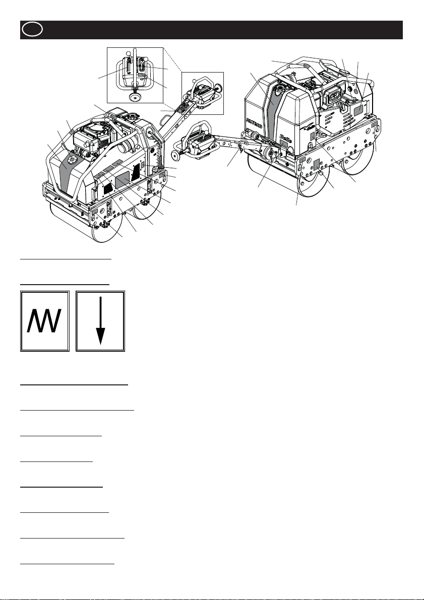
GB
5
17
10
18
1
9
Items 1 to 4 - Branding Decals
Branding Decals to identify the TDX Roller.
Item 5 - Vibration Lever Decal
Decals
13
7
6
21
8
9
25
3
24
23
22
Note:- Illustration shows the Yanmar L100N model.
20
19
2
14
9
12
4
9
16
15
Vibration
Engaged
Item 6 - Caution/Read Manual Decal
CAUTION! Please read the Operators Manual before using the machine.
Item 7 - Forward/Reverse Lever Decal
Lever to change the direction of the machine. F = Forward, R = Reverse, Ɣ = Neutral.
Item 8 - Maintenance Decal
Indicates the canopy can be removed for internal maintenance purposes.
Item 9 - Strapping Decal
Identi¿ es which areas can be used for strapping the machine to a hoist for lifting or strapping down during transportation.
Item 10 - Hot Surface Decal
CAUTION! Beware of hot surfaces around the Hydraulic Tank and Exhaust area.
Item 11 - Engine Oil Fill Decal
Indicates where to top-up the Engine Oil and where to check the Engine Oil level.
Item 12 - Hydraulic Oil Level Decal
Indicates the position of the Hydraulic Oil Gauge which shows the level of Hydraulic Oil within the tank.
Item 13 - Engine Oil Type Decal
Explains the type of oil which should be used to ¿ ll the engine.
Vibration
Disengaged
8
Page 9
Decals
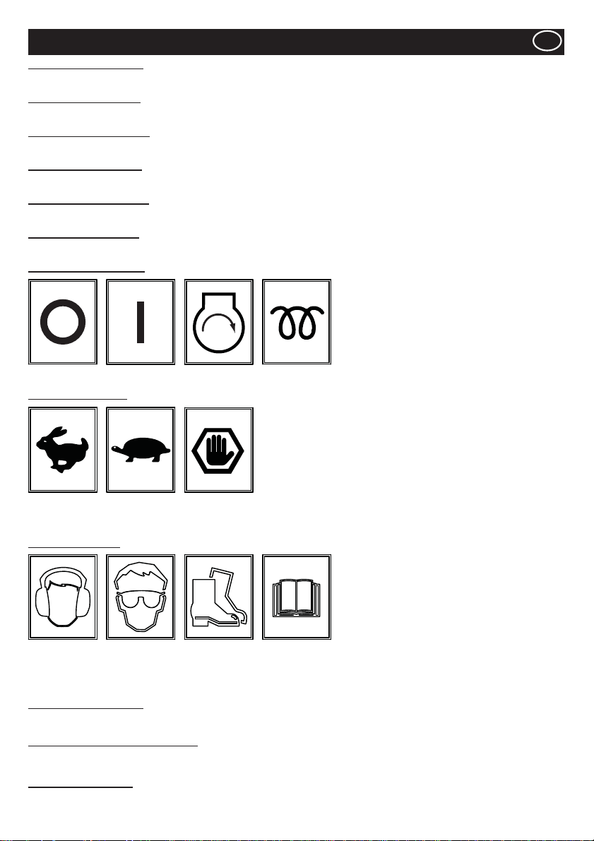
Item 14 - Water Drain Decal
If the forecasted ambient temperature is below freezing, the Water Tank must be drained using the Drain Plug.
Item 15 - Park Brake Decal
Shows the position of the Parking Brake. The Parking Brake must be applied when the machine is not in use.
Item 16 - Spraybar Tap Decal
Shows the position of the Spraybar Taps and also which Tap is for which Spraybar.
Item 17 - Diesel Only Decal
Engine must be ¿ lled with Diesel ONLY!
Item 18 - Hydraulic Oil Decal
Hydraulic Oil tank ¿ ller cap location.
Item 19 - Lifting Eye Decal
Lifting Eye for use with a Sling or Mechanical Hoist.
Item 20 - Ignition Key Decal
GB
OFF ON START
Item 21 - Throttle Decal
Max. RPM
Position
Idle
Position
Emergency
Stop
HEAT
(KUBOTA)
Position
Item 22 - Safety Decal
Wear Ear
Protection
Wear Eye
Protection
Wear
Protective
Footwear
Please
Read
Operators
Manual
Item 23 - Noise Level Decal
Guaranteed Sound Power Level of the machine in dB(A).
Item 24 - Exhaust Fumes Warning Decal
Engines emit carbon monoxide; operate only in well-ventilated areas.
Item 25 - Crushing Decal
CAUTION! Beware of mechanical components if guard is removed.
9
Page 10
GB
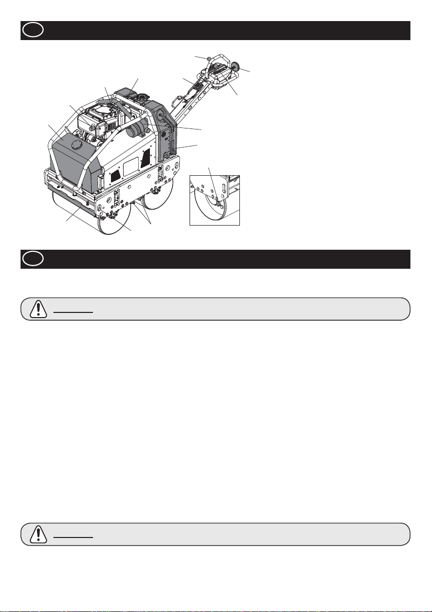
Machine Description
5
7
2
12
1
10
4
11
8
6
3
9
13
10
1. Hydraulic Oil Tank.
2. Lifting Eye.
3. Air Filter
4. Water Tank.
5. Forward / Reverse Lever.
6. Vibration Lever.
7. Safety Lever For Reverse Motion.
8. Throttle Lever
9. Water Level Gauge
10. Scraper Bars
11. Strapping Points.
12. Exhaust.
13. Parking Brake
Note:- Illustration shows the Yanmar L100N
model.
GB
For your own personal protection and for the safety of those around you, please read and ensure you fully understand the following
safety information. It is the responsibility of the operator to ensure that he/she fully understands how to operate this equipment safely.
If you are unsure about the safe and correct use of the TDX 650A Roller, consult your supervisor or ALTRAD Belle.
CAUTION
This machine must only be used for its intended purpose.
Ɣ
Ɣ
This machine must be operated only by well-trained personnel.
Ɣ
The owner of this machine must observe, and train the user of the machine to observe, the effective Labor Protection
Regulation in the country of application.
Ɣ
Use suitable lifting equipment to lift the machine.
Ɣ
This machine must be operated on the ground where stability is guaranteed. When working near the rim of excavated trenches, use
the machine properly so that the machine may not collapse or fall down.
If the surface to be compacted is on a slope, great care must be taken when controlling the machine’s direction of travel.
Ɣ
Always work up and down a slope, not across. If the machine is parked on a slope, always apply the Parking Brake Lever.
Cordon off the work area and keep members of the public and unauthorized personnel at a safe distance.
Ɣ
Personal Protective Equipment (PPE) must be worn by the operator whenever this equipment is being used (see Health & Safety)
Ɣ
Ɣ
Make sure you know how to safety switch this machine OFF before you switch it ON in case you get into dif¿ culty .
Always switch OFF the engine before servicing it.
Ɣ
During use the engine becomes very hot, allow the engine to cool before touching it.
Ɣ
Ɣ
Never leave the engine running and unattended.
Never remove or tamper with any guards ¿ tted, they are there for your protection. Always check guards for condition and
Ɣ
security. If any are damaged or missing, DO NOT USE THE MACHINE until the guard has been replaced or repaired.
Do not operate the machine when you are ill, feeling tired, or when under the inÀ uence of alcohol or drugs.
Ɣ
This machine is designed to eliminate the possible risks arising from the use of it. However, risks DO reside, and these residual
Ɣ
risks are not clearly recognizable, and may cause personal injury or property damage, and possible death. If such unpredictable
and unrecognizable risks become apparent, the machine must be stopped immediately, and operator or his supervisor must take
appropriate measure to eliminate such risks. It is sometimes necessary that the manufacturer must be informed of such event for
future counter measuring.
Fuel Safety
CAUTION
Ɣ Before refuelling, switch off the engine and allow it to cool.
Ɣ
When refuelling, DO NOT smoke or allow naked À ames in the area.
Ɣ
When refuelling, use proper funnel, and avoid spilling over the engine.
Ɣ
Spilt fuel must be made safe immediately, using sand. If fuel is spilt on your clothes, change them.
Ɣ
Store fuel in an approved, purpose made container away from heat and ignition source.
Improper maintenance can be hazardous. Read and Understand this section before you perform any
maintenance, service or repairs.
Fuel is À ammable. It may cause injury and property damage. Shut down the engine, extinguish all open
À ames and do not smoke while ¿ lling the fuel tank. Always wipe up any spilled fuel.
General Safety
10
Page 11
Health & Safety
Vibration
Some vibration from the compaction operation is transmitted through the handle to the operator’s hands. The Altrad Belle ‘TDX 650A’
has been speci¿ cally designed to reduce hand/arm vibration levels. Refer to Technical Data section for vibration levels and usage times
(recommended maximum daily exposure time). DO NOT exceed the maximum usage times.
PPE (Personal Protective Equipment).
Suitable PPE must be worn when using this equipment i.e. Safety Goggles, Gloves, Ear Defenders, Dust Mask and Steel Toe capped
footwear (with anti-slip soles for added protection). Wear clothing suitable for the work you are doing. Always protect skin from contact
with concrete.
Dust.
The compaction process can produce dust, which may be hazardous to your health. Always wear a mask that is suited to the type of
dust being produced.
Fuel.
Do not ingest fuel or inhale fuel vapors and avoid contact with your skin. Wash fuel splashes immediately. If you get fuel in your eyes,
irrigate with copious amounts of water and seek medical attention as soon as possible.
Exhaust Fumes.
Do not operate your TDX 650A Roller indoors or in a con¿ ned space, make sure the work area is adequately ventilated.
GB
WARNING
Pre start-up inspection.
The following Pre-start-up inspection must be performed before the start of each work session or after every four hours of use,
whichever is ¿ rst. Please refer to the service section for detailed guidance. If any fault is discovered, the ‘TDX 650A’ must not be used
until the fault is recti¿ ed.
1. Thoroughly inspect the machine for signs of damage.
2. Check hoses, ¿ ller openings, drain plugs and any other areas for signs of leakage. Fix any leaks before operating.
3. Check the engine oil level and top up as necessary.
3a. Place the machine on a level surface, and check the oil level of the engine.
3b. Remove the oil gauge, and observe that the oil is up to the rim of the ¿ ller port. Use proper engine oil with the proper viscosity
(Please see the SAE Service Grade Viscosity Chart in the Servicing section)
4. Check the engine fuel level and top up as necessary. Use clean fuel. Use of contaminated fuel may damage the fuel system.
5. Check the Air Filter is clean. Excessive dirt/dust accumulation within the ¿ lter element will cause erratic engine operation.
Clean the air ¿ lter element when it is contaminated. (See Servicing Section)
6. Check the function of Operators Controls. Make sure that the Drive lever, Vibration lever , Throttle Lever , Park Brake Lever , and the
safety device for the reverse motion moves smoothly.
7. Check the engine coolant level. Top up to ‘¿ ll’ level if required - KUBOTA ONLY!
Safe Disposal.
Instructions for the protection of the environment.
The machine contains valuable materials. Take the
discarded apparatus and accessories to the relevant
recycling facilities.
The exhaust fumes produced by this equipment are highly toxic and can kill!
Pre-start Checks
Environment
Component Material
Operator Handle Steel
Main Frame Steel
Hydraulic Oil Tank Steel
Water Tank Poly-Ethylene
Cover Poly-Ethylene
Hydraulic Pump Steel and Aluminium
Hydraulic Motor Steel
Engine Steel and Aluminium
Various parts Steel, Aluminium & Rubber
GB
GB
11
Page 12
GB
Start / Stop Procedure
CAUTION
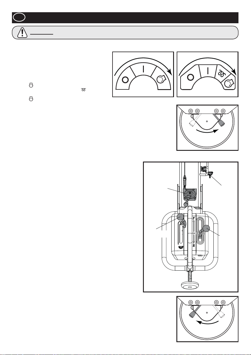
Before starting the engine, make sure that the Drive Lever is at Neutral, Vibration Lever is at OFF, and the Parking Lever is at ON
position.
1. Open the fuel tap at the engine.
2. Move the Throttle Lever on the Operation Handle to
the Full Throttle (Hare) position.
Start the Engine – Electric Start
3ai. YANMAR Start
3aii. KUBOTA - From cool, hold on Heat position for 10
secs.
Start
DO NOT crank for an extended period. Maximum 10 secs.
3b. After the engine has been started, make sure that the key is set to ON (I) position during
the operation. (Setting the Key Switch to OFF (0) position would not allow the generator to
charge the battery.)
Start the Engine – Manual Start
4a. Grasp the recoil starter handle.
4b. Pull the handle out slowly until you fee lstrong resistance.
4c. Slowly return the recoil starter to the initial position.
4d. Push the decompression lever down and then release it. The decompression lever will
automatically return to the original position when the engine starts.
4e. Grasp the recoil starter handle.
4f. Pull the handle all the way out with a strong and even motion. Use two hands if necessary.
4g. Slowly return the starter handle to the initial position.
4h. If the engine does not start, repeat the procedure from step 4b.
5. Move the Throttle Lever to LOW position, and let the engine run at idle
for a few minutes to warm up.
6. After the engine has warmed up, the machine is ready for operation.
7. Move the throttle lever to the high speed “H” position quickly to prevent
damage from occurring to the clutch. The “Full Throttle” position of this
machine has been preset at the factory to achieve optimum machine
performance.
DO NOT alter this setting since premature wear or tear can result, and
both engine and machine warranty will be automatically voided.
8. Move the Parking Brake Lever to the right to disengage it.
NOTE: Negligence to disengage the Parking Brake before attempting to
drive the machine forward or reverse will result in the severe
damage to the parking brake mechanism as well as the drive system.
9. Operators Control
9a. Throttle Lever
Always keep the Throttle Lever at High position during the operation.
DO NOT attempt to alter the travel speed by changing the engine
revolution.
9b. Drive Lever
Move the Drive Lever forward to drive the machine forward.
For reverse motion, move the lever backward.
9c. Vibration Lever
By shifting the Vibration Lever to ON position, the vibration mechanism
will be engaged, and produce the vibration.
10. Stopping the Engine
11. In preparation for stopping the engine, move the throttle lever
to LOW position.
12. Allow the engine to idle for 1-3 minutes.
13. Move the Throttle Lever to STOP position to stop the engine.
Then, set the Key Switch to “OFF” position. The buzzer will sound
when the Key Switch is set to ON while the engine is stopped.
14. Close the Fuel tap
15. Apply parking brake by swinging the Parking Brake Lever to the left.
position, and hold it until the engine starts.
Turn the Key Switch at the Throttle Lever to
position, and hold it until the engine starts.
DO NOT let your hands off from the Starting Handle during the Starting procedures.
YANMAR KUBOTA
Turn the Key Switch at the Throttle Lever to
THROTTLE
LEVER
VIBRATION
LEVER
DISENGAGE
ENGAGE
KEY
SWITCH
DRIVE
LEVER
12
Page 13

Operating the TDX 650A Roller
Ɣ Having carried out the checks listed in the ‘pre start’ section, you may start the engine.
The ALTRAD Belle TDX 650A Roller is ¿ tted with a centrifugal clutch; this allows the engine to run at idle without driving the
Hydraulic pump.
Ɣ As the engine speed is increased the clutch will engage and the engine will drive the Hydraulic Pump to send the hydraulic
power to drive the drums, and to drive the vibration mechanism as well. To avoid any damage to the centrifugal clutch, move
the throttle lever quickly from L to H position. For correct operation, the engine speed should be set to maximum during the
compaction operation
Ɣ Avoid operating the machine on a fully compacted, hard, or non-yielding surface. Otherwise, the bearings and other mechanical
components will be damaged, and the life of the machine will be greatly reduced.
Ɣ When working on a steep slope, pay extra care in operating the machine so that the machine roll down the slope.
Always work up or down the slop. Do not work across the slope. If the machine is parked on a slope, always apply the Parking
Brake Lever.
Ɣ When the machine is going in reverse, make sure not to stand behind the Operation Handle. Always walk along the Operation
Handle and face toward the direction of travel.
Ɣ Lifting
Where it is necessary to use lifting equipment to position the TDX 650A, make sure the lifting equipment has a WLL (Working Load
Limit) suitable for the machine’s weight (see T ecnical Data table). Attach suitable chains or slings ONL Y to the lifting points provided
at the centre of the machine (Lifting Eye) or at each corner of the machine (Strapping Points).
Ɣ TRANSPORTATION
Transportation on a vehicle.
Make sure to lock the Handle and use proper slopes of suf¿ cient width, length, and strength on loading to and unloading from
the vehicle.
Ɣ Apply the parking brake, and tie the machine ¿ rmly to the vehicle during the transportation.
GB
Servicing
Maintenance
The ALTRAD Belle TDX 650A is designed to give many years of trouble free operation. It is, however, important that the simple
regular maintenance listed in this section is carried out. It is recommended that an approved ALTRAD Belle dealer carries out all major
maintenance and repairs. Always use genuine ALTRAD Belle replacement parts, the use of spurious parts may void your warranty.
Before any maintenance is carried out on the machine, switch off the engine and remove Key from the Key Switch
Always set the machine on level ground to ensure any À uid levels will be correctly read. Only use recommended oils (see page 15).
Servicing the Engine
Service the engine according to the engine manufacturer’s speci¿ cations.
Refer to the engine operation and maintenance manual.
Note: When the Maintenance Cover has been removed, ensure that all Bolts are securely fastened when re-¿ tting. DO NOT restart the
machine with guards removed.
Maintenance: Every 8 hours or daily
1. Check for loose bolts and nuts, retighten if necessary.
2. Check and clean the air ¿ lter element, re-lube the element in accordance with the engine manufacturer’s recommendations. If
operating conditions are unusually dusty and severe, ¿ lter element cleaning should be done more frequently.
3. Check Engine Oil Level before operation.
Maintenance: After ¿ rst 50 hours and every 200 hours thereafter
1. Change the Engine Oil - see procedure on page 15.
GB
13
Page 14
GB
Maintenance: Every 50 hours or weekly
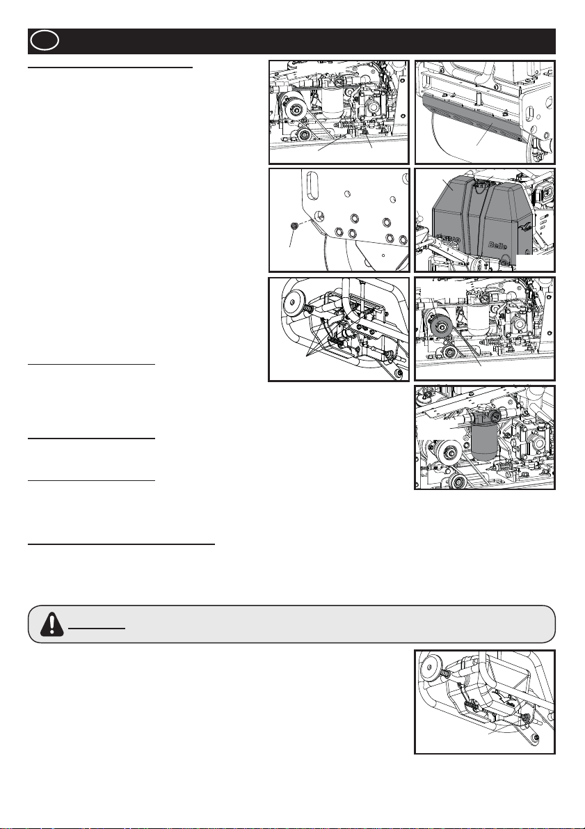
1. Check for the tension of Drive Belt
1a. Loosen four bolts, which ¿ xes the Pump Bracket, and
turn the Adjust Bolt until proper tension is achieved.
The belt should deÀ ect by 5mm at the center between
Centrifugal clutch and pump pulley.
1b. Tighten four bolts at the Pump Bracket. When the belt
is worn out or cracked, renew the belt.
2. Adjust the clearance of Scraper
2a. Remove the Scraper, and wipe of all the dirt, mud, and
asphalt.
2b. Re¿ t the Scraper to the Scraper Bracket and ¿ x it with
suitable clearance (1mm) from the drum.
3. Water Tank
3a. Drain all the water, and clean the inside of the tank
using a hose
4. Sprinkler Nozzle
4a. Remove the Cap from the nozzle, and clean the inside
of Sprinkler Nozzle.
5. Moving Parts
Feed grease to the Rod End of the Drive/Vibration Cable.
5a.
5b.
Re-Grease the Greasing Points in the Operation Handle.
5c. Grease the Vibrator Shaft
Maintenance: Every 100 hours
1. Vibration Clutch Mechanism
1a. Check to con¿ rm that the Vibration Clutch Mechanism
works properly.
1b. Feed grease to the moving part.
1c. Check the condition of V-belt. When it is worn out or cracked, renew the belt.
Maintenance: Every 500 hours
1. Replace the Hydraulic Oil Filter Element at every 500 hours of operation.
Use Genuine Filter element.
Maintenance: Every 800 hours
1. Replace the Hydraulic Oil. Flush off the tank before supplying the new Hydraulic Oil.
To vent the air in the hydraulic system, leave the Tank Cover open, and run the engine at
its maximum speed without operating the Drive Lever and Vibration Lever for 10 minutes.
Then, re¿ t the Tank Cover.
Adjusting The Neutral Setting Of Drive Lever
The neutral position of the Drive Lever may be shifted due to the vibration or wear of the drive cables. To adjust the Neutral Setting,
follow the instructions below;
1. Place the machine on a level surface.
2. Make sure that the engine is turned off.
3. Remove the Nut which ¿ x the Rod End of Drive Cable to the Drive Lever.
Do not attempt to start the engine when this nut is off its position. Machine may move suddenly and
WARNING
4. Loosen the Lock Nut at the Rod End.
5. Turn the Rod End either clockwise or counterclockwise depending upon the direction of
shifted neutral position.
6. Re¿ t the Rod End to the Drive Wire, and secure it with nut.
7. Start the engine, and increase the engine revolution to maximum. Observe to see if the
neutral position has been properly adjusted.
8. If not, stop the engine, remove the nut, and repeat the procedure 5 to 7 until the neutral
position is properly set.
9. When the neutral position is correctly adjusted, apply Loctite to the Nut, which ¿ x the Rod
End, and tighten it. Then, tighten the Lock Nut at the rod end.
irrationally without the capability of being controlled with the Drive Lever, which may cause severe injury or
property damage.
Servicing
DRIVE BELT
BELT ADJUSTER
SPRINKLER
CAP
GREASING
POINTS
BRACKET BOLT
SCRAPER
TANK
VIBRATION
CLUTCH
FILTER
ELEMENT
LOCK NUT
V-BELT
CAP
DRAIN
PLUG
14
Page 15
Servicing
GB
Hydraulic Oil
Ɣ Total EP32, Shell Tellus T37, MOBIL DTE15 or ESSO Unipower, XL46.
Engine Oil
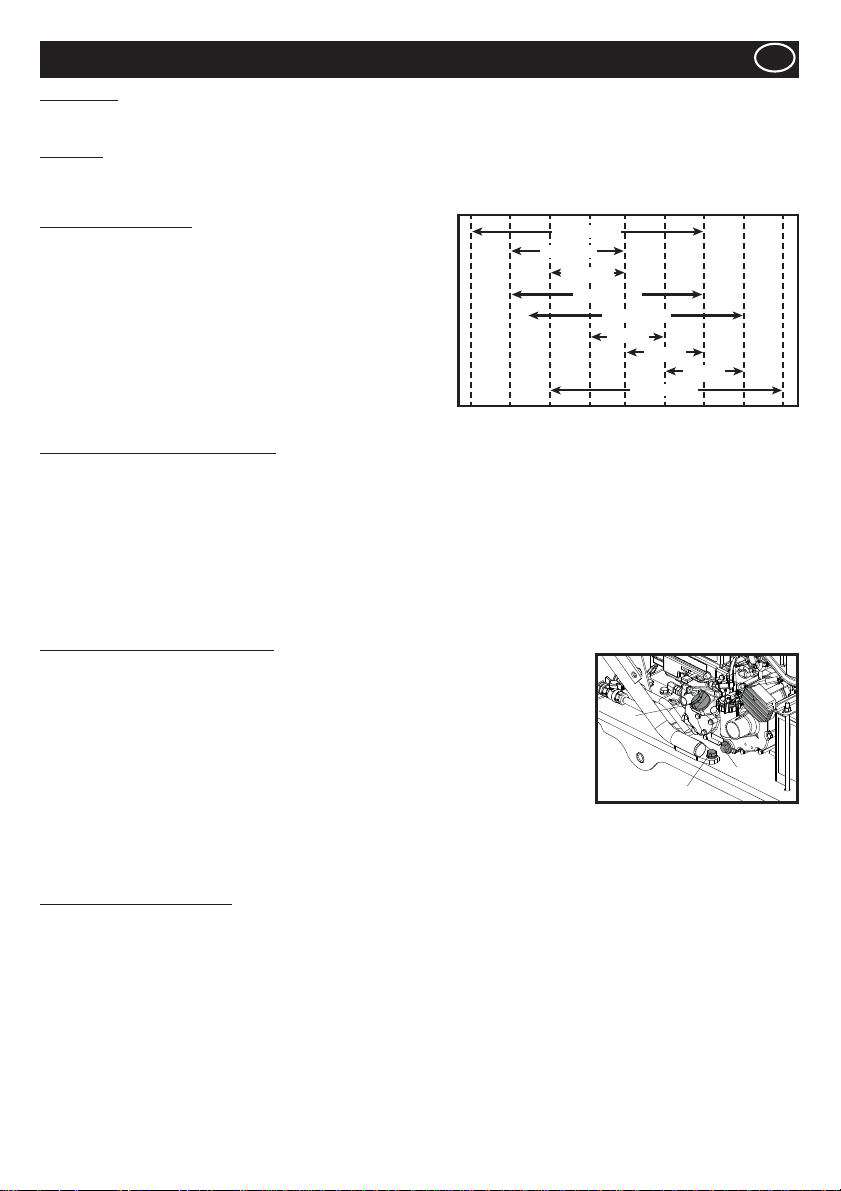
Select the appropriate engine oil viscosity based on the ambient temperature and use the SAE Service Grade Viscosity Chart below.
This machine is ¿ lled with SAE 15W-40 at the factory.
Engine Oil Speci¿ cations
Use an engine oil that meets or exceeds the following guidelines
and classi¿ cations:
Service Categories
Ɣ API Service Categories CD or higher.
Ɣ ACEA Service Categories E-3, E-4 and E-5
Ɣ JASO Service Category DH-1
De¿ nitions
Ɣ API Classi¿ cation (American Petroleum Institute)
Ɣ ACEA Classi¿ cation (Association des Constructeurs Européens
d’automobilies)
Ɣ JASO (Japanese Automobile Standards Organisation)
30°F
(22°C)
(-20°C)
-4°F
SAE 10W
14°F
(-10°C)
SAE 5W-30
SAE 20W
SAE 10W-30
32°F
(0°C)
SAE 15W-40
SAE 20
SAE 30
SAE 20W-50
50°F
68°F
(10°C)
(20°C)
SAE 40
86°F
(30°C)
104°F
(40°C)
122°F
(50°C)
Engine Oil Change Procedure - Yanmar
1. Ensure the Roller is on a level surface and the operating handle in the storage position. Apply the Park Brake.
2. Loosen the nut on the underside of the oil ¿ ll / drain plug. NOTE:- DO NOT remove the plug at this stage.
3. Slide the hose from the side panel.
4. Remove 4 x M8 Set Screws using a 13mm spanner. Remove side panel.
5. Bring the hose out of the chassis, remove the plug and drain the oil into a container.
6. Re-¿ t the side panel using a 13mm spanner and slide the oil ¿ ll / drain hose back into the slot in the panel. Tighten the nut to secure
to the side panel but leave the plug removed.
7. Using a funnel, pour oil into the ¿ ller hose. Care must be taken whilst ¿ lling to ensure capacity is not exceeded. Use a dipstick on
left-hand side of the engine to check oil level.
8. Re-¿ t oil ¿ ll / drain plug.
9. Check that the machine functions correctly.
Engine Oil Change Procedure - Kubota
1. Place the Operating Handle in the storage position and apply the Park Brake.
2. Mount the Roller onto 40mm blocks, ensuring the Roller is tilting towards the Drain Plug side.
3. Remove 4 x M8 Set Screws from the Side Guard using a 13mm Socket. Remove Side Guard.
4. Using a 19mm Spanner remove the 1 x M12 Bolt (Item 1) from the Roller Frame.
5. Using a 17mm Spanner remove the Drain Plug / Oil Filter (Item 2) from the Engine and allow
the Oil to drain into a suitable container.
6. Wash out the Drain Plug / Oil Filter with Light Oil and re-place into the Engine.
Tighten to 50Nm.
7. Re-¿ t the 1 x M12 Bolt into the Frame using a 19mm Spanner and tighten to 90Nm.
8. Remove the Roller from the 40mm blocks. Ensure the Roller is now on a level surface.
9. Remove the Oil Filler Cap from the Engine (Item 3) and pour Oil into the Engine (1.3 Litres)
10. Re-¿ t the Oil Filler Cap.
11. Re-¿ t Side Guard to the Roller with 4 x M8 Set Screws using a 13mm Socket. Tighten to 28Nm.
12. Release the Park Brake and lower the Operating Handle.
13. Check that the machine functions correctly.
3
2
1
Battery Replacement Procedure
1. Remove the 4 x Bolts from the side guard using a 13mm Socket and remove the side guard. Save the fasteners.
2. Using an 11mm spanner, remove the earth cable from the battery then remove the positive cable from the battery.
3. Remove the battery clamp and pad. Remove 2 x nuts and 2 x washers using a 13mm spanner.
4. Remove the long battery stud and washer using a 13mm spanner.
5. Remove 2 x bolts from the regulator using 10mm socket.
6. Remove bracket which was behind the regulator using a 10mm socket. Ensure not to lose the spacer from behind the bracket.
7. Move the À exible cable retaining strap and pull the wires out.
8. Slide the battery out and replace with the new battery.
9. Put the wires into back into place and secure in place with the cable retaining strap.
10. Re-¿ t bracket and spacer and tighten to 12Nm.
11. Re-¿ t the 2 x bolts into the regulator and tighten to 12Nm.
12. Re-¿ t the battery stud and washer and tighten to 28Nm.
13. Re-¿ t the battery clamp and pad using 13mm spanner. Tighten the nut to ensure that 8mm of thread is exposed.
14. Attach the positive cable to the battery followed by the earth cable.
15. Re-¿ t the side guard. Tighten the 4 x bolts to 28Nm.
15
Page 16
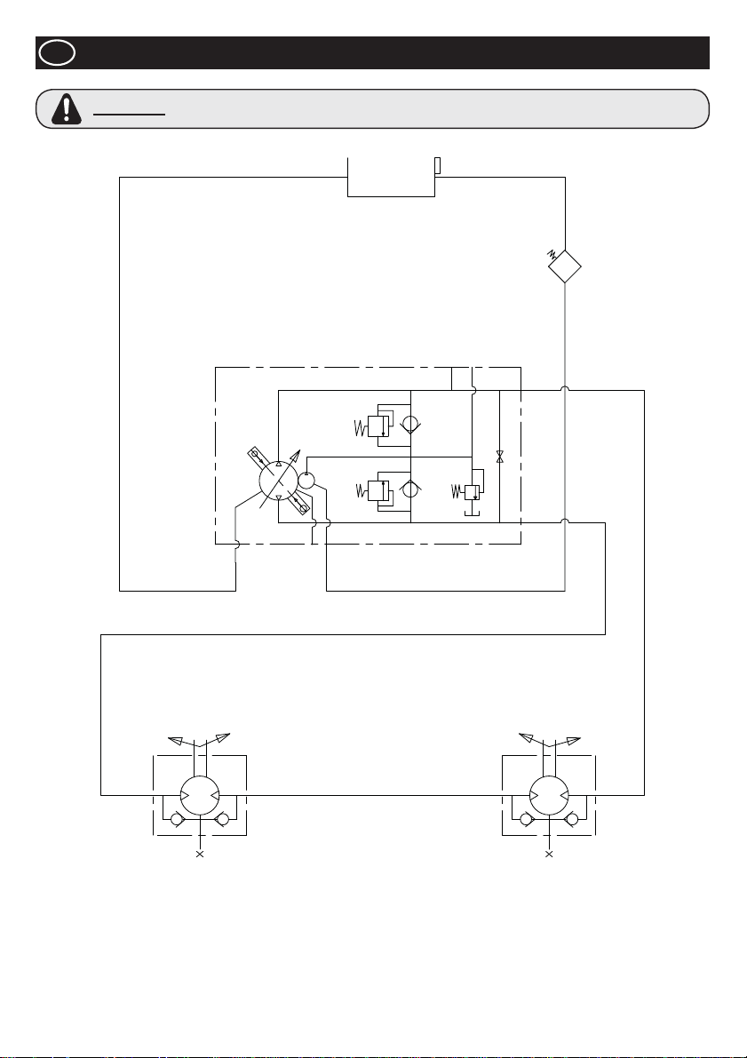
GB
Hydraulic Circuit
WARNING
If carrying out any repairs on the Hydraulic Circuit the tank ¿ ller cap must be loosened to ensure the
system is not pressurised.
16
Page 17
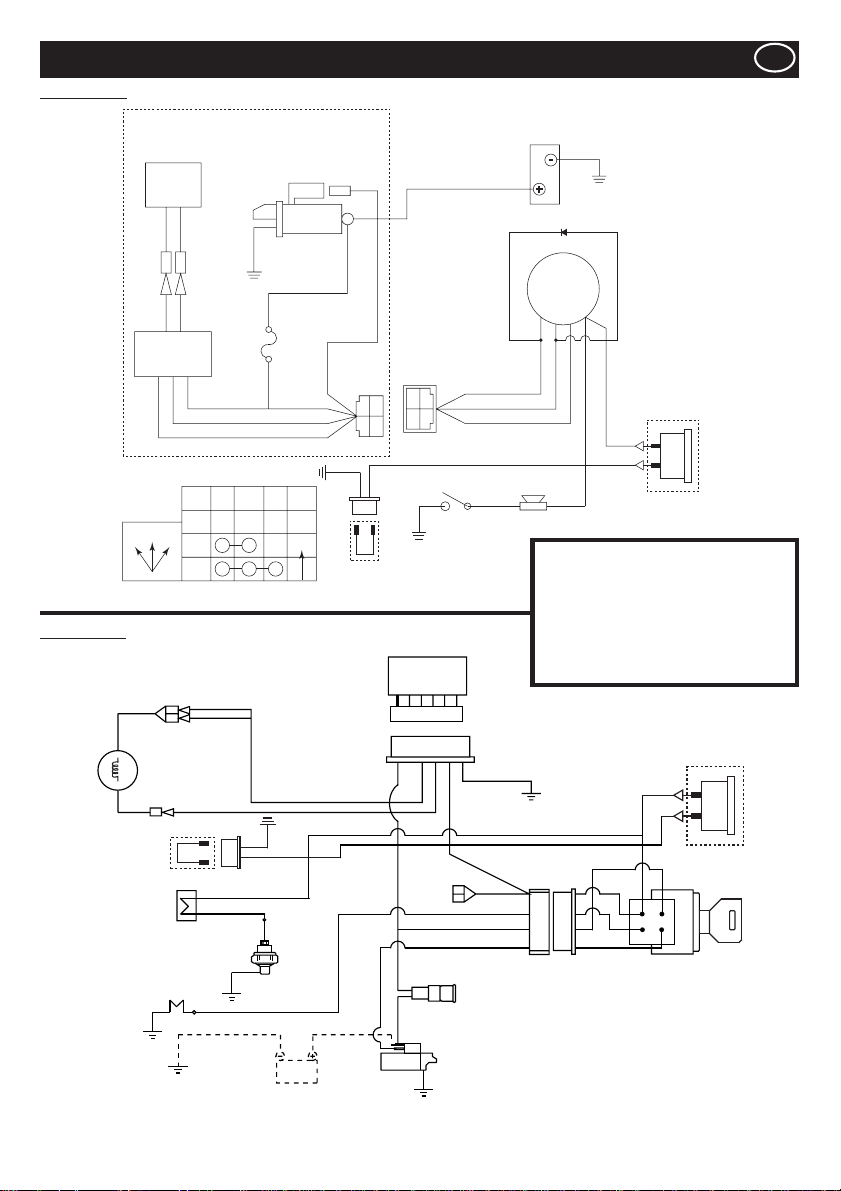
Yanmar L100N
Wiring Diagram
GB
Kubota EA330
12V - 15A
Dynamo
G/W G/W
CB104 CB104
CA104 CA104
G/W G/W
Regulator
HOW KEY SWITCH FUNCTION
OFF
OFF12
1
2
Y
Starter Motor
DC12v 0.8kW
W
JAS0
D601
20T
IG BAT ST NOTE
AUTO
AV2 0
Switch
AV1.25
AV1.25
AV1.25
AV2 0
G
W
Siren
M8
Screw
R
7323-2446
RY
B
B
Hour Clock
Link Wire
BR
G
W
YAZAKI NO.
7322-2446
WG
Oil Pressure
Ground
R
YAZAKI NO.
W
G
Y
Ground
Battery
Diode
Key Switch
BAT
(15)
IG
ST
(75)
(50)
(30)
Y
R
Y
Hour Clock
Option
Inventory
G = Green IG = Ignition
W = White BAT = Battery
Y = Yellow ST = Start
R = Red BK = Black
Regulator
BL = Blue SB = Sky Blue
OR = Orange BR = Brown
Y
SBGBK
SB
R
Fan
Dynamo
Hour Clock
Link Wire
R
B
Buzzer
Oil Switch
Glow Plug
BK/R
SB
BK
Y
BR
Battery
R
Y
BR
BR
Y
Y
Y
W
W
BK/R
R
BK/W
Y
G
R
Hour Clock
Option
Starter Switch
R
Fuse
Starter
17
Page 18
GB
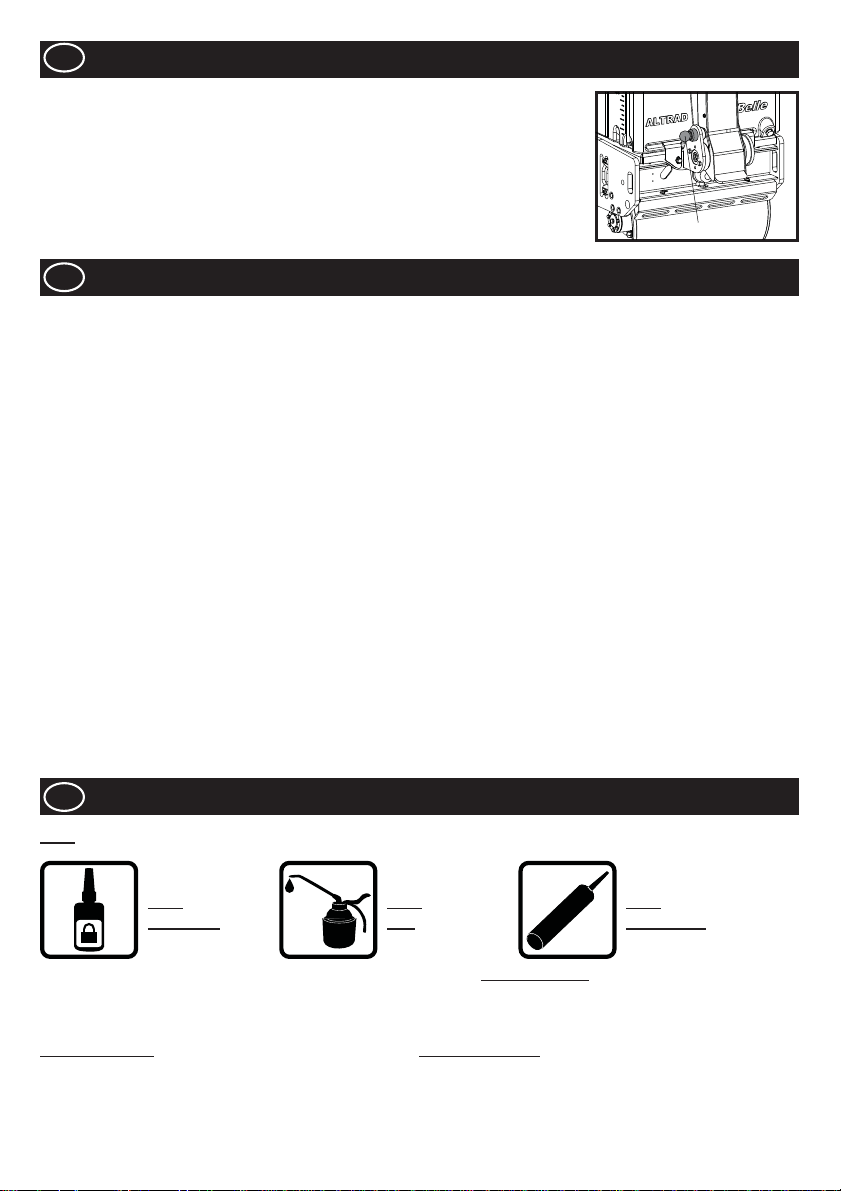
1. For long-term storage, empty the fuel from the Fuel Tank by either sucking the remaining fuel
out from the Fuel Inlet port or from the Fuel Filter after the ¿ lter cup has been removed.
2. Clean the Air Cleaner Element.
3. Clean-up the oil and dust accumulation on all rubber parts.
4. Clean the base plate and apply a light coating of oil to prevent rust formation.
5. Cover the machine and store it in a dry place.
6. The Operation Handle can be stood up for storage. Pull the Stopper, and raise the handle.
Make sure that the Stopper securely holds the Operation Handle.
Long Term Storage
LATCH
GB
Your new ALTRAD Belle TDX 650A Roller is warranted to the original purchaser for a period of one-year (12 months) from the original
date of purchase.
The Altrad Belle warranty is against defects in design, materials an workmanship.
The following are not covered under the Altrad Belle warranty:
1. Damage caused by abuse, misuse, dropping or other similar damage caused by or as a result of failure to follow assembly,
operation or user maintenance instructions.
2. Alterations, additions or repairs carried out by persons other than Altrad Belle or their recognised agents.
3. Transportation or shipment costs to and from Altrad Belle or their recognised agents, for repair or assessment against a
warranty claim, on any machine.
4. Materials and/or labour costs to renew, repair or replace components due to fair wear and tear.
The following components are not covered by warranty.
· Engine air ¿ lter
Altrad Belle and/or their recognised agents, directors, employees or insurers will not be held liable for consequential or other damages,
losses or expenses in connection with or by reason of or the inability to use the machine for any purpose.
Warranty Claims
All warranty claims should ¿ rstly be directed to Altrad Belle, either by telephone, by Fax, by Email, or in writing.
For warranty claims:
Altrad Belle Warranty Department,
Sheen, Nr. Buxton,
Derbyshire
SK17 0EU
England.
GB
Spare Parts Information
Warranty
KEY
USE
LOCTITE
For information regarding Spare Parts availability for this machine, please visit www.Belle247.com or contact the ALTRAD Belle using
the following contact details:-
# - Colour Option 1 ## - Colour Option 2
Part No. + S = Orange (Eg. 981/05100S) Part No. + GR = Grey (Eg. 981/03200GR)
Part No. + G = Green Part No. + GR2 = Quartz Grey
Part No. + B1 = Blue Part No. + BL = Black
Part No. + R1 = Red Part No. + W = White
Part No. + Y = Yellow
Part No. + Y2 = Yellow
USE
OIL
ILICONE
S
USE
SILICONE
18
Page 19
How To Use This Manual
This manual has been written to help you operate and service the TDX 650A Roller safely. This manual is intended for dealers and
operators of the TDX 650A Roller .
Foreword
The ‘Machine Description’ section helps you to familiarise yourself with the machine’s layout and controls.
The ‘Environment’ section gives instructions on how to handle the recycling of discarded apparatus in an environmentally friendly way.
The ‘General Safety’ and ‘Health and Safety’ sections explain how to use the machine to ensure your safety and the safety of the
general public.
The ‘Operating Instructions’ section helps you with the setting up and use of the machine.
The ‘Trouble Shooting Guide’ helps you if you have a problem with your machine.
The ‘Service & Maintenance’ section is to help you with the general maintenance and servicing of your machine.
Directives with regard to the notations.
Text in this manual to which special attention must be paid are shown in the following way:
CAUTION
The product can be at risk. The machine or yourself can be damaged or injured if procedures are not
carried out in the correct way.
WARNING
The life of the operator can be at risk.
WARNING
WARNING
KNOW how to safely use the unit’s controls and what you must do for safe maintenance. (NB Be sure that you know how to switch the
machine off before you switch on, in case you get into dif¿ culty.)
ALWAYS wear or use the proper safety items required for your personal protection. If you have ANY QUESTIONS about the safe use
or maintenance of this unit, ASK YOUR SUPERVISOR OR CONTACT: ALTRAD BELLE (UK): +44 (0) 1298 84606
Before you operate or carry out any maintenance on this machine YOU MUST READ and STUDY
this manual.
Contents
How to use this manual ............................................................................................................................................................................ 19
Warning ....................................................................................................................................................................................................19
Technical Data .......................................................................................................................................................................................... 20
Decals ...............................................................................................................................................................................................21 - 22
Machine Description .................................................................................................................................................................................23
General Safety .........................................................................................................................................................................................23
Health and Safety ..................................................................................................................................................................................... 24
Pre-Start Checks ......................................................................................................................................................................................24
Environment .............................................................................................................................................................................................24
Start & Stop Procedure ............................................................................................................................................................................ 25
Operating the TDX Roller .........................................................................................................................................................................26
Service & Maintenance .....................................................................................................................................................................26 - 28
Hydraulic Circuit ....................................................................................................................................................................................... 29
Wiring Diagram ......................................................................................................................................................................................... 30
Long Term Storage ................................................................................................................................................................................... 31
Warranty ...................................................................................................................................................................................................31
Spare Parts Information ........................................................................................................................................................................... 31
Altrad Belle reserves the right to change machine speci¿ cation without prior notice or obligation.
19
Page 20
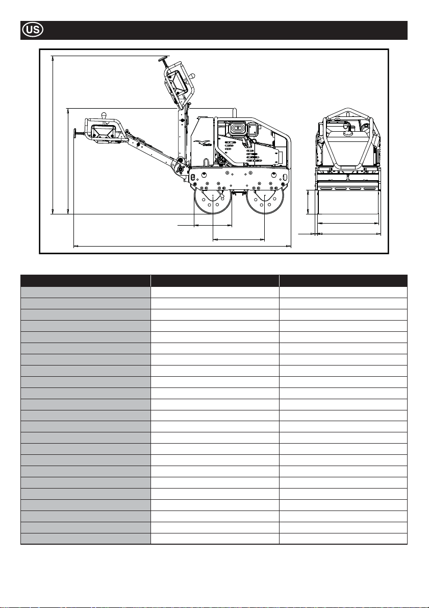
Technical Data
J
B
G
D
A
Model TDX 650A Yanmar L100N TDX 650A Kubota EA330
Weight* - lbs 1488 1508
A - Overall Length - in 91.2 91.2
B - Overall Height - in 44.8 44.8
C - Wheel Base - in 22 22
D - Drum Diameter - in 15.8 15.8
E - Drum Width - in 25.5 25.5
F - Overall Width - in 27.7 27.7
G - Curb Clearance - in 10.1 10.1
H - Lateral Overhang - in 11
J - Height at Storage - in 66 66
Travel Speed (F’wrd) - m/m (km/h) 0 - 70 (0 - 4.2) 0 - 70 (0 - 4.2)
Travel Speed (Rev) - m/m (km/h) 0 - 38 (0 - 2.3) 0 - 38 (0 - 2.3)
Vibration Frequency - v.p.m 3300 3300
Centrifugal Force - kN 16 16
Water Tank Capacity - Gal 17.2 17.2
Oil Tank Capacity - Gal 4.2 4.2
Engine YANMAR L100N KUBOTA EA330
Type 4-Cycle Air-Cooled 4-Cycle Water-Cooled
Fuel Diesel Diesel
Fuel Tank Capacity - Gal 1.4 1.28
Rated Output - Hp (kW) 9 (6.6) 5.9 (4.4)
Max. Output - Hp (kW) 10 (7.4) 6.9 (5.2)
Starting System Electric (with Recoil Start back-up option) Electric
* Weight is without any water in the Water Tank. Water in Tank = 17.2 gals = 143lbs
C
H
E
F
20
Page 21
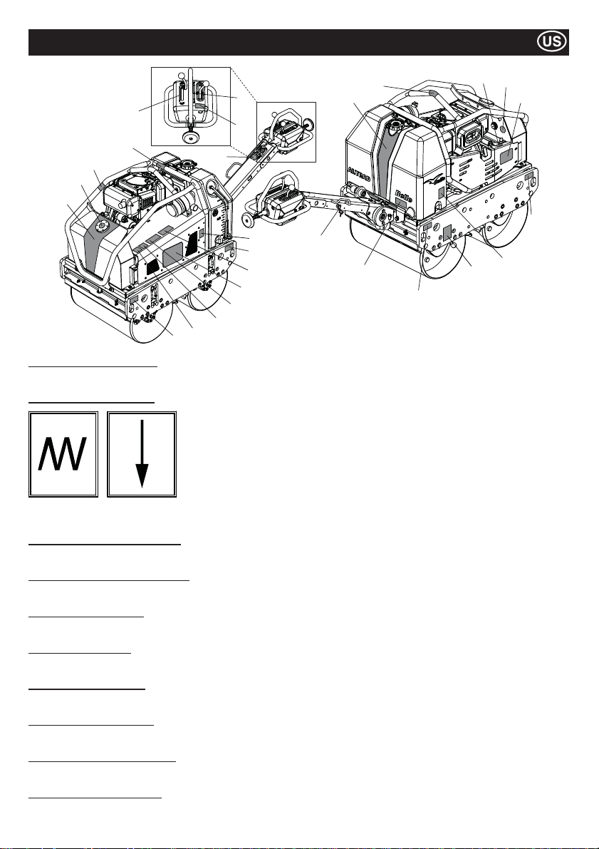
5
17
10
18
1
9
Items 1 to 4 - Branding Decals
Branding Decals to identify the TDX Roller.
Item 5 - Vibration Lever Decal
Decals
13
7
6
21
8
9
25
3
24
23
22
Note:- Illustration shows the Yanmar L100N model.
20
19
2
14
9
12
4
9
16
15
Vibration
Engaged
Item 6 - Caution/Read Manual Decal
CAUTION! Please read the Operators Manual before using the machine.
Item 7 - Forward/Reverse Lever Decal
Lever to change the direction of the machine. F = Forward, R = Reverse, Ɣ = Neutral.
Item 8 - Maintenance Decal
Indicates the canopy can be removed for internal maintenance purposes.
Item 9 - Strapping Decal
Identi¿ es which areas can be used for strapping the machine to a hoist for lifting or strapping down during transportation.
Item 10 - Hot Surface Decal
CAUTION! Beware of hot surfaces around the Hydraulic Tank and Exhaust area.
Item 11 - Engine Oil Fill Decal
Indicates where to top-up the Engine Oil and where to check the Engine Oil level.
Item 12 - Hydraulic Oil Level Decal
Indicates the position of the Hydraulic Oil Gauge which shows the level of Hydraulic Oil within the tank.
Item 13 - Engine Oil Type Decal
Explains the type of oil which should be used to ¿ ll the engine.
Vibration
Disengaged
21
Page 22
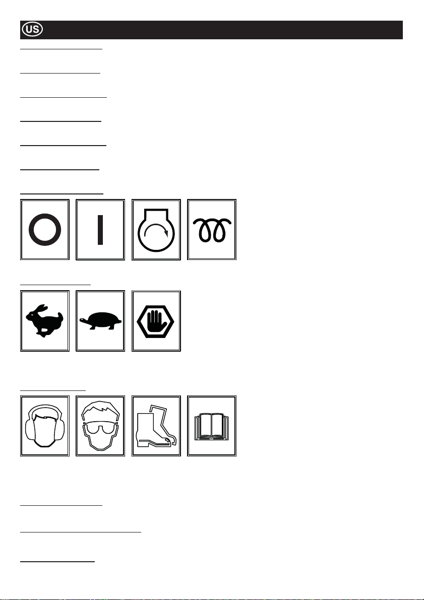
Decals
Item 14 - Water Drain Decal
If the forecasted ambient temperature is below freezing, the Water Tank must be drained using the Drain Plug.
Item 15 - Park Brake Decal
Shows the position of the Parking Brake. The Parking Brake must be applied when the machine is not in use.
Item 16 - Spraybar Tap Decal
Shows the position of the Spraybar Taps and also which Tap is for which Spraybar.
Item 17 - Diesel Only Decal
Engine must be ¿ lled with Diesel ONLY!
Item 18 - Hydraulic Oil Decal
Hydraulic Oil tank ¿ ller cap location.
Item 19 - Lifting Eye Decal
Lifting Eye for use with a Sling or Mechanical Hoist.
Item 20 - Ignition Key Decal
OFF ON START
Item 21 - Throttle Decal
Max. RPM
Position
Idle
Position
Emergency
Stop
HEAT
(KUBOTA)
Position
Item 22 - Safety Decal
Wear Ear
Protection
Wear Eye
Protection
Wear
Protective
Footwear
Please
Read
Operators
Manual
Item 23 - Noise Level Decal
Guaranteed Sound Power Level of the machine in dB(A).
Item 24 - Exhaust Fumes Warning Decal
Engines emit carbon monoxide; operate only in well-ventilated areas.
Item 25 - Crushing Decal
CAUTION! Beware of mechanical components if guard is removed.
22
Page 23
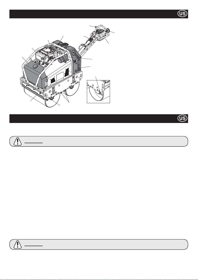
Machine Description
5
7
2
12
1
10
4
11
8
6
3
9
13
10
1. Hydraulic Oil Tank.
2. Lifting Eye.
3. Air Filter
4. Water Tank.
5. Forward / Reverse Lever.
6. Vibration Lever.
7. Safety Lever For Reverse Motion.
8. Throttle Lever
9. Water Level Gauge
10. Scraper Bars
11. Strapping Points.
12. Exhaust.
13. Parking Brake
Note:- Illustration shows the Yanmar L100N
model.
General Safety
For your own personal protection and for the safety of those around you, please read and ensure you fully understand the following
safety information. It is the responsibility of the operator to ensure that he/she fully understands how to operate this equipment safely.
If you are unsure about the safe and correct use of the TDX 650A Roller, consult your supervisor or ALTRAD Belle.
CAUTION
Ɣ This machine must only be used for its intended purpose.
Ɣ
This machine must be operated only by well-trained personnel.
Ɣ
The owner of this machine must observe, and train the user of the machine to observe, the effective Labor Protection
Regulation in the country of application.
Ɣ
Use suitable lifting equipment to lift the machine.
Ɣ
This machine must be operated on the ground where stability is guaranteed. When working near the rim of excavated trenches, use
the machine properly so that the machine may not collapse or fall down.
If the surface to be compacted is on a slope, great care must be taken when controlling the machine’s direction of travel.
Ɣ
Always work up and down a slope, not across. If the machine is parked on a slope, always apply the Parking Brake Lever.
Cordon off the work area and keep members of the public and unauthorized personnel at a safe distance.
Ɣ
Personal Protective Equipment (PPE) must be worn by the operator whenever this equipment is being used (see Health & Safety)
Ɣ
Ɣ
Make sure you know how to safety switch this machine OFF before you switch it ON in case you get into dif¿ culty.
Always switch OFF the engine before servicing it.
Ɣ
During use the engine becomes very hot, allow the engine to cool before touching it.
Ɣ
Ɣ
Never leave the engine running and unattended.
Never remove or tamper with any guards ¿ tted, they are there for your protection. Always check guards for condition and
Ɣ
security. If any are damaged or missing, DO NOT USE THE MACHINE until the guard has been replaced or repaired.
Do not operate the machine when you are ill, feeling tired, or when under the inÀ uence of alcohol or drugs.
Ɣ
This machine is designed to eliminate the possible risks arising from the use of it. However, risks DO reside, and these residual
Ɣ
risks are not clearly recognizable, and may cause personal injury or property damage, and possible death. If such unpredictable
and unrecognizable risks become apparent, the machine must be stopped immediately, and operator or his supervisor must take
appropriate measure to eliminate such risks. It is sometimes necessary that the manufacturer must be informed of such event for
future counter measuring.
Fuel Safety
CAUTION
Ɣ Before refuelling, switch off the engine and allow it to cool.
Ɣ
When refuelling, DO NOT smoke or allow naked À ames in the area.
Ɣ
When refuelling, use proper funnel, and avoid spilling over the engine.
Ɣ
Spilt fuel must be made safe immediately, using sand. If fuel is spilt on your clothes, change them.
Ɣ
Store fuel in an approved, purpose made container away from heat and ignition source.
Improper maintenance can be hazardous. Read and Understand this section before you perform any
maintenance, service or repairs.
Fuel is À ammable. It may cause injury and property damage. Shut down the engine, extinguish all open
À ames and do not smoke while ¿ lling the fuel tank. Always wipe up any spilled fuel.
23
Page 24
Health & Safety
Vibration
Some vibration from the compaction operation is transmitted through the handle to the operator’s hands. The Altrad Belle ‘TDX 650A’
has been speci¿ cally designed to reduce hand/arm vibration levels. Refer to Technical Data section for vibration levels and usage times
(recommended maximum daily exposure time). DO NOT exceed the maximum usage times.
PPE (Personal Protective Equipment).
Suitable PPE must be worn when using this equipment i.e. Safety Goggles, Gloves, Ear Defenders, Dust Mask and Steel Toe capped
footwear (with anti-slip soles for added protection). Wear clothing suitable for the work you are doing. Always protect skin from contact
with concrete.
Dust.
The compaction process can produce dust, which may be hazardous to your health. Always wear a mask that is suited to the type of
dust being produced.
Fuel.
Do not ingest fuel or inhale fuel vapors and avoid contact with your skin. Wash fuel splashes immediately. If you get fuel in your eyes,
irrigate with copious amounts of water and seek medical attention as soon as possible.
Exhaust Fumes.
Do not operate your TDX 650A Roller indoors or in a con¿ ned space, make sure the work area is adequately ventilated.
WARNING
The exhaust fumes produced by this equipment are highly toxic and can kill!
Pre-start Checks
Pre start-up inspection.
The following Pre-start-up inspection must be performed before the start of each work session or after every four hours of use,
whichever is ¿ rst. Please refer to the service section for detailed guidance. If any fault is discovered, the ‘TDX 650A’ must not be used
until the fault is recti¿ ed.
1. Thoroughly inspect the machine for signs of damage.
2. Check hoses, ¿ ller openings, drain plugs and any other areas for signs of leakage. Fix any leaks before operating.
3. Check the engine oil level and top up as necessary.
3a. Place the machine on a level surface, and check the oil level of the engine.
3b. Remove the oil gauge, and observe that the oil is up to the rim of the ¿ ller port. Use proper engine oil with the proper viscosity
(Please see the SAE Service Grade Viscosity Chart in the Servicing section)
4. Check the engine fuel level and top up as necessary. Use clean fuel. Use of contaminated fuel may damage the fuel system.
5. Check the Air Filter is clean. Excessive dirt/dust accumulation within the ¿ lter element will cause erratic engine operation.
Clean the air ¿ lter element when it is contaminated. (See Servicing Section)
6. Check the function of Operators Controls. Make sure that the Drive lever, Vibration lever , Throttle Lever , Park Brake Lever , and the
safety device for the reverse motion moves smoothly.
7. Check the engine coolant level. Top up to ‘¿ ll’ level if required - KUBOTA ONLY!
Environment
Safe Disposal.
Instructions for the protection of the environment.
The machine contains valuable materials. Take the
discarded apparatus and accessories to the relevant
recycling facilities.
Component Material
Operator Handle Steel
Main Frame Steel
Hydraulic Oil Tank Steel
Water Tank Poly-Ethylene
Cover Poly-Ethylene
Hydraulic Pump Steel and Aluminium
Hydraulic Motor Steel
Engine Steel and Aluminium
Various Parts Steel, Aluminium & Rubber
24
Page 25
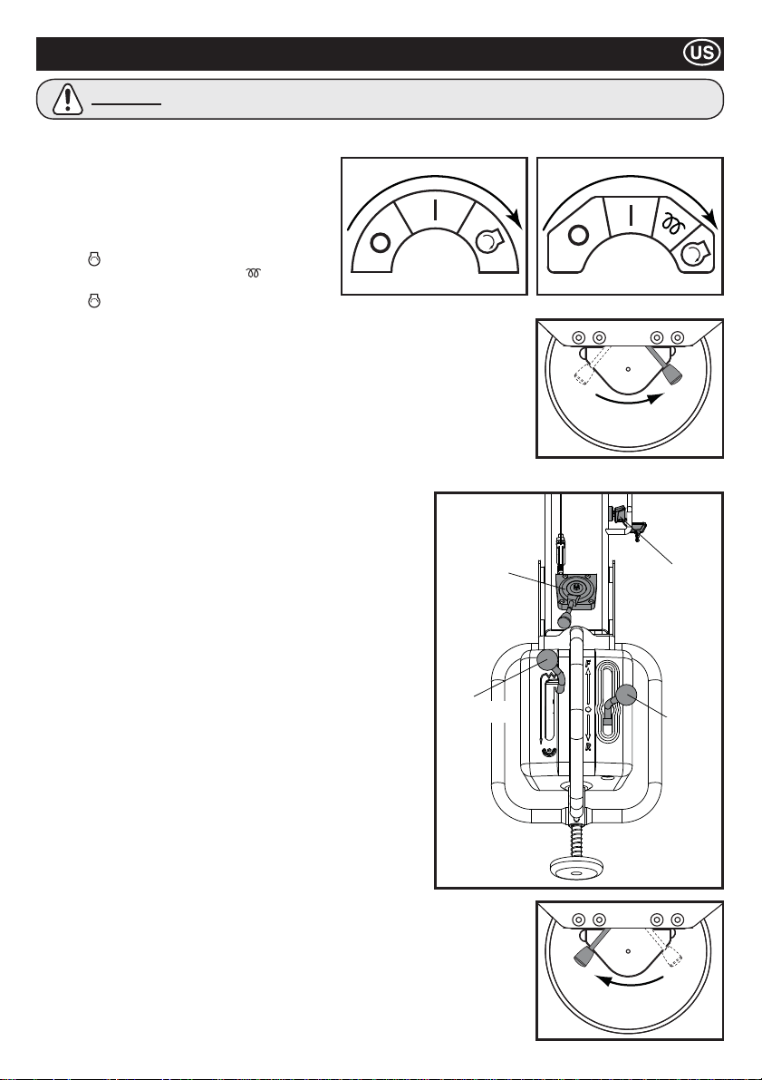
Start / Stop Procedure
CAUTION
Before starting the engine, make sure that the Drive Lever is at Neutral, Vibration Lever is at OFF, and the Parking Lever is at ON
position.
1. Open the fuel tap at the engine.
2. Move the Throttle Lever on the Operation Handle to
the Full Throttle (Hare) position.
Start the Engine – Electric Start
3ai. YANMAR Start
3aii. KUBOTA - From cool, hold on Heat position for 10
secs.
Start
DO NOT crank for an extended period. Maximum 10 secs.
3b. After the engine has been started, make sure that the key is set to ON (I) position during
the operation. (Setting the Key Switch to OFF (0) position would not allow the generator to
charge the battery.)
Start the Engine – Manual Start
4a. Grasp the recoil starter handle.
4b. Pull the handle out slowly until you fee lstrong resistance.
4c. Slowly return the recoil starter to the initial position.
4d. Push the decompression lever down and then release it. The decompression lever will
automatically return to the original position when the engine starts.
4e. Grasp the recoil starter handle.
4f. Pull the handle all the way out with a strong and even motion. Use two hands if necessary.
4g. Slowly return the starter handle to the initial position.
4h. If the engine does not start, repeat the procedure from step 4b.
5. Move the Throttle Lever to LOW position, and let the engine run at idle
for a few minutes to warm up.
6. After the engine has warmed up, the machine is ready for operation.
7. Move the throttle lever to the high speed “H” position quickly to prevent
damage from occurring to the clutch. The “Full Throttle” position of this
machine has been preset at the factory to achieve optimum machine
performance.
DO NOT alter this setting since premature wear or tear can result, and
both engine and machine warranty will be automatically voided.
8. Move the Parking Brake Lever to the right to disengage it.
NOTE: Negligence to disengage the Parking Brake before attempting to
drive the machine forward or reverse will result in the severe
damage to the parking brake mechanism as well as the drive system.
9. Operators Control
9a. Throttle Lever
Always keep the Throttle Lever at High position during the operation.
DO NOT attempt to alter the travel speed by changing the engine
revolution.
9b. Drive Lever
Move the Drive Lever forward to drive the machine forward.
For reverse motion, move the lever backward.
9c. Vibration Lever
By shifting the Vibration Lever to ON position, the vibration mechanism
will be engaged, and produce the vibration.
10. Stopping the Engine
11. In preparation for stopping the engine, move the throttle lever
to LOW position.
12. Allow the engine to idle for 1-3 minutes.
13. Move the Throttle Lever to STOP position to stop the engine.
Then, set the Key Switch to “OFF” position. The buzzer will sound
when the Key Switch is set to ON while the engine is stopped.
14. Close the Fuel tap
15. Apply parking brake by swinging the Parking Brake Lever to the left.
position, and hold it until the engine starts.
Turn the Key Switch at the Throttle Lever to
position, and hold it until the engine starts.
DO NOT let your hands off from the Starting Handle during the Starting procedures.
YANMAR KUBOTA
Turn the Key Switch at the Throttle Lever to
THROTTLE
LEVER
VIBRATION
LEVER
DISENGAGE
ENGAGE
KEY
SWITCH
DRIVE
LEVER
25
Page 26

Operating the TDX 650A Roller
Ɣ Having carried out the checks listed in the ‘pre start’ section, you may start the engine.
The ALTRAD Belle TDX 650A Roller is ¿ tted with a centrifugal clutch; this allows the engine to run at idle without driving the
Hydraulic pump.
Ɣ As the engine speed is increased the clutch will engage and the engine will drive the Hydraulic Pump to send the hydraulic
power to drive the drums, and to drive the vibration mechanism as well. To avoid any damage to the centrifugal clutch, move
the throttle lever quickly from L to H position. For correct operation, the engine speed should be set to maximum during the
compaction operation
Ɣ Avoid operating the machine on a fully compacted, hard, or non-yielding surface. Otherwise, the bearings and other mechanical
components will be damaged, and the life of the machine will be greatly reduced.
Ɣ When working on a steep slope, pay extra care in operating the machine so that the machine roll down the slope.
Always work up or down the slop. Do not work across the slope. If the machine is parked on a slope, always apply the Parking
Brake Lever.
Ɣ When the machine is going in reverse, make sure not to stand behind the Operation Handle. Always walk along the Operation
Handle and face toward the direction of travel.
Ɣ Lifting
Where it is necessary to use lifting equipment to position the TDX 650A, make sure the lifting equipment has a WLL (Working Load
Limit) suitable for the machine’s weight (see T ecnical Data table). Attach suitable chains or slings ONL Y to the lifting points provided
at the centre of the machine (Lifting Eye) or at each corner of the machine (Strapping Points).
Ɣ TRANSPORTATION
Transportation on a vehicle.
Make sure to lock the Handle and use proper slopes of suf¿ cient width, length, and strength on loading to and unloading from
the vehicle.
Ɣ Apply the parking brake, and tie the machine ¿ rmly to the vehicle during the transportation.
Servicing
Maintenance
The ALTRAD Belle TDX 650A is designed to give many years of trouble free operation. It is, however, important that the simple
regular maintenance listed in this section is carried out. It is recommended that an approved ALTRAD Belle dealer carries out all major
maintenance and repairs. Always use genuine ALTRAD Belle replacement parts, the use of spurious parts may void your warranty.
Before any maintenance is carried out on the machine, switch off the engine and remove Key from the Key Switch
Always set the machine on level ground to ensure any À uid levels will be correctly read. Only use recommended oils (see page 28).
Servicing the Engine
Service the engine according to the engine manufacturer’s speci¿ cations.
Refer to the engine operation and maintenance manual.
Note: When the Maintenance Cover has been removed, ensure that all Bolts are securely fastened when re-¿ tting. DO NOT restart the
machine with guards removed.
Maintenance: Every 8 hours or daily
1. Check for loose bolts and nuts, retighten if necessary.
2. Check and clean the air ¿ lter element, re-lube the element in accordance with the engine manufacturer’s recommendations. If
operating conditions are unusually dusty and severe, ¿ lter element cleaning should be done more frequently.
3. Check Engine Oil Level before operation.
Maintenance: After ¿ rst 50 hours and every 200 hours thereafter
1. Change the Engine Oil - see procedure on page 28.
26
Page 27
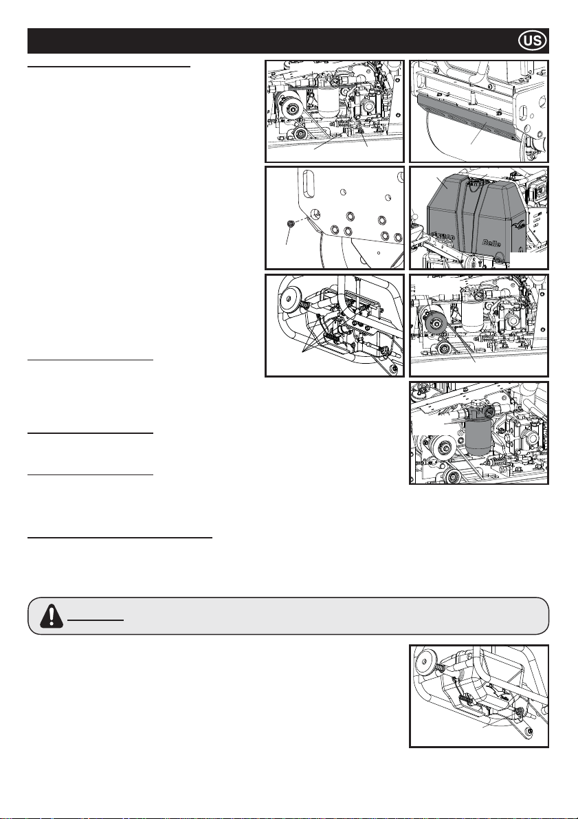
Servicing
Maintenance: Every 50 hours or weekly
1. Check for the tension of Drive Belt
1a. Loosen four bolts, which ¿ xes the Pump Bracket, and
turn the Adjust Bolt until proper tension is achieved.
The belt should deÀ ect by 5mm at the center between
Centrifugal clutch and pump pulley.
1b. Tighten four bolts at the Pump Bracket. When the belt
is worn out or cracked, renew the belt.
2. Adjust the clearance of Scraper
2a. Remove the Scraper, and wipe of all the dirt, mud, and
asphalt.
2b. Re¿ t the Scraper to the Scraper Bracket and ¿ x it with
suitable clearance (1mm) from the drum.
3. Water Tank
3a. Drain all the water, and clean the inside of the tank
using a hose
4. Sprinkler Nozzle
4a. Remove the Cap from the nozzle, and clean the inside
of Sprinkler Nozzle.
5. Moving Parts
Feed grease to the Rod End of the Drive/Vibration Cable.
5a.
5b.
Re-Grease the Greasing Points in the Operation Handle.
5c. Grease the Vibrator Shaft
Maintenance: Every 100 hours
1. Vibration Clutch Mechanism
1a. Check to con¿ rm that the Vibration Clutch Mechanism
works properly.
1b. Feed grease to the moving part.
1c. Check the condition of V-belt. When it is worn out or cracked, renew the belt.
Maintenance: Every 500 hours
1. Replace the Hydraulic Oil Filter Element at every 500 hours of operation.
Use Genuine Filter element.
Maintenance: Every 800 hours
1. Replace the Hydraulic Oil. Flush off the tank before supplying the new Hydraulic Oil.
To vent the air in the hydraulic system, leave the Tank Cover open, and run the engine at
its maximum speed without operating the Drive Lever and Vibration Lever for 10 minutes.
Then, re¿ t the Tank Cover.
Adjusting The Neutral Setting Of Drive Lever
The neutral position of the Drive Lever may be shifted due to the vibration or wear of the drive cables. To adjust the Neutral Setting,
follow the instructions below;
1. Place the machine on a level surface.
2. Make sure that the engine is turned off.
3. Remove the Nut which ¿ x the Rod End of Drive Cable to the Drive Lever.
Do not attempt to start the engine when this nut is off its position. Machine may move suddenly and
WARNING
4. Loosen the Lock Nut at the Rod End.
5. Turn the Rod End either clockwise or counterclockwise depending upon the direction of
shifted neutral position.
6. Re¿ t the Rod End to the Drive Wire, and secure it with nut.
7. Start the engine, and increase the engine revolution to maximum. Observe to see if the
neutral position has been properly adjusted.
8. If not, stop the engine, remove the nut, and repeat the procedure 5 to 7 until the neutral
position is properly set.
9. When the neutral position is correctly adjusted, apply Loctite to the Nut, which ¿ x the Rod
End, and tighten it. Then, tighten the Lock Nut at the rod end.
irrationally without the capability of being controlled with the Drive Lever, which may cause severe injury or
property damage.
DRIVE BELT
BELT ADJUSTER
SPRINKLER
CAP
GREASING
POINTS
BRACKET BOLT
SCRAPER
TANK
VIBRATION
CLUTCH
FILTER
ELEMENT
LOCK NUT
V-BELT
CAP
DRAIN
PLUG
27
Page 28
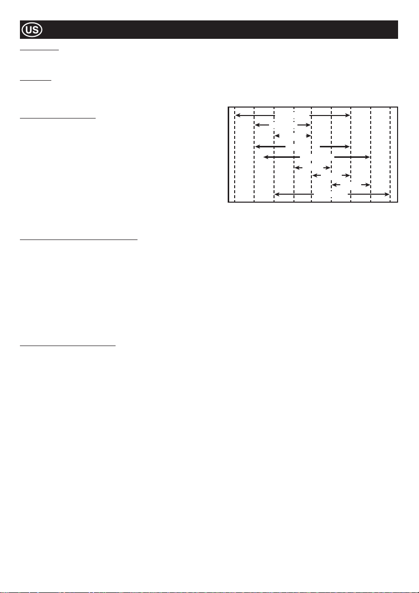
Servicing
Hydraulic Oil
Ɣ Total EP32, Shell Tellus T37, MOBIL DTE15 or ESSO Unipower, XL46.
Engine Oil
Select the appropriate engine oil viscosity based on the ambient temperature and use the SAE Service Grade Viscosity Chart below.
This machine is ¿ lled with SAE 15W-40 at the factory.
-4°F
SAE 10W
14°F
(-10°C)
SAE 5W-30
SAE 20W
SAE 10W-30
32°F
(0°C)
SAE 15W-40
SAE 20
SAE 30
SAE 20W-50
50°F
68°F
(10°C)
(20°C)
SAE 40
86°F
(30°C)
104°F
(40°C)
122°F
(50°C)
Engine Oil Speci¿ cations
Use an engine oil that meets or exceeds the following guidelines
and classi¿ cations:
Service Categories
Ɣ API Service Categories CD or higher.
Ɣ ACEA Service Categories E-3, E-4 and E-5
Ɣ JASO Service Category DH-1
De¿ nitions
Ɣ API Classi¿ cation (American Petroleum Institute)
Ɣ ACEA Classi¿ cation (Association des Constructeurs Européens
d’automobilies)
Ɣ JASO (Japanese Automobile Standards Organisation)
30°F
(22°C)
(-20°C)
Engine Oil Change Procedure - Yanmar
1. Ensure the Roller is on a level surface and the operating handle in the storage position. Apply the Park Brake.
2. Loosen the nut on the underside of the oil ¿ ll / drain plug. NOTE:- DO NOT remove the plug at this stage.
3. Slide the hose from the side panel.
4. Remove 4 x M8 Set Screws using a 13mm spanner. Remove side panel.
5. Bring the hose out of the chassis, remove the plug and drain the oil into a container.
6. Re-¿ t the side panel using a 13mm spanner and slide the oil ¿ ll / drain hose back into the slot in the panel. Tighten the nut to secure
to the side panel but leave the plug removed.
7. Using a funnel, pour oil into the ¿ ller hose. Care must be taken whilst ¿ lling to ensure capacity is not exceeded. Use a dipstick on
left-hand side of the engine to check oil level.
8. Re-¿ t oil ¿ ll / drain plug.
9. Check that the machine functions correctly.
Battery Replacement Procedure
1. Remove the 4 x Bolts from the side guard using a 13mm Socket and remove the side guard. Save the fasteners.
2. Using an 11mm spanner, remove the earth cable from the battery then remove the positive cable from the battery.
3. Remove the battery clamp and pad. Remove 2 x nuts and 2 x washers using a 13mm spanner.
4. Remove the long battery stud and washer using a 13mm spanner.
5. Remove 2 x bolts from the regulator using 10mm socket.
6. Remove bracket which was behind the regulator using a 10mm socket. Ensure not to lose the spacer from behind the bracket.
7. Move the À exible cable retaining strap and pull the wires out.
8. Slide the battery out and replace with the new battery.
9. Put the wires into back into place and secure in place with the cable retaining strap.
10. Re-¿ t bracket and spacer and tighten to 12Nm.
11. Re-¿ t the 2 x bolts into the regulator and tighten to 12Nm.
12. Re-¿ t the battery stud and washer and tighten to 28Nm.
13. Re-¿ t the battery clamp and pad using 13mm spanner. Tighten the nut to ensure that 8mm of thread is exposed.
14. Attach the positive cable to the battery followed by the earth cable.
15. Re-¿ t the side guard. Tighten the 4 x bolts to 28Nm.
28
Page 29
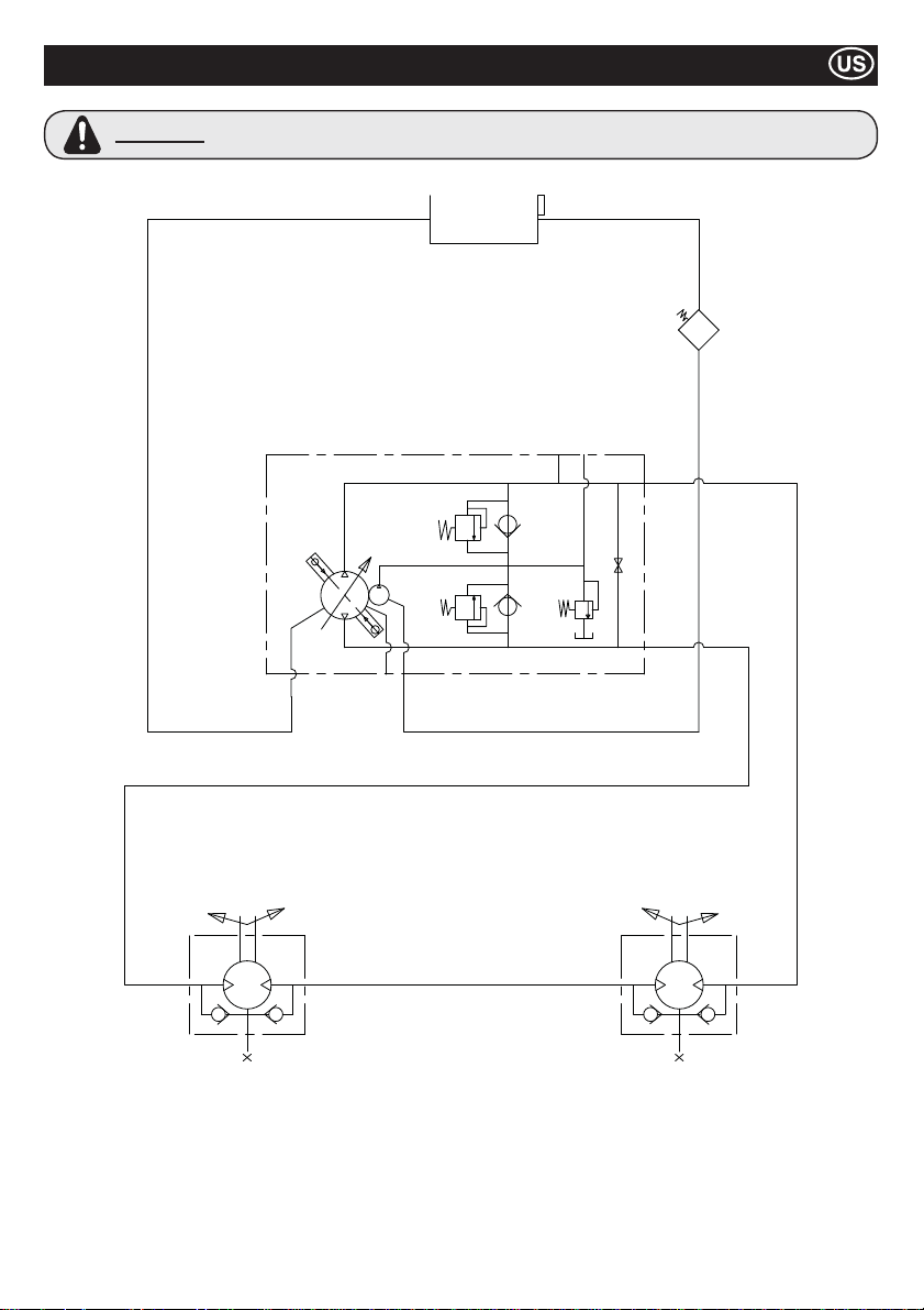
Hydraulic Circuit
WARNING
If carrying out any repairs on the Hydraulic Circuit the tank ¿ ller cap must be loosened to ensure the
system is not pressurised.
29
Page 30
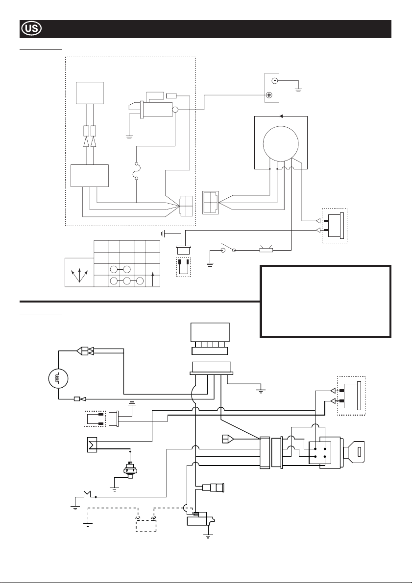
Yanmar L100N
Wiring Diagram
Kubota EA330
12V - 15A
Dynamo
G/W G/W
CB104 CB104
CA104 CA104
G/W G/W
Regulator
HOW KEY SWITCH FUNCTION
OFF
OFF12
1
2
Y
Starter Motor
DC12v 0.8kW
W
JAS0
D601
20T
W
G
IG BAT ST NOTE
AUTO
AV2 0
Switch
AV1.25
AV1.25
AV1.25
AV2 0
M8
Screw
R
RY
B
B
Link Wire
BR
G
W
YAZAKI NO.
7322-2446
R
WG
Oil Pressure
Ground
YAZAKI NO.
7323-2446
Y
Hour Clock
Ground
Battery
Diode
Key Switch
BAT
(15)
ST
IG
(75)
(50)
(30)
Y
G
R
W
Y
Siren
Hour Clock
Option
Inventory
G = Green IG = Ignition
W = White BAT = Battery
Y = Yellow ST = Start
R = Red BK = Black
Regulator
BL = Blue SB = Sky Blue
OR = Orange BR = Brown
Y
SBGBK
SB
R
Fan
Dynamo
Hour Clock
Link Wire
R
B
Buzzer
Oil Switch
Glow Plug
BK/R
SB
BK
Y
Battery
BR
R
Y
BR
BR
Y
Y
Y
W
BK/R
R
BK/W
W
Y
G
R
Hour Clock
Option
Starter Switch
R
Fuse
Starter
30
Page 31
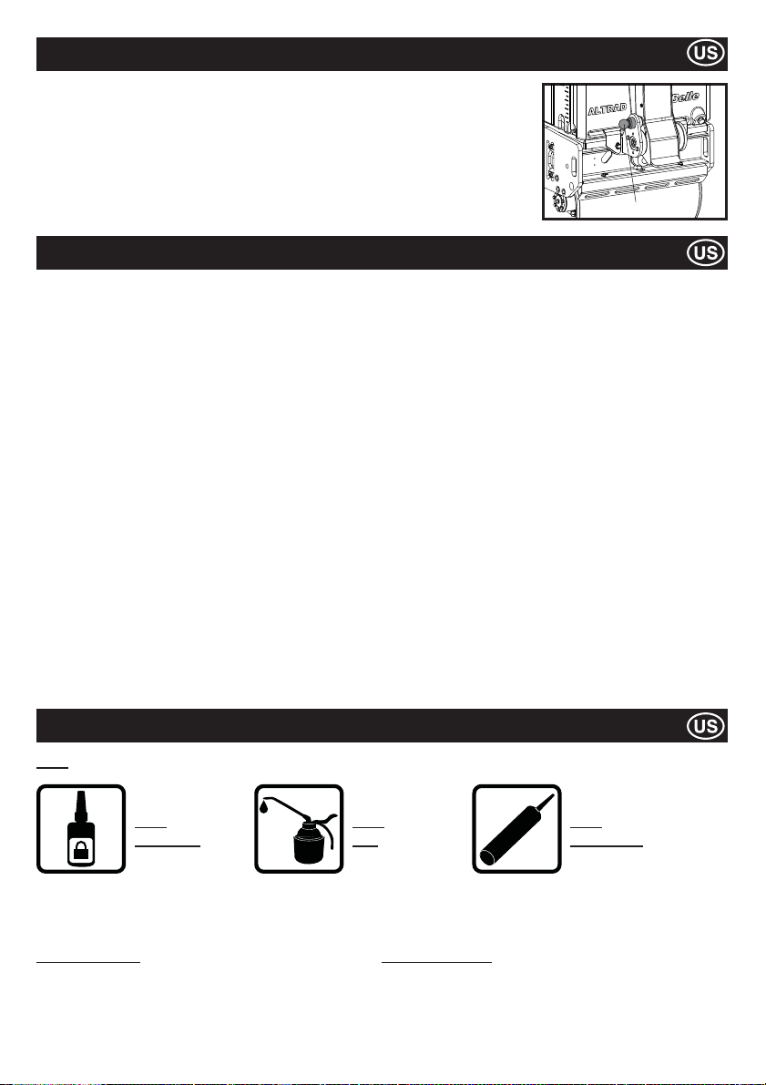
Long Term Storage
1. For long-term storage, empty the fuel from the Fuel Tank by either sucking the remaining fuel
out from the Fuel Inlet port or from the Fuel Filter after the ¿ lter cup has been removed.
2. Clean the Air Cleaner Element.
3. Clean-up the oil and dust accumulation on all rubber parts.
4. Clean the base plate and apply a light coating of oil to prevent rust formation.
5. Cover the machine and store it in a dry place.
6. The Operation Handle can be stood up for storage. Pull the Stopper, and raise the handle.
Make sure that the Stopper securely holds the Operation Handle.
LATCH
Warranty
Your new ALTRAD Belle TDX 650A Roller is warranted to the original purchaser for a period of one-year (12 months) from the original
date of purchase.
The Altrad Belle warranty is against defects in design, materials an workmanship.
The following are not covered under the Altrad Belle warranty:
1. Damage caused by abuse, misuse, dropping or other similar damage caused by or as a result of failure to follow assembly,
operation or user maintenance instructions.
2. Alterations, additions or repairs carried out by persons other than Altrad Belle or their recognised agents.
3. Transportation or shipment costs to and from Altrad Belle or their recognised agents, for repair or assessment against a
warranty claim, on any machine.
4. Materials and/or labour costs to renew, repair or replace components due to fair wear and tear.
The following components are not covered by warranty.
· Engine air ¿ lter
Altrad Belle and/or their recognised agents, directors, employees or insurers will not be held liable for consequential or other damages,
losses or expenses in connection with or by reason of or the inability to use the machine for any purpose.
Warranty Claims
All warranty claims should ¿ rstly be directed to Altrad Belle, either by telephone, by Fax, by Email, or in writing.
For warranty claims:
Altrad Belle Inc
PO Box 13225, Roanoke,
VA, 24032,
USA
Spare Parts Information
KEY
USE
LOCTITE
For information regarding Spare Parts availability please contact the ALTRAD Belle Inc. using the following contact details:Altrad Belle Inc, PO Box 13225, Roanoke, VA, 24032, USA
# - Colour Option 1 ## - Colour Option 2
Part No. + S = Orange (Eg. 981/05100S) Part No. + GR = Grey (Eg. 981/03200GR)
Part No. + G = Green Part No. + GR2 = Quartz Grey
Part No. + B1 = Blue Part No. + BL = Black
Part No. + R1 = Red Part No. + W = White
Part No. + Y = Yellow
Part No. + Y2 = Yellow
USE
OIL
31
ILICONE
S
USE
SILICONE
Page 32
Comment Utiliser Ce Manuel
Ce manuel a été rédigé a¿ n de vous aider à opérer en toute securité et effectuer la maintenance du Rouleau Compresseur Vibratoire à
Conduite Manuelle, Altrad Belle. Ce manuel est prévu pour les revendeurs et opérateurs des modèles TDX 650A.
Avant-propos
La section “Environnement” donne des instructions sur la manière de recycler l’appareil abandonné dans le respect de
l’environnement.
La section “Description de la machine” vous aide a vous familiariser avec la structure et les commandes de la machine.
Les sections “Sécurité Générale” et “Santé et Sécurité” présente le mode d’emploi de la machine a¿ n d’assurer votre sécurité et la
sécurité du public.
La “Procedure de Démarrage et d’Arrêt” vous aide à démarrer et à arrêter la machine.
Le guide “Trouble Shooting” vous aide si vous avez un problème avec votre machine.
La section “Contrôle” vous aide avec la maintenance générale et le contôle technique de votre machine
La section “Liste et Schéma des Pièces” vous explique les détails des composantes de votre machine et les numéros des pièces qui
s’appliquent si le besoin de les remplacer se presente.
Directives relatives à la notation
Dans ce manuel, les textes auquels il faut accorder une attention particulière sont illustrés de la façon suivante.
ATTENTION
Ce produit présente des risques. La machine ou vous-même peut subir des dommages si les
procédures ne sont pas effectuées de la façon prévue.
AVERTISSEMENT
Il peut exister des risques pour la vie de l’opérateur.
AVERTISSMENT
AVERTISSEMENT
SACHEZ comment utiliser les commandes de l’appareil et ce qu’on doit faire pour assurer la maintenance en toute securité.
(Note : Soyez sûr de la façon d’arrêter la machine avant de la mettre en marche, au cas où vous vous retrouverez en dif¿ culté.
Portez TOUJOURS les équipements de sécurité qui sont prévus pour votre protection personnelle. Si vous avez DES QUESTIONS sur
l’usage securisé ou sur la maintenance de cette appareil DEMANDEZ À VOTRE SUPERVISEUR OU PRENEZ CONTACT AVEC AVEC
LES ENTREPRISES ALTRAD BELLE SUIVANTES. ALTRAD BELLE (England, Tel: +44(0)1298 84606)
Avant de faire fontionner ou d’effectuer de la maintenance sur cette machine, VOUS DEVEZ
LIRE et ETUDIER ce manuel.
Sommaire
Comment utiliser ce manuel .....................................................................................................................................................................32
Avertissement ...........................................................................................................................................................................................32
Données Techniques ................................................................................................................................................................................33
Etiquettes..........................................................................................................................................................................................34 - 35
Description de la machine ........................................................................................................................................................................36
Le Sécurité en Générale ..........................................................................................................................................................................36
La Santé et la sécurité .............................................................................................................................................................................37
Véri¿ cation Avant Démarrage (Pré-Démarrage) ......................................................................................................................................37
Environnement .........................................................................................................................................................................................37
Procédure de mise en marche/d’arrêt ......................................................................................................................................................38
Le fonctionnement des Rouleaux TDX ....................................................................................................................................................39
Les Contrôles ................................................................................................................................................................................... 39 - 41
Circuit hydraulique ....................................................................................................................................................................................42
Schéma de câblage..................................................................................................................................................................................43
Le Stockage à long terme ........................................................................................................................................................................44
Garantie ....................................................................................................................................................................................................44
Informations Pièces Détachées................................................................................................................................................................44
Declaration de Conformité..........................................................................................................................................................................2
Altrad Belle a adopté une politique de développement permanent de ses produits et se réserve le droit de modi¿ er les manuels sans préavis
32
Page 33
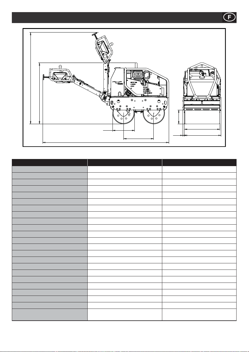
B
D
C
A
H
G
E
F
J
Données Techniques
Model TDX 650A Yanmar L100N TDX 650A Kubota EA330
Poids* - Kg 675 684
A - Longueur Globale - mm 2318 2318
B - Hauteur Globale - mm 1137 1137
C - Socle de roue - mm 560 560
D - Diamètre du Tambour - mm 402 402
E - Largeur du Tambour - mm 650 650
F - Largeur Globale - mm 703 703
G - Distance de Bordure - mm 258 258
H - Surplomb Latéral - mm 26.5 26.5
J - Hauteur Entreposage - mm 1678 1678
Vitesse marche avant - m/m (km/h) 0 - 70 (0 - 4.2) 0 - 70 (0 - 4.2)
Vitesse marche arrière - m/m (km/h) 0 - 38 (0 - 2.3) 0 - 38 (0 - 2.3)
Fréquence de vibration - v.p.m 3300 3300
Force centrifuge - kN 16 16
Capacité du Réservoir d’eau - Ltr 65 65
Capacité du Réservoir Hydraulique d’huile - Ltr
Engine YANMAR L100N KUBOTA EA330
Type 4 Temps refroidi a l’air 4 temps refroidi à l’eau
Carburant Diesel Diesel
Réservoir d’essence - Ltr 5.4 4.8
Taux de rendement - Hp (kW) 9 (6.6) 5.9 (4.4)
Puissance Maximum de Sortie - Hp (kW) 10 (7.4) 6.9 (5.2)
Démarrage
* Le poids est sans eau dans le réservoir d’eau. Eau dans le réservoir = 65litres = 65 kg.
Démarrage Electrique (avec l’option d’un
16 16
lanceur à rappel)
33
Électrique
Page 34
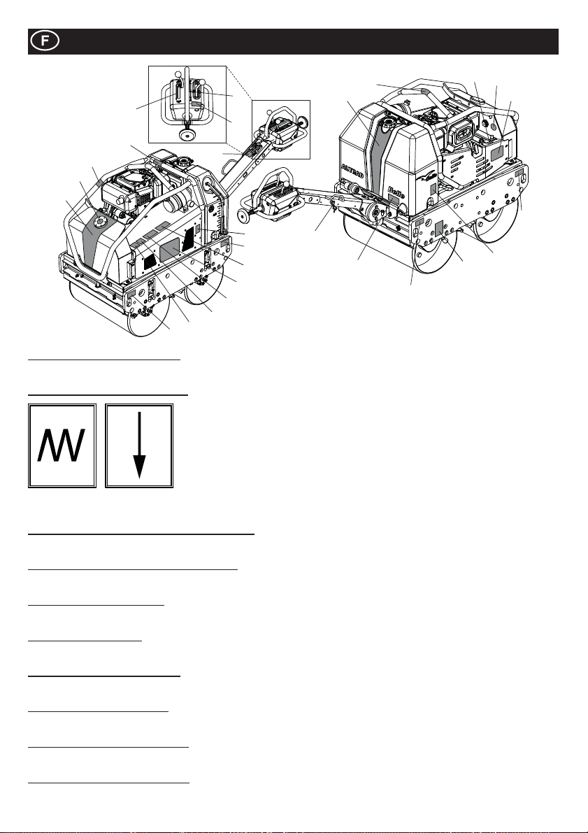
5
17
10
18
1
9
Postes 1 to 4 - Etiquettes de Marque
Etiquettes pour identi¿ er le rouleau TDX.
Poste 5 - Etiquettes Poignée Vibration
Etiquettes
13
7
6
21
8
9
25
3
24
23
22
Note:- Les images montrent le modèle Yanmar L100N
20
19
2
14
9
12
4
9
16
15
Vibration
Sélectionnée
Poste 6 - Etiquette: Attention - lire manual d’opération
ATTENTION! Merci de lire le manuel d’opération, avant utiliser cette machine.
Poste 7 - Etiquette: Poignée, marche avant/arrière
Poignée de direction. F = Avant, R = Arrière, Ɣ = Neutre.
Poste 8 - Etiquette: Maintenance
Indique que le couvercle est enlevé pour faire les maintenances périodiques.
Poste 9 - Etiquette: ¿ xation
Indique les points de ¿ xation pour levage ou pour le transport.
Poste 10 - Etiquette: surface chaude
ATTENTION! Surfaces chaude autour du réservoir hydraulique et pot d’échappement.
Poste 11 - Etiquette: huile moteur
Indique où remplir et véri¿ er le niveau d’huile moteur
Poste 12 - Etiquette: huile hydraulique
Indique le gauge huile hydraulique, ce qui montre le niveau d’huile hydraulique dans le réservoir.
Poste 13 - Etiquette: type huile moteur
Signi¿ e quel type huile à utiliser dans ce moteur.
Vibration
Dégagée
34
Page 35
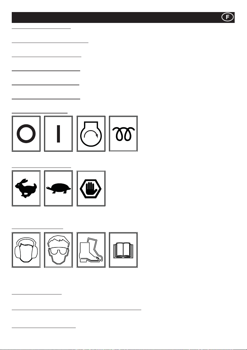
Etiquettes
Poste 14 - Etiquette: Vidange-eau
Si la température ambiente est anticipée inférieure a zéro, le réservoir doit être vidé par ce bouchon.
Poste 15 - Etiquette: frein de stationnement
Montre le frein de stationnement. A appliquer lorsque la machine n’est pas en fonction.
Poste 16 - Etiquette: robinet d’arrosage
Montre les robinets d’arrosage, et quel robinet s’applique pour la barre d’arrosage.
Poste 17 - Etiquette: Gazole seulement
Pour le moteur utiliser seulement la gazole.
Poste 18 - Etiquette: huile hydraulique
Positionnement du bouchon pour le réservoir huile hydraulique.
Poste 19 - Etiquette: crochet de levage
Poignée sur le dessus de la machine a utiliser avec chariot / crochet élévateur
Poste 20 - Etiquette: de ignition
Fermée Ouvret Démarrer
Poste 21 - Etiquette: Accelérateur
Position tr/
min Max.
Position
Ralenti
Position
arrêt
Chaleur
(KUBOTA)
d’urgence
Poste 22 - Etiquette: Sécurité
Port De
Protection
Acoustique
Poste 23 - Etiquette du Bruit
Puissance sonore de la machine (en décibels)
Poste 24 - Autocollant d’avertissement relatif aux fumées d’échappement
Les moteurs émettent du monoxyde de carbone; Utiliser seulement en zone bien ventilée.
Poste 25 - Autocollant d’écrasement
ATTENTION! Mé¿ ez-vous des composants mécaniques si le protecteur est retiré.
Port De
Lunettes De
Protection
Port De
Chaussures
De
Protection
Lire Le
Manuel
D’utilisation
35
Page 36
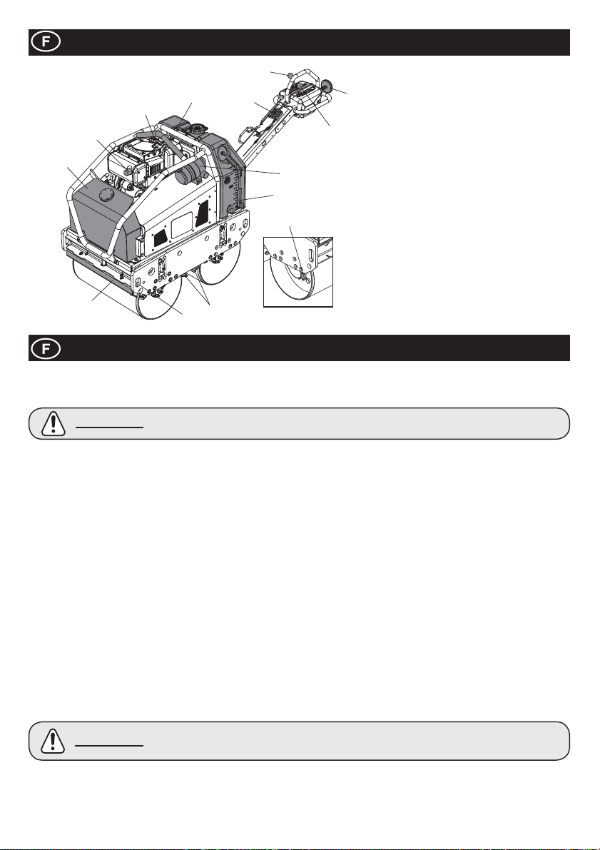
Description de la machine
5
1. Réservoir d’huile hydraulique.
2
12
1
10
4
11
8
3
9
13
10
7
2. Point du Levage.
6
3. Filtre à air.
4. Réservoir d’eau.
5. Levier de marche avant/arrière.
6. Levier de Vibration.
7. Sécurité marche arrière.
8. Levier d’accélérateur.
9. Jauge de niveau d’eau.
10. Racleurs.
11. Anneaux d’amarrage.
12. Echappement.
13. Frein à main
Note:- Les images montrent le modèle
Yanmar L100N
Securité en Général
Pour votre propre protection personnelle et pour la securité des personnes autour de vous, veuillez lire et assurer que vous comprenez
totalement les informations suivantes sur la sécurité. C’est la responsabilité de l’opérateur d’assurer que Il ou ELLE comprend
totalement comment faire marcher cet équipement dans les conditions de securité. Si vous n’êtes pas sûr de l’usage approprié et
sécurisé de votre TDX 650A, veuillez consulter votre superviseur ou Altrad Belle.
ATTENTION
Ɣ Cette machine doit servir uniquement à utilisation à laquelle elle est destinée.
Ɣ
C’est uniquement du personnel bien formé qui doit opérer cette machine.
Ɣ
Le propriétaire de la machine doit respecter, et former l’opérateur de la machine à respecter la Réglementation en matière de
Protection des Travailleurs, en vigueur dans le pays d’utilisation.
Ɣ
Utliser un équipement de soulevement adéquate pour soulever la machine.
Ɣ
Cette machine doit fonctionner au niveau du sol où la stabilité est garantie. Lorsque l’on travaille près du bord de tranchés le
creusées, utilisez la machine correctement a¿ n d’éviter qu’elle s’écroule ou tombe.
Ɣ
Si la surfacer à compacter se trouve sur une pente, un grand soin doit être employé dans le contrôle du sens de marche de la
machine. Travaillez toujours en amont et en aval de la pente, pas à travers. Si la machine est à l’arrêt sur une pente, toujours
appliquer le frein de stationnement.
Etablissez un cordon de démarcation du perimètre de travail et gardez le public et le personnel non-autorisé à une distance sûre.
Ɣ
Ɣ
Assurez-vous que vous savez comment ÉTEINDRE cette machine avant de L’ALLUMER au cas ou vous rencontrerez des dif¿ cultés.
Ɣ Eteignez toujour le moteur avant le contrôle.
Ɣ
Pendant l’utilisation le moteur devient très chaud, laissez refroidir le moteur avant de le toucher.
Ne laissez jamais le moteur en marche sans surveillance.
Ɣ
Ɣ
Ne jamais enlever ou altérer les dispositifs de sureté installés, ils sont là pour votre protection. Toujours véri¿ er la condition et la
sureté des dispoitifs. Si’il y en a qui sont abîmés ou qui manquent, NE PAS UTILISER LA MACHINE avant que le dispositif de
securité a été remplacé ou réparé.
Ne pas faire functionner la machine si vous êtes malade, fatigué, ou sous l’inÀ uence d’acool ou de drogues.
Ɣ
Ɣ
Cette machine a été conçue pour éliminer les risques qui peuvent survenir au cours de son utilisation. Cependant, il RESTE
TOUJOURS des risques, et ces risques résiduels ne sont pas clairement reconnaissables, et peuvent abîmer les biens
materiels, ou occasioner des blessures aux personnes et causer même la mort. Si de tel risques imprévisibles et imperceptibles
deviennent évidents, la machine doit être arrêtée immédiatement, et l’opérateur et son superviseur doivent prendre les mesures
adéquates a¿ n d’éliminer ces risques. Il est parfois nécessaire d’informer le fabriquant d’un tel incident pour qu’à l’avenir il puisse
contre-balancer les données.
Surêté du carburant
ATTENTION
Ɣ
Avant de remettre du carburant, éteignez le moteur et laissez-le refroidir.
Pendant le remplissage du carburant, NE PAS fumer ou laisser des À ammes nues dans le perimètre.
Ɣ
Ɣ
Pendant le remplissage du carburant, utilisez un entonnoir adéquat, et évitez le déversement par-dessus le moteur.
Ɣ
Le carburant déversé doit être rendu inoffensif avec du sable immédiatement. Si du carburant a été versé sur vos vêtements, changez-les.
Ɣ Stocker le carburant dans un récipient homologué à cette effet, et loin de toute source inÀ ammable.
Une maintenance insuf¿ sante peut s’avérer risquée.
Veuillez lire a¿ n de comprendre cette section avant d’effectuer toute maintenance, contrôle réparation.
Le carburant est inÀ ammable. Il peut inÀ iger des blessures et des dommages au bien d’autrui. Fermer
le moteur, éteindre toute À amme ouverte et ne pas fumer pendant le remplissage du réservoir. Toujours
essuyer le carburant qui a été déversé.
36
Page 37
La Santé et la sécurité
Les Vibrations
Des vibrations emanant du fonctionnement des machines sont transmis via la manche jusqu’aux mains de l’opérateur. Le Rouleau
Compresseur Vibrant à Conduite Manuelle, Altrad Belle de la TDX-Series a été conçu pour réduire le niveau de vibration Main/
Bras. Consulter les spéci¿ cations et les données techniques pour les niveaux de vibration et le temps (temps maximum d’exposition
jounalière conseillé). Ne dépassez pas le temps d’utilisation maximum.
EPP (L’Equipement Personnel de Protection)
L’EPP approprié doit être porté lors de l’utilisation de cette appareil, c’est-à-dire Lunettes Protectrices, Gants, Protection Auditive,
Masque Anti-poussière et des Chaussures renforcées devant avec de l’acier. Portez des vêtements qui conviennent au travail que vous
faites. Nouez les cheveux long et enlevez tout bijou, qui peut se coincer dans les parties mobile de l’appareil.
La Poussière
Le processus de compactage peut produire de la poussière, ce qui peut présenter un risque pour votre santé. Portez toujours un
masque adéquat pour le genre de poussière qui est produite.
Le Carburant
N’ingérez pas et n’ inspirez pas les vapeurs émies par le carbuant. Lavez tout eclaboussure de carburant immédiatement. En cas de
contact avec les yeux, lavez abondamment avec de l’eau et consultez votre medécin le plus tôt possible.
Les Gaz d’échappement
Ne pas faire marcher la machine à l’intérieur or dans un lieu con¿ né, assurer que la zone de travail est suf¿ sament ventilée.
AVERTISSEMENT
Les fumées émises par cet équipement sont hautement toxiques et peuvent tuer.
Véri¿ cations avant le démarrage
Inspections Pré-démarrage
Les inspections pré-démarrage doivent s’effectuer avant le démarrage de chaque session de travail ou après tous les quatre heures
d’usage, selon ce qui arrive en premier. Veuillez consulter la section des contrôles pour des instructions détaillées. Si un défaut est
constaté, la machine ne doit pas servir avant la récti¿ cation du défaut.
1. Inspectez complètement la machine pour des signes de détériorations
2. Véri¿ ez les tuyaux, des ouvertures de remplissage, égouttez les prises et toute autre point pour des signes de fuite.
Réparez les fuites avant de commencer
3. Véri¿ ez le niveau d’huile et remplissez à niveau si necessaire.
3a. Placez la machine sur une surface plate, et véri¿ ez le niveau d’huile du moteur.
3b. Enlevez le dispositif de emplissage d’huile, et constatez si l’huile arrive jusqu’au bord de l’ouverture de la remplisseuse.
Utilisez de l’huile de moteur adéquat avec la bonne visosité. (Se il vous plaît voir le graphique de grade de viscosité SAE dans la
section de l’entretien)
4. Véri¿ ez le niveau de carburant du moteur et en rajoutez si necessaire. Utilisez du carburant propre. L’utilisation de carburant
contaminé peut endommager le réseau pour le carburant
5. Véri¿ ez que le ¿ ltre d’air est propre. L’accumulation excessive de terre/poussière dans l’élément de ¿ ltrage provoquera un
fonctionnement erratique du moteur. Nettoyez l’élément de ¿ ltrage quand il est contaminé. (Voir section sur la maintenance.)
6. Véri¿ ez les fonctions des Commandes de L’Opérateur. Assurez-vous que le Levier de Conduite, Levier de Vibrations, Levier de la
Soupape, le Levier de Stationnement et le Dispositif de Securité pour la marche arrière sont actionnés sans accros.
7. Veri¿ er le niveau de liquide de refroidissement. Remplir jusqu’au niveau si necessaire - KUBOTA SEULEMENT.
Environnement
Destruction Securisé
Les instructions pour la protection de l’environnement.
La machine contient des matières de valeur.
Portez l’appareil et les accessoires à jeter au services
de recyclage appropriés.
Composante Matières
Timon Acier
Cariosserie Centrale Acier
Réservoir d’huile hydraulique Acier
Réservoir d’eau Polyethylène
Couvercle Polyethylène
Pompe Hydraulique Acier et aluminium
Moteur Hydraulique Acier
Moteur Acier et aluminium
Divers Parties
Acier, aluminium et Caoutchouc
37
Page 38
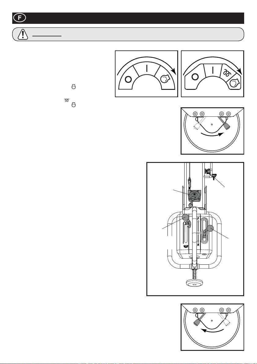
Procédure de Marche / Arrêt
ATTENTION
Avant d’allumer le moteur, assurez-vous que le Levier de Conduite est sur la position “Neutre”, le Levier de Vibration est sur “Arrêt” et
le Levier de Stationnement est sur “Marche”.
1. Ouvrez le robinet de carburant du moteur.
2. Actionner la poignée d’accélérateur vers la position
maximum (lapin)
3. Allumer le Moteur-Allumage Electrique
3ai. YANMAR - Placez l’interrupteur Clé du Levier de
Soupape sur la position Start
jusqu’au démarrage du moteur.
3aii. KUBOTA - Si le moteur est froid, maintenir la clef en
position de préchauffage
Soupape sur la position Start
NE PAS faire tourner le démarreur trop longtemps. 10 Secondes maximum.
3b. Après le démarrage du moteur, assurez-vous que la Clé est placée sur la position de
MARCHE (I) pendant l’operation. (Si l’Interrupteur Clé est placé sur “ARRET” (0), cela ne
permettrait pas le générateur de charger la batterie.
4. Démarrer le Moteur – Démarrage Manuel
4a. Prenez le lanceur en main.
4b. Retirez lentement jusqu’à ce que vous sentiez la résistance.
4c. Retournez lentement le lanceur à sa position initiale
4d. Poussez le décompresseur vers le bas, puis relâchez. La poignée retournera à sa position
initiale, une fois que le moteur a démarré.
4e. Prenez le lanceur en main
4f. Tirez le lanceur totalement, d’une façon forte et égale. Utilisez les 2
mains si nécessaire.
4g. Retournez lentement le lanceur à sa position initiale.
4h. Si le moteur ne démarre pas, répétez la procédure dès étape 4b.
5. Mettre le Levier de Soupape dans la position LOW, et laisser tourner le
moteur pendant quelques minutes pour se chauffer
6. Une fois le moteur chauffé la machine est prête pour une operation.
7. Déplacer le Levier de Stationnement vers la droite pour le désengager.
Mettre rapidement le levier de soupape à la position haute vitesse “H”
a¿ n d’éviter que l’embrayage ne soit pas endommagé.
La position “Soupape Pleine” de la machine a été pré-réglée à l’usine
a¿ n d’avoir une performance optimum de la machine.
NE PAS altérer ce réglage puisque cela peut povoquer l’usure
prématurée, ce qui annule automatiquement la garantie de la machine
ainsi que du moteur
8. Déplacer le Levier de Stationnement vers la droite pour le désengager
NOTICE: Négliger de désengager le Frein de Stationnement avant une
tentative de conduire la machine en avant ou en marche arrière, ocasionnera
de sérieux dommages au mécanisme du frein de stationnement ainsi qu’au
mécanisme de conduite.
9. Les commandes de l’operateur
9a. Levier de Soupape
Gardez toujours le Levier de Soupape dans la position “Haute”
pendant une opération. Ne tentez pas d’altérer la vitesse de
déplacement en changeant le nombre de tours du moteur.
9b. Levier de Conduite
Déplacez le Levier de Conduite en avant pour avancer. Pour la marche
arrière, poussez le levier en arrière.
9c. Levier vibration
En plaçant le Levier de Vibration à la position MARCHE, le mécanisme de vibration sera
engagé et va produire de vibrations.
10. L’ARRET
11. En préparation à l’arrêt du moteur, mettre le Levier de Soupape à la position “BAS”
12. Laisser le moteur tourner pendant 1 à 3 minutes
13. Mettre le Levier de Soupape dans la position d’ARRÊT pour arrêter le moteur. Puis, régler
l’Interrupteur Clé sur ARRÊT la sirène se déclenchera quand l’Interrupteur Clé est mis sur
MARCHE, alors que le moteur est arrêté.
14. Fermer le robinet du carburant
15. Activer le frein de stationnement en balançant le Frein de Stationnement vers la gauche.
NE PAS ENLEVER vos mains de la Manche de Démarrage pendant les procédures de Démarrage.
YANMAR KUBOTA
, et maintenez-le
pendant 10 secondes avant de démarrer Placez l’interrupteur Clé du Levier de
, et maintenez-le jusqu’au démarrage du moteur.
DESENGAGER
LEVIER
DE
SOUPAPE
LEVIER
DE
VIBRATION
ENGAGER
INTER-
RUPTEUR
CLE
LEVIER
DE
CONDUITE
38
Page 39

Fonctionnement des Rouleaux TDX
Ɣ Ayant effectué les véri¿ cations listées dans la section “pré-démarrage, vous pouvez allumer le moteur.
Les Rouleaux à Conduite Manuelle des Séries-TDX, du Altrad Belle sont équippés d’un embrayage centrifuge; cela permet de
laisser tourner le moteur sans conduire la Pompe hydraulique.
A mésure que la vitesse du moteur augmente l’embayage s’engage et le moteur pousse la Pompe Hydraulique à envoyer la
Ɣ
puissance hydraulique pour bouger les tambours ainsi que le méchanisme de vibration. A¿ n d’éviter toute dommage à
l’embrayage centrifuge, déplacez rapidement le levier de soupape de la position B à la H. Pour une opération bien menée, la
vitesse du moteur doit être réglée au maximum pendant l’opération de compactage.
Ɣ
Evitez d’utiliser la machine sur une surface dure, totalement compactée ou sans rendement.
Lorsque vous travaillez sur une pente raide, faites particulièrement attention pour faire marcher la machine a¿ n d’éviter qu’elle ne
Ɣ
s’écroule ou tombe. Travaillez toujours en amont et en aval de la pente. Ne travaillez pas à travers la pente. Si la machine est à
l’arrêt sur une pente, toujours appliquer le frein de stationnement.
Lorsque la machine est en marche arrière, assurez-vous de ne pas vous tenir debout derrière la Manche de Fonctionnement.
Ɣ
Marchez toujours le long de la Manche de Fonction, face tournée dans le sens de la marche.
Le Soulèvement
Ɣ
Dans le cas ou il est nécessaire d’utiliser un équipement pour positionner le TDX, assurez-vous que l’équipement de
soulèvement est doté d’une LCT (Limite pour le Chargement de Travail) qui correspond au poids de la machine (voir tableau
de spéci¿ cation) Attachez des chaines ou cordages adéquates UNIQUEMENT au point de soulèvement prévu au centre de la
machine (Crochet à point-unique) ou sur chaque coins de la machine (Points de Soulèvement).
TRANSPORT
Ɣ
Transport sur un véhicule.
Assurez-vous de la fermeture du timon et utilisez de bons dénivelés suf¿ sants en longueur, largeur et force pour le chargement
et déchargement du véhicule.
Appliquez le Levier de stationnement, et attachez fermement le véhicule pendant le transport.
Ɣ
Entretien
Maintenance
Les Rouleaux Compresseur à Conduite Manuelle de Altrad Belle, Séries-TDX sont conçus pour vous donner de normbreuses
années d’utilisation sans ennuis. Il est cependant important que la maintenance simple et régulière expliquée dans cette
section soit effectuée. On vous conseille de faire faire la maintenance et toute réparation par un concessionaire approuvé par
Altrad Belle. Utilisez toujours les vraies pièces de rechange de Altrad Belle. L’utilisation de fausses pièces pourrait annuler votre
garantie. Avant que toute maintenance soit effectuée sur la machine, éteignez le moteur et enlevez la clé de démarrage.
Posez toujours la machine au niveau du sol pour assurer que tous les niveaux de liquide soient correctement lus. Utilisez
uniquement les huiles conseillées (voir la page 41)
Véri¿ ez que le timon est replié de façon sûre pendant la maintenance et/ou les réparation.
Contrôle du Moteur
Faites le contrôle du moteur selon les spéci¿ cations du fabricants.
Référez-vous au manuel d’opération du moteur et de la maintenance.
NOTE: Quand la protection de maintenance a été déplacée, assurez-vous que tous les boulons soient correctement serrés au
moment de la remettre. Ne pas démarrer le moteur si les protections ne soient pas en bonne position.
Maintenance: Toutes les 8 heures ou quotidiennement
1. Recherchez des verrous et des écrous déserrés et reserrez-les.
2. Véri¿ ez et nettoyez l’élément de ¿ ltre d’air, relubri¿ ez-le conformément aux recommendations du fabricant du moteur. Si
les conditions de fonctionnement sont inhabituellement poussièreueses et séveres, le nettoyage d l’élément de ¿ ltre doit
s’effectuer plus fréquamment
3. Véri¿ er le niveau d’huile moteur avant l’opération.
Maintenance: Après 50 premières heures et toutes les 200 heures par la suite
1. Changer l’huile moteur - voir la procédure à la page 41.
39
Page 40
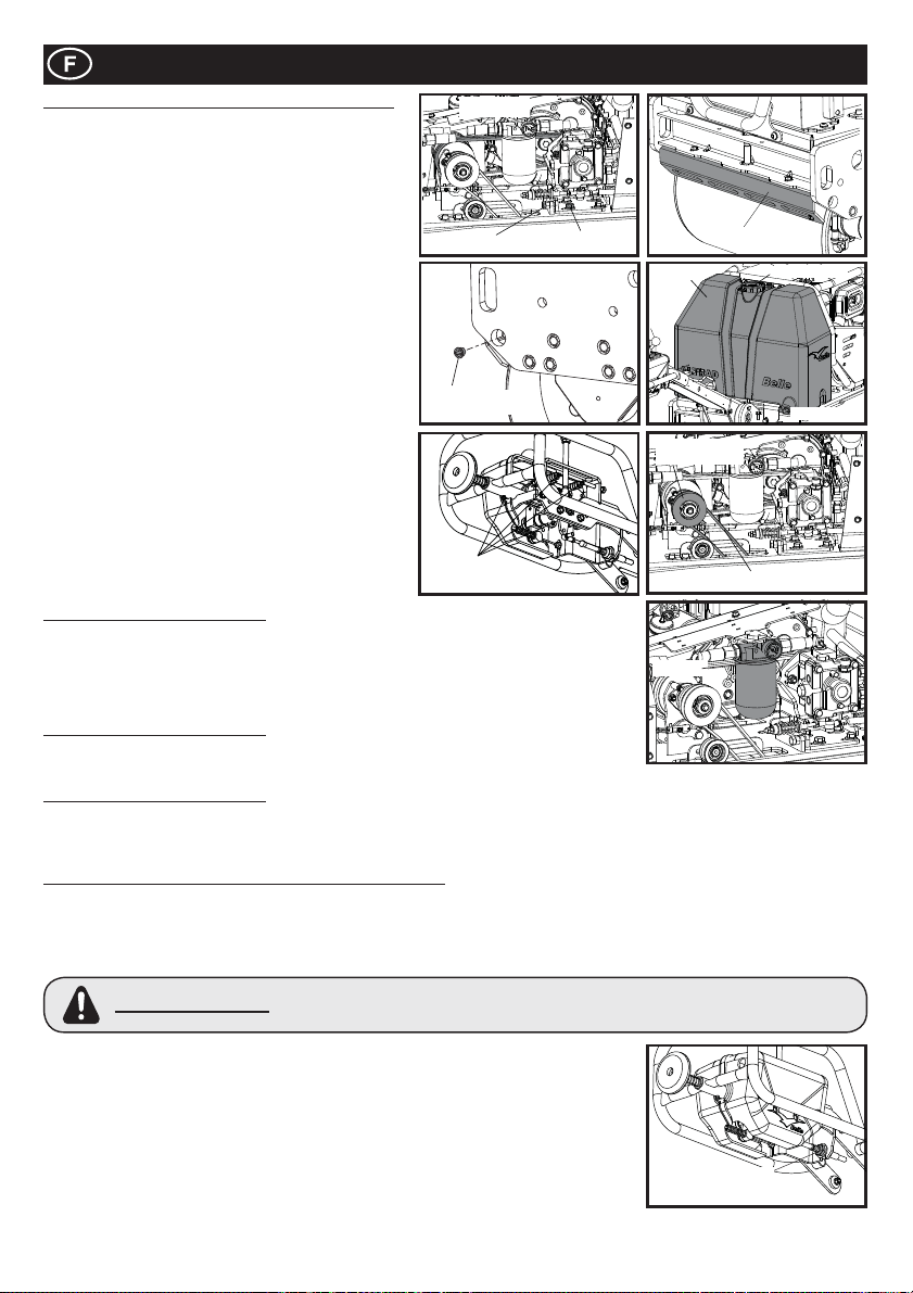
Entretien
La Maintenance toutes le 50 heures ou hebdomadaire
1. Véri¿ er la tension de la courroie
1a. Déserrez les verrous, qui ¿ xent le sillon de la pompe,
et tournez le Verrou : Ajuster jusqu’au moment ou la
tension adéquate est atteinte. La courroie devrait
dévier de 5mm au centre entre l’Embrayage Centrifuge
et la poullie de la Pompe.
1b. Reserrez les quatre écrous au niveau du Sillon de la
Pompe Quand la courroie est usée,¿ ssurée, renouvelez
la courroie.
2. Ajuster le dégagement du Racleur
2a. Enlevez le Racleur, et essuyez toute la terre, boue et le
goudron.
Ré-ajustez le Racleur au Sillon du Râcleur, et ¿ xez-le
2b.
avec suf¿ sament de dégagement (1mm) du tambour.
3. Réservoir d’eau
3a. Désamorcer le réservoir, et nettoyer l’intérieure par
un tuyau d’eau.
4. L’Ajustage de L’Arrroseur
4a. Enlevez le capuchon de l’ajustage, et nettoyez
l’intérieur de l’ajustage de L’Arroseur.
5. Moving Parts
5a. Le pièces qui bougent. Appliquez de la graisse
au bout de la tige du Cable de Conduite/Vibration.
Graissez les points de graissage sur le timon d’opération.
5b.
5c. Graisser l’arbre de vibrateur.
Maintenance: Tous les 100 heures
1. Mechanisme de L’Embrayage de Vibration.
1a. Véri¿ ez pour con¿ rmez que le Mechanisme de L’Embrayage de Vibration marche
correctement.
1b. Appliquez de la graisse dans les parties qui bougent.
1c. Véri¿ ez l’état de la Courroie-V. Lorsqu’elle est usée ou ¿ ssurée, renouvelez la.
Maintenance: Tous les 500 heures
1. Remplacez l’Elément de Filtrage Hydraulique d’Huile à
chaque 500 heures d’opération. Utilser du vrai Elément de Filtrage.
Maintenance: Tous les 800 heures
1. Changez L’Huile HydrauliqueRincez le réservoir avant d’y verser la nouvelle Huile Hydraulique. Pour expulser l’air du système
hydraulique laissez le Couvercle du Réservoir ouvert, et laissez tourner le moteur à sa vitesse maximum sans actionner le Levier
de Conduite et le Levier de Vibration pendant 10 minutes. Ensuite, remettez le Couvercle de Réservoir en place.
RÉGLAGE DU MONTAGE NEUTRE DU LEVIER DE CONDUITE
La position neutre du Levier de Conduite peut se modi¿ er grâce à la vibration ou l’usage des cable de conduite. Pour ajuster les
Réglages Neutres, suivez les unstructions ci-dessus ;
1. Placez la machine sur une surface plate
2. Assurez-vous que le moteur est éteinte.
3. Enlevez L’Ecrou qui ¿ xe le Bout de la Tige du Cable de Conduite au Levier de Conduite
Ne tentez pas de démarrer le moteur quand cet écrou n’est pas à sa place. La machine
AVERTISSEMENT
4. Desserrez L’Ecrou de Fermeture (de Serrure) au Bout de la Tige.
5. Tourner le Bout de Tige soit dans le sens des aguilles d’une montre ou dans le sens opposé
selon la direction de changement de la position neutre.
6. Re¿ xez le Bout de la Tige au Fil de Conduite et sécurisez-le avec un écrou.
7. Démarrez le moteur et augmenter les tours du moteur au maximum. Constatez si la position
neutre a été correctement ajustée.
8. Au cas ou c’est NON, arrêtez le moteur, et repétez les étapes 5 à 7 jusqu’au moment ou la
postion neutre est bien réglée.
9. Une fois que la position neutre a été correctement réglée, appliquez de la “Loctite” sur l’écrou,
ce qui ¿ xe le Bout de Tige, et serrez-le. Ensuite reserrez L’Ecrou de Ferméture.
peut bouger d’une manière irrationelle sans que l’on puisse la contrôler avec le Levier de
Conduite, ce qui peut causer des blessures ou des dommages aux biens
COURROIE
DE CONDUITE
AJUSTER COURROIE
CAPUCHON
D’ARROSAGE
POINTS DE
GRAISSAGE
BOULON
DE SILLON
RACLEURS
TANQUE
L’EMBRAYAGE
DE VIBRATION
COURROIE-V
FILTRE
L’ÉCROU DE
SÉCURITÉ
CAPUCHON
BOUCHON
40
Page 41
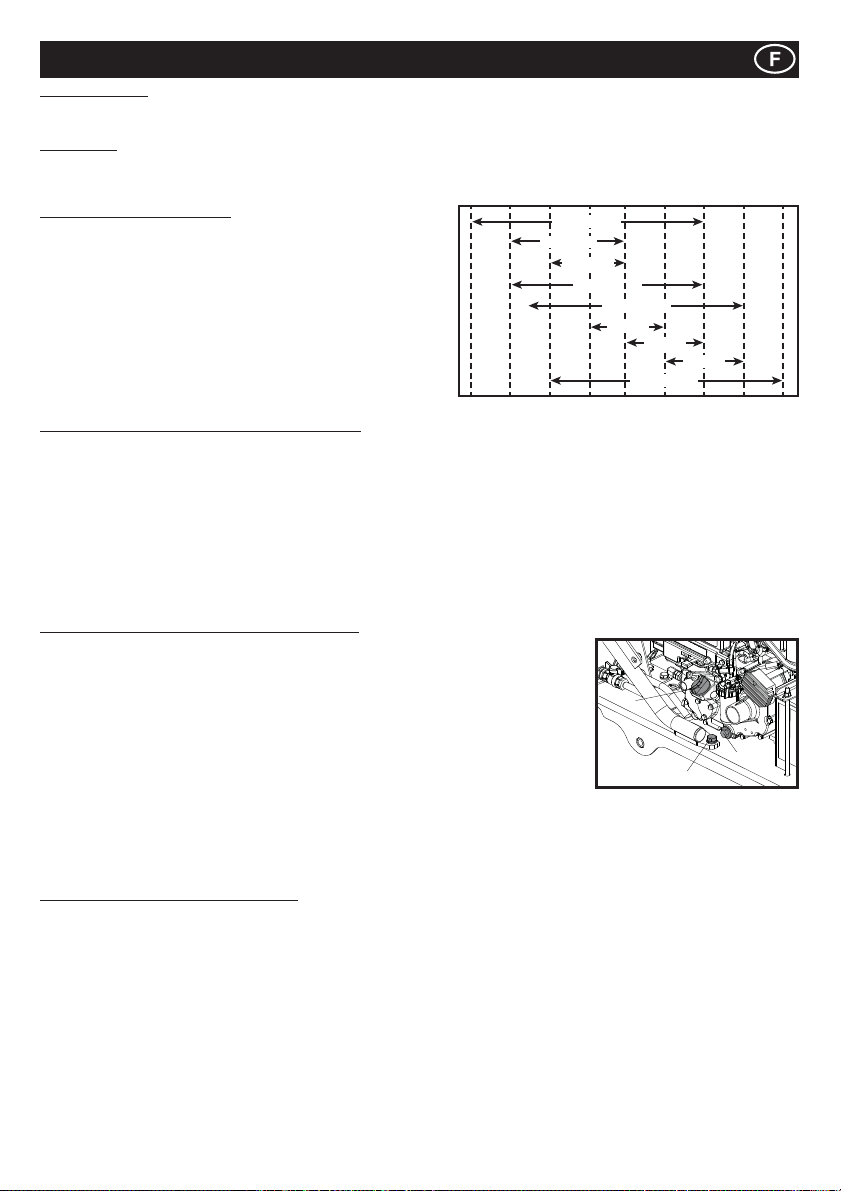
Entretien
Huile Hydraulique
Ɣ Total EP32, Shell Tellus T37, MOBIL DTE15 ou ESSO Unipower, XL46.
Huile moteur
Choisir la viscosité de l’huile moteur appropriée en fonction de la température ambiante et utiliser pour l’entretien le graphique de grade
de viscosité SAE ci-dessous. Cette machine est rempli de SAE 15W-40 à l’usine.
Spéci¿ cations de l’huile moteur
Utilisez une huile moteur qui respecte ou dépasse les lignes directrices
et les classi¿ cations suivantes
Catégories d’entretien
Ɣ Entretien API Catégories CD ou plus
Ɣ Entretien ACEA Catégories E-3, E-4 et E-5
Ɣ Entretien JASO Catégorie DH-1
Dé¿ nitions
Ɣ Classification API (American Petroleum Institute)
Ɣ Classification ACEA (Association des Constructeurs Européens
D’automobiles)
Ɣ JASO (Japanese Automobile Standards Organisation)
Procédure de changement de l’huile moteur - Yanmar
1. Véri¿ ez que le rouleau est sur une surface plane et que la poignée de commande est en position d’arrêt. Enclencher le frein de
stationnement.
2.
Desserrez l’écrou de la partie in férieure du bouchon de remplissage/vidange d’huile. NOTE: - NE PAS retirer le bouchon à ce stade.
3. Faites glisser le tuyau du panneau latéral.
4. Retirez les 4 vis M8 à l’aide d’une clé de 13 mm. Retirez le panneau latéral.
5. Inclinez le tuyau à l’extérieur du châssis, retirez le bouchon et vidanger l’huile dans un récipient.
6. Remontez le panneau latéral en utilisant une clé de 13 mm et faites glisser le tuyau de remplissage/vidange d’huile dans la fente du
panneau. Serrez l’écrou de ¿ xation sur le panneau latéral, mais ne refermez pas le bouchon.
7. À l’aide d’un entonnoir, versez de l’huile dans le tuyau de remplissage. Lors du remplissage veillez bien à ne pas dépasser la ca
pacité du réservoir. Utilisez une jauge sur le côté gauche du moteur pour véri¿ er le niveau d’huile.
8. Remettez le bouchon de remplissage/vidange d’huile.
9. Véri¿ ez que la machine fonctionne correctement.
30°F
(22°C)
(-20°C)
Procédure de changement de l’huile moteur - Kubota
1 Placez le timon en position de stockage et engager le frein de stationnement.
2. Monter le rouleau sur des blocs de 40mm, pour l’incliner du côté du bouchon de vidange.
3. Retirez les 4 vis M8 du capot latéral à l’aide d’une douille de 13 mm. Retirer le capot latéral.
4. À l’aide d’une clé 19mm retirer boulon M12 (1) du cadre du rouleau.
5. À l’aide d’une clé 17mm enlever le bouchon de vidange / ¿ ltre à huile (2) du moteur, pour
permettre à l’huile de vidange de s’écouler dans un récipient approprié.
6. Laver le bouchon de vidange / ¿ ltre à huile avec une huile légère et revisser sur le moteur.
Serrer à 50Nm.
7. Remontez le Boulon M12 (1) sur le cadre à l’aide d’une clé 19mm et serrer à 90Nm.
8. Retirez les blocs de 40mm sous le rouleau. Véri¿ ez que le rouleau est maintenant sur une
surface plane.
9. Retirez le bouchon de remplissage d’huile du moteur (3) et verser l’huile dans le moteur (1.3
Litres)
10. Revisser le bouchon de remplissage d’huile.
11. Fixer le capot de protection latérale du rouleau avec les 4 vis M8 à l’aide d’une douille de 13 mm. Serrer à 28Nm.
12. Désengager le frein de stationnement et abaisser le timon.
13. Véri¿ ez que la machine fonctionne correctement.
Procédure de Remplacement de la Batterie
1. Retirez les 4 x boulons du capot latéral en utilisant une douille de 13mm et retirer le capot.
2. À l’aide d’une clé de 11mm, retirez le câble de masse de la batterie puis retirez le câble positif.
3. Retirez la patte de ¿ xation et le tampon caoutchouc. Retirer les 2 x écrous et les 2 x rondelles à l’aide d’une clé 13mm.
4. Retirez la vis longue de maintien de la batterie et la rondelle avec une clé de 13mm.
5. Retirez les 2 x boulons du régulateur à l’aide d’une douille de 10mm.
6. Retirez le support qui se trouvait derrière le régulateur en utilisant une douille de 10 mm. Veiller à ne pas perdre l’entretoise derrière
le support.
7. Déplacez la sangle de retenue du câble À exible et tirer sur les ¿ ls.
8. Retirez la batterie et la remplacer par la nouvelle batterie.
9. Remettez les ¿ ls en place et ¿ xer-les avec la sangle de retenue.
10. Re¿ xez le support du régulateur et l’entretoise, et serrer à 12Nm.
11. Remontez les 2 x boulons dans le régulateur et serrer à 12Nm.
12. Remontez la longue vis de la batterie et la rondelle, et serrer à 28Nm.
13. Re¿ xez le tampon caoutchouc et la patte de ¿ xation de la batterie en utilisant une clé de 13mm. Serrer l’écrou pour assurer que
8mm de pas de vis ressortent.
14. Fixer le câble positif à la batterie, puis par le câble de masse.
15. Remontez la protection latérale. Serrer les 4 x boulons à 28Nm.
41
-4°F
SAE 10W
14°F
(-10°C)
SAE 5W-30
SAE 20W
SAE 10W-30
32°F
(0°C)
SAE 15W-40
SAE 20
SAE 30
SAE 20W-50
50°F
68°F
(10°C)
(20°C)
3
SAE 40
86°F
(30°C)
1
104°F
(40°C)
2
122°F
(50°C)
Page 42
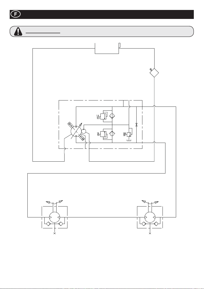
Circuit Hydraulique
AVERTISSEMENT
Si vous effectuez des reparations sur le circuit hydraulique, le bouchon du reservoir doit
etre enlevé de maniere a s’assurer que le systeme n’est plus pressurise.
42
Page 43
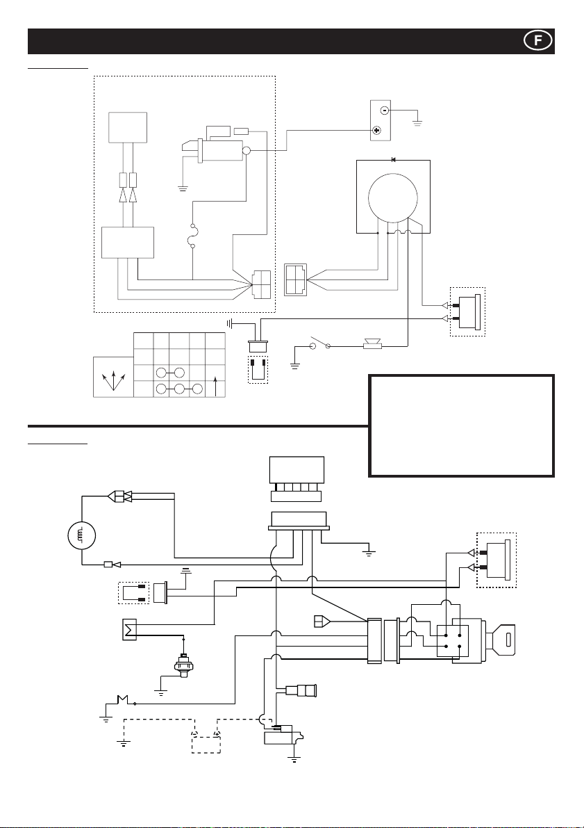
Yanmar L100NYanmar L100N
Schéma de câblage
Kubota EA330
12V - 15A
Dynamo
G/W G/W
CB104 CB104
CA104 CA104
G/W G/W
Regulateur
FONCTIONNEMENT DE LA CLÉ DE CONTACT
IG BAT ST NOTE
OFF12
OFF
1
2
Starter Moteur
DC12v 0.89Kw
W
JAS0
D601
20T
AUTO
Y
AV2 0
AV1 .25
AV1 .25
AV1 .25
AV2 0
M8
Vis
R
7323-2446
R
Y
B
BR
B
Heure Lien
d'Horloge Fil
WG
YAZAKI NO.
7322-2446
R
WG
Manocontacteur de pression
d’huile du moteur Sirène
Ter r e
YAZAKI NO.
W
G
Y
Batterie
Ter r e
Diode
Clé de contact
BAT
(30)
ST
IG
(25)
(50)
(15)
Y
G
R
W
Y
Option
d'Horloge
Heure
Inventaire
G = Vert IG = Allumage
W = Blanc BAT = Batterie
Y = Jaune ST = Demarrage
R = Rouge BK = Noir
Regulateur
BL = Bleu SB = Bleu Ciel
OR = Orange BR = Brun
Y
SBGBK
SB
R
Dynamo de
Ventilateur
Heure Lien
d’Horloge Fil
R
RonÀ eur
Interrupteur
Bougie
B
d’huile
BK/R
SB
BK
Y
Batterie
BR
BR
BR
Y
Y
R
Y
Y
W
W
BK/R
R
BK/W
Y
R
G
Interrupteur
de démarrage
Option d’Horloge
Heure
R
Fusible
Entrée
43
Page 44
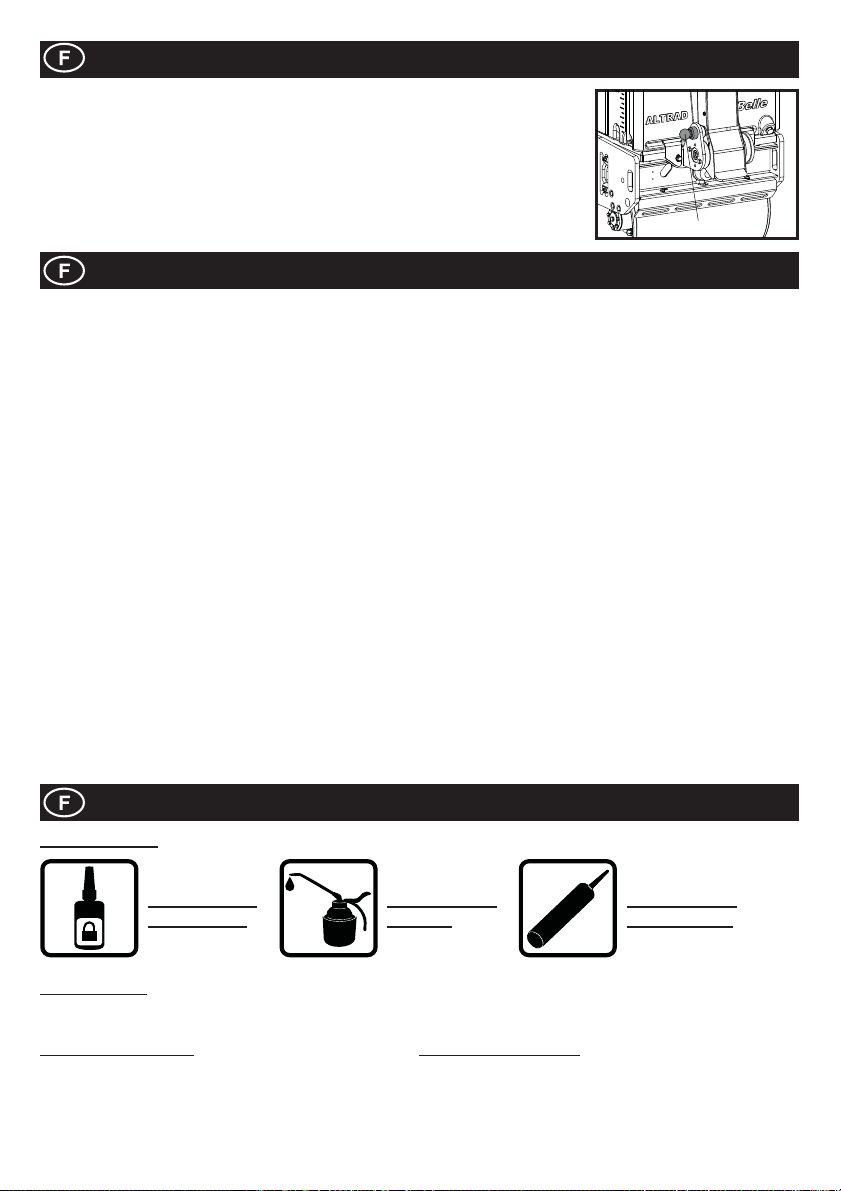
Stockage à long terme
1. Pour les longues périodes de stockage, vider le réservoir d’essence en aspirant le reste
d’essence par l’ori¿ ce de remplissage ou par le tuyau d’alimentation après avoir enlevé le
¿ ltre à essence.
2. Nettoyer le ¿ ltre à air.
3. Nettoyer l’huile at la poussière sur toutes les pièces en caoutchouc.
4. Nettoyer le plaque d’embase et appliquer de l’huile pour éviter la formation de rouille.
5. Couvrir la machine et la stocker un endroit sec.
6. Le timon peut être relevé pour le stockage. Déverrouiller le timon pour pouvoir le relever.
Véri¿ er que le timon soit verrouillé en position haute.
UN LOQUET
Garantie
Le Rouleau TDX de Altrad Belle est garantie à l’acquéreur d’origine un an (12 mois) à partir de la date originale de l’achat.
La garantie Altrad Belle s’applique à tous défauts de matériaux ou à un vice de conception ou de fabrication.
La garantie Altrad Belle ne couvre pas ce qui suit:
1. Dégâts causés par un usage abusif, négligent, une chute ou tous autres dégâts similaires causés par le non-respect des
instructions concernant l’assemblage, l’utilisation ou les opérations d’entretien à effectuer par l’utilisateur, ou résultant de celle-ci.
2. Toutes modi¿ cations, additions ou réparations effectuées par des personnes autres que les responsables de Altrad Belle ou
ses agents agréés.
3. Les frais de transport ou d’expédition pour retourner l’appareil à Altrad Belle, ou ses agents agréés, et le renvoyer, en vue de
le faire réparer ou évaluer après revendication sous garantie.
4. Les coûts des matériaux et/ou de la main-d’œuvre requis pour remplacer, réparer ou renouveler les composants en raison d’une
usure raisonnable.
Sont exclus de la garantie les composants suivants :
· Courroie(s) d’entraînement
· Filtre à air de moteur
· Bougie de moteur
Altrad Belle et/ou ses agents agréés, directeurs, employés ou assureurs ne sontpas tenus responsables de tous dégâts
conséquentiels ou autres, pertes oudépenses encourus en relation avec l’utilisation de l’appareil, ou l’incapacité d’utiliser l’appareil
dans un but quel qu’il soit.
Réclamations sous garantie
Il faut tout d’abord adresser toutes réclamations sous garantie à Altrad Belle par téléphone, fax, e-mail ou par courrier.
Pour les revendications sous garantie :
Prière d’écrire à :
Altrad Belle Warranty Department,
Sheen, Nr. Buxton,
Derbyshire
SK17 0EU
England.
Informations Pièces Détachées
INFORMATION
UTILISER DE
LA LOCTITE
Pour des informations concernant la disponibilité des Pièces de Détachées pour cette machine, veuillez s’il vous plaît aller sur
www.Belle247.com ou contacter ALTRAD Belle en utilisant les coordonnées suivantes :-
# - Options de Couleurs 1 ## - Options de Couleurs 2
Réf. + S = Orange (Eg. 981/05100S) Réf. + GR = Grey (Eg. 981/03200GR)
Réf. + G = Green Réf. + GR2 = Quartz Grey
Réf. + B1 = Blue Réf. + BL = Black
Réf. + R1 = Red Réf. + W = White
Réf. + Y = Yellow
Réf. + Y2 = Yellow
UTILISER DE
L’HUILE
44
SILICONE
UTILISER DE
LA SILICONE
Page 45
Como utilizar este manual
Este manual ha sido editado para ayudarle a usar y poner en servicio de manera segura el rodillo de compactación vibratorio de
manejo manual de la Marca Belle, Serie TDX 650A. Este manual está dirigido a distribuidores y usuarios de los modelo TDX 650A.
Avance
La sección “Medio Ambiente” da instrucciones de cómo manejar el reciclado de aparatos desechados de manera ecológica.
La sección “Descripción de la Máquina” ayuda a familiarizarse con el diseño y controles de la máquina.
Las secciones “Seguridad General” e “Higiene y Seguridad” explican cómo usar la máquina garantizando su seguridad y la del
público en general.
El “Procedimiento de Arranque y Parada” explica cómo arrancar y parar la maquina.
La guía “Solución de Problemas” ayuda a resolver algún tipo de problema en caso de que ocurriera.
La sección “Mantenimiento” ayuda con el mantenimiento general de su máquina.
La sección “Diagramas de Piezas y Listado” muestra los componentes detallados de su máquina y posiciones de los mismos en
caso de que hubiera necesidad de sustituir alguno.
Directivas en relación con el signi¿ cado
Los textos de este manual a los que hay prestar una atención especial se muestran del modo siguiente:
PRECAUCIÓN
Producto en posible peligro. La máquina o usted pueden sufrir daños si los procedimientos
no se siguen del modo correcto.
E
AVISO
AVISO
Antes de utilizar o realizar cualquier mantenimiento sobre esta máquina, DEBE LEER y ESTUDIAR este manual.
CONOZCA cómo usar de manera segura los controles de la unidad y lo que debe hacer para un mantenimiento seguro. (Nota:
asegúrese de saber cómo desconectar la máquina antes de conectarla, en caso de que surjan problemas).
Mantenga ó use SIEMPRE los elementos de seguridad adecuados necesarios para su protección personal.
Si le surge CUALQUIER PREGUNTA sobre el uso o mantenimiento adecuados de esta unidad,
PREGUNTE A UN SUPERVISOR Ó PÓNGASE EN CONTACTO CON LAS SIGUIENTES COMPAÑÍAS DEL GRUPO BELLE
(Inglaterra, Tel: +44(0)1298 84606)
Cómo usar este manual ...........................................................................................................................................................................45
Aviso .........................................................................................................................................................................................................45
Datos Técnicos ......................................................................................................................................................................................... 46
Pegatinas...........................................................................................................................................................................................47 - 48
Descripción de la máquina ....................................................................................................................................................................... 49
Seguridad general ....................................................................................................................................................................................49
Higiene y seguridad..................................................................................................................................................................................50
Comprobaciones antes del arranque .......................................................................................................................................................50
Medio Ambiente ........................................................................................................................................................................................50
Procedimiento de Arranque/Parada .........................................................................................................................................................51
Manejo del TDX 650A ..............................................................................................................................................................................52
Mantenimiento ...................................................................................................................................................................................52 - 54
Circuito hidráulico .....................................................................................................................................................................................55
Diagrama de cableado ............................................................................................................................................................................. 56
Almacenamiento prolongado .................................................................................................................................................................... 57
Garantia ....................................................................................................................................................................................................57
Información sobre las piezas de repuesto ............................................................................................................................................... 57
Declaracion de Conformidad ...................................................................................................................................................................... 2
La vida del operario puede encontrarse en peligro.
Aviso
Antes de operar ou de levar a cargo qualquer trabalho de manutenção, DEVERÁ LER e ESTUDAR
este manual.
Indice
E
E
45
Page 46
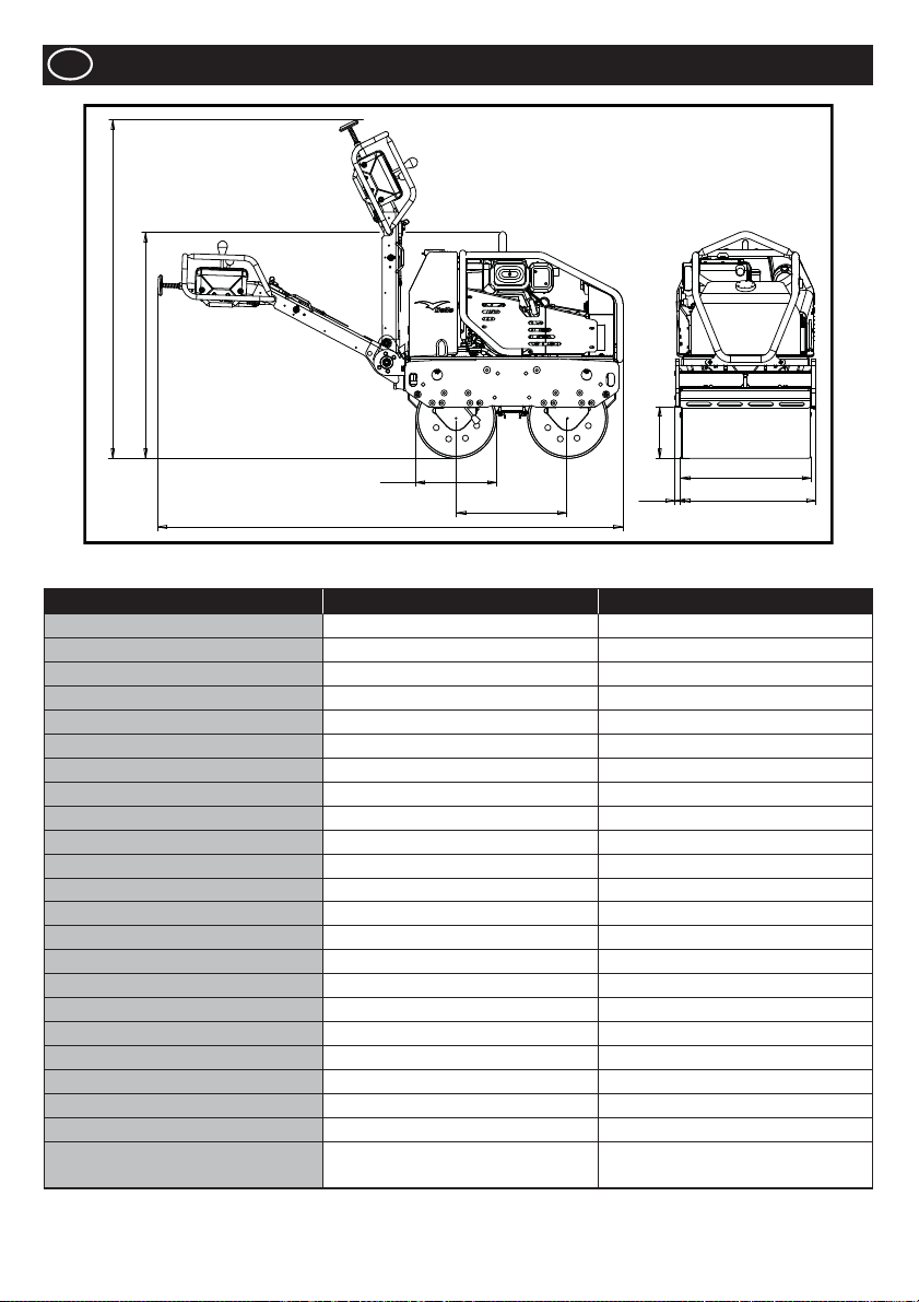
E
Datos Técnicos
J
B
G
D
A
Modelo TDX 650A Yanmar L100N TDX 650A Kubota EA330
Peso* - Kg 675 684
A - Longitud Total - mm 2318 2318
B - Altura Total - mm 1137 1137
C - Base del tambor - mm 560 560
D - Diámetro del tambor - mm 402 402
E - Anchura del tambor - mm 650 650
F - Anchura Total - mm 703 703
G - Altura Frontal Pie - mm 258 258
H - Saliente Lateral - mm 26.5 26.5
J - Altura Almacenaje - mm 1678 1678
Velocidad de ejecución Hacia delante - m/m (km/h)
Velocidad de ejecución Marcha atrás - m/m (km/h)
Frequencia de vibración - v.p.m 3300 3300
Fuerza centrífuga - kN 16 16
Capacidad del tanque de agua - Ltr 65 65
Capacidade del tanque de aceite - Ltr 16 16
Motor YANMAR L100N KUBOTA EA330
Tipo 4 Tiempos, Refrigerado Por Aire Refrigerado por agua, 4 tiempos
Combustible Diesel Diesel
Depósito de combustible - Ltr 5.4 4.8
Salida Nominal - Hp (kW) 9 (6.6) 5.9 (4.4)
Salida Máxima - Hp (kW) 10 (7.4) 6.9 (5.2)
Arranque
* Peso con el depósito de agua vacío. Capacidad del depósito de agua = 65 litros = 65 kg
Eléctrico (con la opción de copia de
seguridad de arranque de retroceso)
0 - 70 (0 - 4.2) 0 - 70 (0 - 4.2)
0 - 38 (0 - 2.3) 0 - 38 (0 - 2.3)
C
H
E
F
électrique
46
Page 47
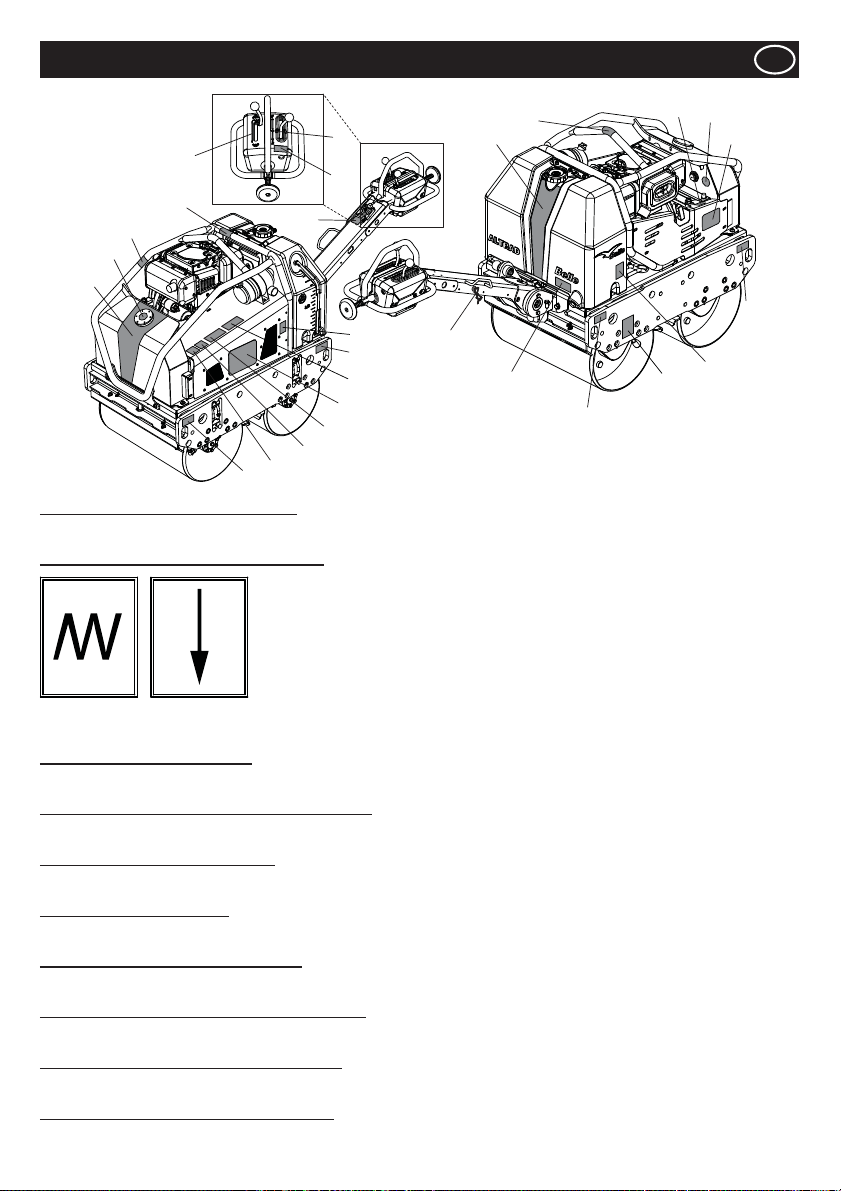
5
17
10
18
1
9
Números del 1 al 4 - Pegatinas de la marca
Pegatinas de la marca que identi¿ can el rodillo TDX.
Número 5 - Pegatina de la palanca de vibración
21
23
22
Pegatinas
7
6
8
9
25
3
24
Nota:- La ilustración muestra el modelo L100N Yanmar.
20
19
2
14
E
13
12
4
9
16
15
9
Vibración
activada
Número 6 - Pegatina de precaución
PRECAUCIÓN Lea el Manual del operador antes de utilizar la máquina.
Número 7 - Pegatina de la palanca de avance/retroceso
Palanca para cambiar la dirección de la máquina. F = Avance, R = Retroceso, Ɣ = Punto muerto.
Número 8 - Pegatina de mantenimiento
Indica que el dosel se puede retirar para llevar a cabo tareas de mantenimiento interno.
Número 9 - Pegatina de ¿ jación
Indica los puntos que pueden utilizarse para ¿ jar la máquina a una grúa para elevarla o para ¿ jarla durante el transporte.
Número 10 - Pegatina de super¿ cie caliente
PRECAUCIÓN
Número 11 - Pegatina de rellenado de aceite del motor
Indica el punto en el que se puede rellenar el aceite del motor y dónde se puede comprobar el nivel de aceite del motor.
Número 12 - Pegatina de nivel de aceite hidráulico
Indica la posición del indicador de aceite hidráulico, que muestra el nivel de aceite hidráulico del depósito.
Número 13 - Pegatina de tipo de aceite del motor
Especi¿ ca el tipo de aceite que se debe utilizar para rellenar el aceite del motor.
Vibración
desactivada
Tenga cuidado con las super¿ cies calientes que se encuentran alrededor del depósito hidráulico y de la zona de escape.
47
Page 48
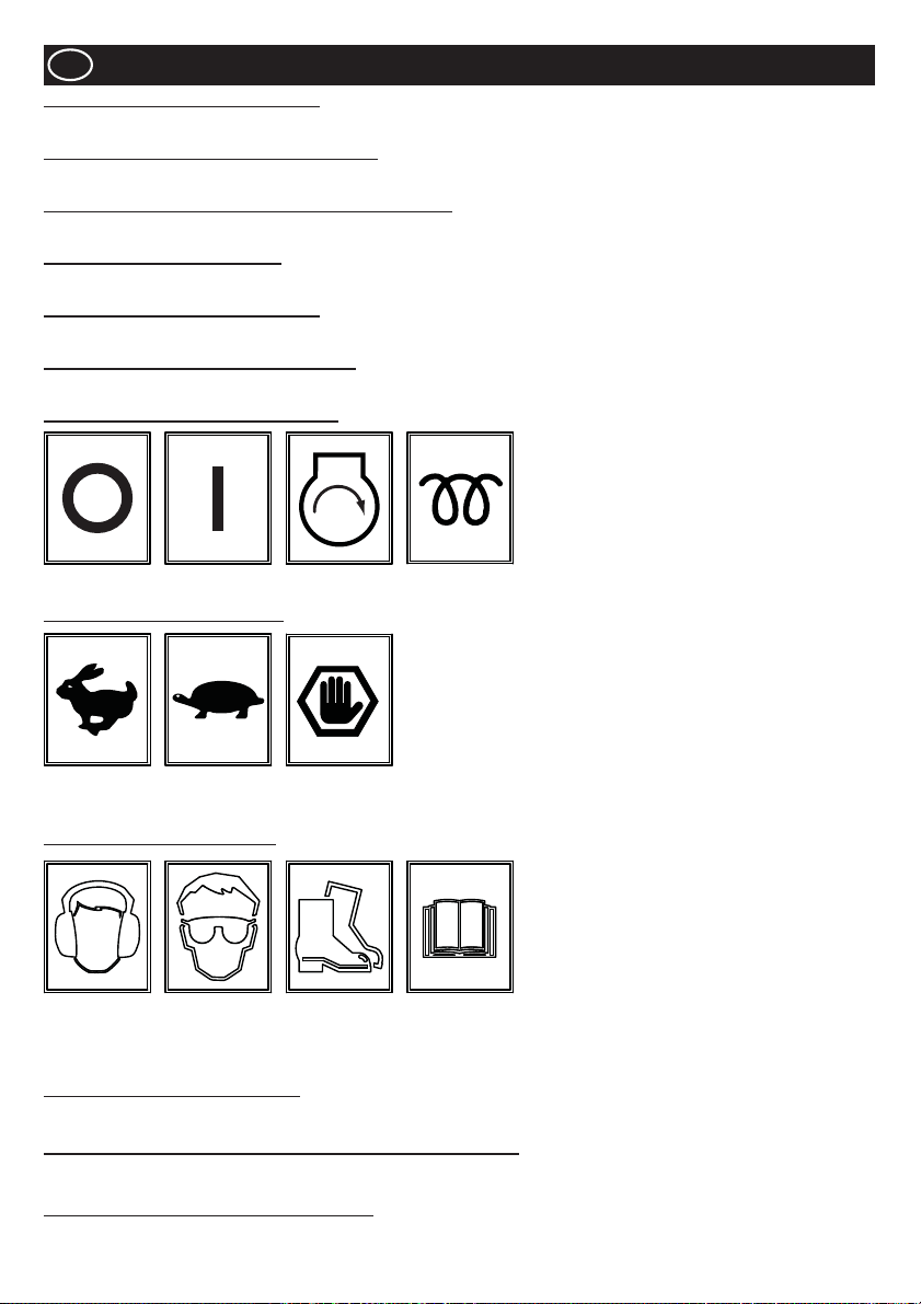
E
Número 14 - Pegatina de drenaje del agua
Si se prevé una temperatura ambiente bajo cero, debe drenarse el depósito de agua mediante el tapón de drenaje.
Número 15 - Pegatina de freno de estacionamiento
Muestra la posición del freno de estacionamiento. Debe aplicarse el freno de estacionamiento cuando la máquina no está en uso.
Número 16 - Pegatina de los grifos de los anillos de inyección
Muestra la posición de los grifos de los anillos de inyección, así como qué grifo corresponde a qué anillo.
Número 17 - Pegatina de solo diésel
Debe utilizarse SOLO diésel para el funcionamiento del motor.
Número 18 - Pegatina de aceite hidráulico
Indica la ubicación del tapón de llenado del aceite hidráulico.
Número 19 - Pegatina de argolla de suspensión
Indica la argolla de suspensión que puede utilizarse con una eslinga o un montacargas.
Número 20 - Pegatina de la llave de contacto
Pegatinas
APAGADO
Número 21 - Pegatina del acelerador
Posición de
RPM máx.
Número 22 - Pegatina de seguridad
Utilice
protección
auditiva
Número 23 - Pegatina de nivel de ruido
Nivel de potencia de sonido garantizado de la máquina en dB(A).
Número 24 - Pegatina de aviso de gases de escape (pieza n.º 800-99520)
Los motores emiten monóxido de carbono. Utilizar solo en zonas con buena ventilación.
Número 25 - Pegatina de peligro de aplastamiento
PRECAUCIÓN Tenga cuidado con los componentes mecánicos, si se retira la guardia.
ENCENDIDO
Posición de
ralentí
Utilice
protección
ocular
ARRANQUE
Posición de
parada de
emergencia
Utilice
calzado de
seguridad
CALOR
(KUBOTA)
Lea el
Manual del
operador
48
Page 49
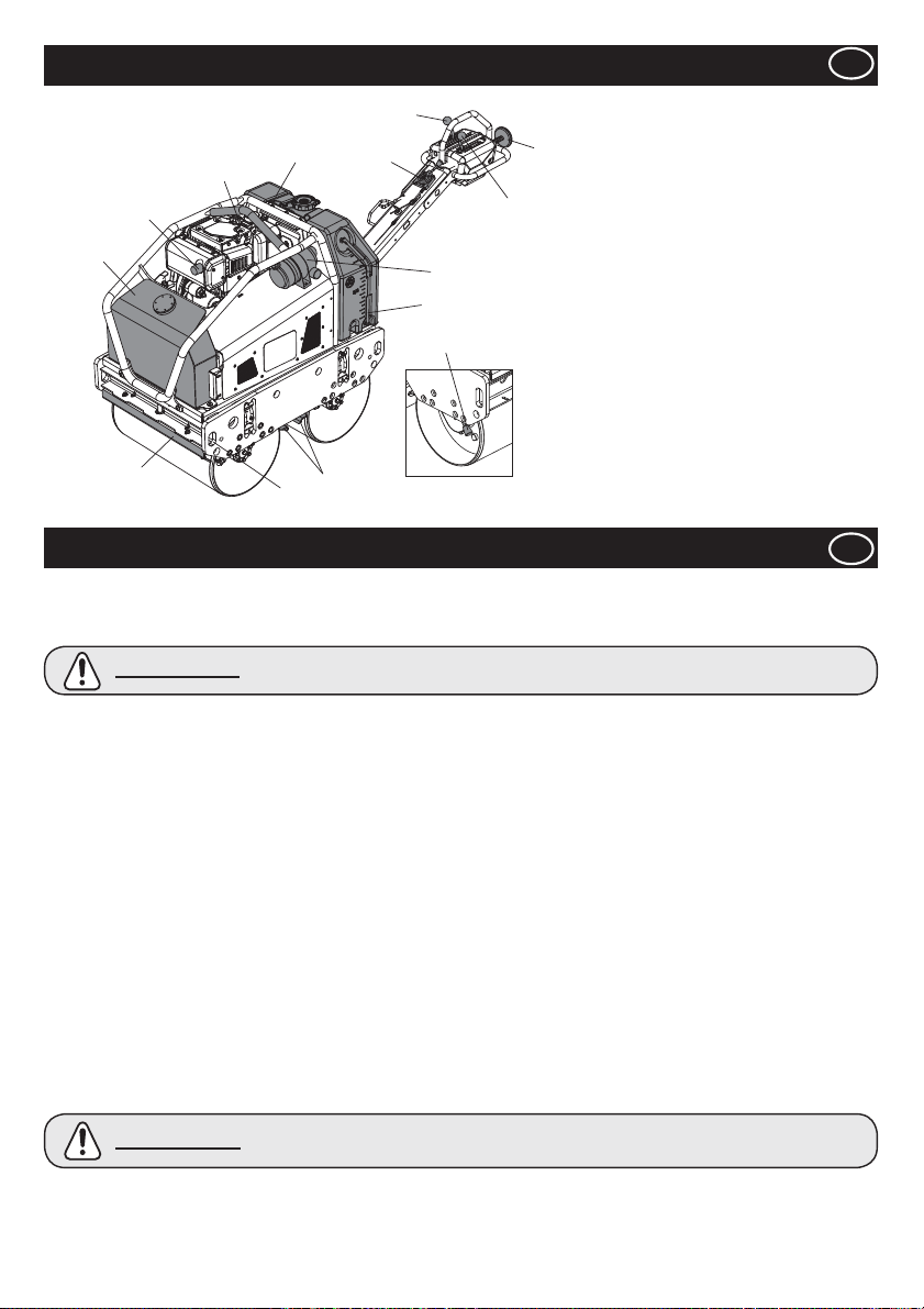
Descripción de la máquina
5
1. Depósito de aceite hidráulico.
2
12
1
10
4
11
8
3
9
13
10
7
2. Argolla de suspensión
6
3. Filtro de aire
4. Depósito de agua.
5. Palanca de avance / Marcha atrás.
6. Palanca de Vibración.
7. Palanca de seguridad sentido marcha atrás.
8. Palanca Embrague.
9. Indicador de nivel del agua
10. Barras de arrastre
11. Puntos de ¿ jación
12. Escape
13. Freno de estacionamiento
Nota:- La ilustración muestra el modelo L100N
Yanmar.
E
Seguridad General
Para su propia protección y seguridad de los que le rodean, por favor lea y asegúrese de que ha comprendido la información sobre
seguridad que a continuacion se explica. Es responsabilidad del operario estar seguro de que entiende en su totalidad cómo manejar
este equipo de modo seguro. Si se siente inseguro sobre la seguridad y el uso correcto de su TDX 650A, consulte a un supervisor o a
las compañías del Altrad Belle.
PRECAUCIÓN
Esta máquina solo debe usarse para su objetivo previsto.
Ɣ
Ɣ
Esta máquina solo debe ser manejada por personal bien entrenado.
Ɣ
El propietario de esta máquina debe cumplir y enseñar al usuario de que cumpla, la Normativa de Protección Laboral en
vigor en el país de aplicación.
Ɣ
Utilice un equipo de elevación adecuado para levantar la máquina
Esta máquina debe utilizarse en un suelo donde se garantice la estabilidad. Cuando se trabaje cerca del borde de zanjas
Ɣ
excavadas, utilice adecuadamente la máquina para que no se bloquee o caiga.
Si la super¿ cie a compactar está en una pendiente, tenga mucho cuidado cuando controle la dirección de marcha de la máquina.
Ɣ
Acordone la zona de trabajo y mantenga a las personas no autorizadas en una distancia de seguridad.
Ɣ
El operario debe llevar Equipo de Protección Personal (EPP) siempre que use esta unidad (Ver Higiene y Seguridad).
Ɣ
Ɣ
Asegúrese de que sabe cómo desconectar con seguridad esta máquina antes de conectarla en caso de que tenga di¿ cultades.
Siempre que la maquina no esté en servicio debe permanecer desconectada.
Ɣ
Durante su uso, el motor se calienta mucho. Deje que se enfríe antes de tocarlo.
Ɣ
Ɣ
Nunca deje la máquina en funcionamiento y desatendida.
Nunca retire las protecciones instaladas. Compruebe siempre el estado y la seguridad de las protecciones. Si hay alguna
Ɣ
dañada o falta, NO UTILICE LA MÁQUINA hasta que la protección haya sido sustituida o reparada.
No maneje nunca la máquina cuando se encuentre enfermo, cansado, o bajo la acción de alcohol o drogas.
Ɣ
Ɣ
Esta máquina ha sido diseñada para eliminar los posibles riesgos derivados de su uso. Sin embargo, EXISTEN riesgos y
estos peligros residuales no son claramente reconocibles y pueden causar lesiones personales o daños a la propiedad y
muerte posible. Si se detectan estos riesgos impredecibles o irreconocibles, se debe detener inmediatamente la máquina y
bien el operario ó su supervisor deben tomar las medidas adecuadas para eliminar dichos riesgos. En ocasiones es necesario
informar al fabricante sobre dicho suceso para futuras contra medidas.
Seguridad del Combustible
PRECAUCIÓN
Antes de repostar, apague el motor y deje que se enfríe.
Ɣ
Ɣ
Cuando esté repostando, NO FUME ni permita llamas desnudas en la zona.
Ɣ
Cuando reposte, utilice el embudo adecuado y evite derramar combustible sobre el motor.
Ɣ
El combustible derramado debe cubrirse inmediatamente con arena. Si se derrama combustible en su ropa, cámbiesela.
Ɣ
Almacene el combustible en un contenedor autorizado fabricado al efecto, lejos de fuentes de calor o ignición.
Un mantenimiento inadecuado puede ser peligroso. Lea y entienda esta sección antes de realizar
cualquier mantenimiento, servicio o reparación.
O combustível é inÀ amável. Pode causar lesões e danos patrimoniais. Desligar o motor, extinguir
qualquer chama nua e não fumar enquanto encher o depósito de combustível. Limpar sempre
qualquer derrame de combustível.
E
49
Page 50
E
Vibración
Parte de la vibración de la operativa de las máquinas se trasmite a través del asa a las manos del operador. El Rodillo de
compactacion vibratorio de Dirección Manual, Serie TDX 650A, del Altrad Belle ha sido diseñado especí¿ camente para reducir los
niveles de vibración Mano/Brazo. Remítase a las especi¿ caciones y datos técnicos para ver los niveles de vibración y los tiempos
de uso (tiempo de exposición diario máximo recomendado).
EPP (Equipo de Protección Personal)
Se debe llevar el EPP adecuado cuando se utilice este equipo, por ejemplo Gafas de Seguridad, Guantes, Protectores para
los oídos, Mascara Anti-polvo y calzado con protección de acero para los pies. Lleve la ropa adecuada para el trabajo que está
realizando. Recoja el pelo largo y quítese cualquier objeto que pueda engancharse en las piezas móviles del equipo.
Polvo
El proceso de compactación puede producir polvo, que puede ser peligroso para su salud. Lleve siempre una máscara adecuada al
tipo de polvo que se vaya a producir.
Combustible
No ingiera combustible ni inhale vapores de combustible y evite el contacto con su piel. Lávese inmediatamente las salpicaduras
de combustible. Si le entra combustible en los ojos, láveselos con abundante cantidad de agua y busque atención médica lo antes
posible.
Gases de escape
No use su máquina en interiores o espacios cerrados, asegúrese de que la zona de trabajo está bien ventilada.
AVISO
Los gases de escape producidos por este equipo son altamente tóxicos pudiendo provocar
incluso la muerte.
Higiene y Seguridad
E
Inspección Previa al Arranque
La siguiente inspección previa al arranque debe ser realizada antes de empezar cada sesión de trabajo ó después de cada cuatro
horas de uso. Por favor, remítase a la sección de Mantenimiento para la guía detallada. Si se descubre cualquier avería, no se deberá
usar la máquina hasta que se arregle.
1. Inspeccione cuidadosamente la máquina para buscar signos de daños.
2. Compruebe las manguitos, las aperturas de llenado, tapones de drenaje y cualquier otra zona en busca de posibles pérdidas.
Fije cualquier pérdida antes de la operación.
3. Compruebe el aceite del motor y rellene según sea necesario.
3a. Coloque la máquina en una super¿ cie nivelada y compruebe el nivel de aceite de la máquina.
3b. Quite la medida del aceite y fíjese en que éste llega al borde de la marca de relleno. Utilice el aceite de motor adecuado con
la viscosidad adecuada (Consulte el grá¿ co de grado de viscosidad del servicio SAE en la sección Servicio)
4. Compruebe el nivel de combustible del motor y rellene según sea necesario. Utilice combustible limpio. El uso de combustible
contaminado puede dañar el sistema de combustion.
5. Veri¿ que que el ¿ ltro de aire está limpio.
La acumulación excesiva de polvo/suciedad dentro del componente del ¿ ltro puede ser causa de funcionamiento incorrecto del
motor. Limpie el componente del ¿ ltro de aire cuando esté sucio (Ver sección de Mantenimiento).
6. Compruebe el funcionamiento de los Controles de la maquina.
Asegúrese de que la Palanca de Dirección, la Palanca de Vibración, la Palanca de embrague, la Palanca de Estacionamiento
y el Dispositivo de Seguridad para el sentido marcha atrás se mueven con suavidad.
7. Revise el nivel de refrigerante del motor. La reposición hasta el nivel “llenar” si es necesario - KUBOTA SOLAMENTE!
E
Eliminación segura
Instrucciones para la protección del medio ambiente.
La máquina monta materiales de valor. Lleve el
aparato desechado y sus accesorios a las
instalaciones de reciclado correspondientes.
Comprobaciones previas al Arranque
Medio Ambiente
Componente Material
Manivela Acero
Bastidor Principal Acero
Depósito de aceite Hidráulico Acero
Depósito de agua Polietileno
Cubierta Polietileno
Bomba Hidráulico Acero y Aluminio
Motor Hidráulico Acero
Motor Acero y Aluminio
Otras Piezas Acero, Aluminio e caucho
50
Page 51
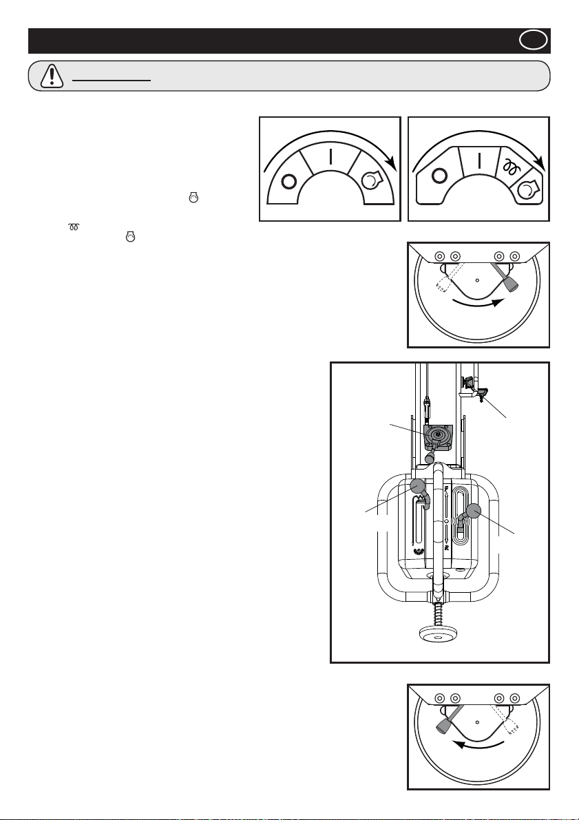
Procedimiento de Arranque/Parada
E
PRECAUCIÓN
Antes de arrancar com o motor, con¿ rmar que o Comando do Sentido de Marcha está no Ponto Morto, o Comando de Vibração
está desligado (OFF) e o Travão de Estacionamento está accionado (ON).
1. Abra el grifo de combustible del motor.
2. Desplace la palanca del acelerador situada en la
empuñadura de funcionamiento a la posición de
aceleración máxima (liebre).
Arranque del motor - Arranque eléctrico
3ai. YANMAR del acelerador a la posición Arranque y manténgalo
en esta posición hasta que arranque el motor.
3aii.
KUBOTA - Desde fresco, mantener la posición
calor
la posición Arranque
NO arranque durante un período de tiempo prolongado. (máximo de 10 segundos).
3b. Una vez ha arrancado el motor, asegúrese de que la llave está en la posición ENCENDIDO
(I) durante la operación (si el interruptor de arranque se encuentra en la posición APAGADO
(0), el generador no puede cargar la batería).
Arranque del motor - Arranque manual
4a. Tome la manecilla de arranque manual.
4b. Tire de la manecilla hacia fuera lentamente hasta que note una gran resistencia.
4c. Devuelva lentamente la manecilla de arranque manual a la posición inicial.
4d. Baje la palanca de descompresión y, a continuación, suéltela. La palanca de descompresión
vuelve automáticamente a su posición original cuando el motor arranca.
4e. Tome la manecilla de arranque manual.
4f. Tire de la manecilla hacia fuera con un movimiento ¿ rme y continuo.
Utilice las dos manos si es necesario.
4g.
Devuelva lentamente la manecilla de arranque manual a la posición inicial.
4h. Si el motor no arranca, repita el procedimiento a partir del paso 4b.
5. Desplace la palanca del acelerador a la posición LOW y deje que el
motor funcione en ralentí durante unos minutos para calentar.
6. Cuando el motor se ha calentado, la máquina está lista para el
funcionamiento.
7. Desplace la palanca del acelerador a la posición de velocidad alta
“H” rápidamente para evitar que se produzcan daños en el embrague.
La posición “a todo gas” de la máquina está con¿ gurada de fábrica para
conseguir un rendimiento óptimo de la máquina.
NO modi¿ que esta con¿ guración, ya que podría producirse un desgaste
o una rotura prematura y tanto la garantía del motor como la de la
máquina se anularían automáticamente.
8. Desplace la palanca del freno de estacionamiento hacia la derecha para
desacoplarlo.
NOTA: si no se desacopla el freno de estacionamiento antes de operar la
máquina tanto en avance como en retroceso, se producirán daños
graves en el mecanismo del freno de estacionamiento y en el
sistema de transmisión.
9. Controles del operador
9a. Palanca del acelerador
Mantenga siempre la palanca del acelerador en la posición de velocidad
alta durante la operación. NO intente modi¿ car la velocidad de marcha
cambiando las revoluciones del motor.
9b. Palanca de mando
Mueva la palanca de mando hace delante para conducir la máquina
hacia delante. Para la marcha atrás, mueva la palanca hacia atrás.
9c. Palanca de vibración
Desplace la palanca de vibración a la posición ENCENDIDO para activar el mecanismo de vibración
10. Parada del motor
11. Para preparar la máquina para la parada del motor, desplace la palanca del acelerador a la
posición de velocidad baja.
12. Deje que el motor funcione en ralentí durante 1-3 minutos.
13. Mueva la palanca del acelerador a la posición PARADA para parar el motor. A continuación,
desplace el interruptor de arranque a la posición APAGADO. El zumbador sonará si el
interruptor de arranque se desplaza a la posición ENCENDIDO cuando el motor está parado.
14. Cierre el grifo de combustible.
15. Aplique el freno de estacionamiento desplazando la palanca del freno de estacionamiento
hacia la izquierda.
Gire el interruptor de arranque de la palanca
durante 10 segundos.
Producto en posible peligro. La máquina o usted pueden sufrir daños si los procedimientos
no se siguen del modo correcto.
YANMAR KUBOTA
Gire el interruptor de arranque de la palanca del acelerador a
y manténgalo en esta posición hasta que arranque el motor.
DESACOPLAR
PALANCA
DEL
ACELERADOR
PALANCA DE
VIBRACIÓN
INTERRUPTOR
DE ARRANQUE
ACOPLAR
PALANCA
DE MANDO
51
Page 52

E
Ɣ Una vez que se hayan realizado las comprobaciones enumeradas en la sección “previo al arranque”, se puede arrancar el
motor.
Los apisonadores de dirección manual de la serie TDX del Grupo Belle, tienen instalado un embrague centrífugo que permite
que el motor funcione en punto muerto sin que la bomba hidráulica funcione.
A medida que aumenta la velocidad del motor, el embrague se enganchará y el motor activará la bomba hidráulica para trasmitir
Ɣ
energía hidráulica a los tambores, así como el mecanismo del vibración. Para evitar cualquier daño al embrague centrífugo,
mueva rápidamente la palanca de embrague desde la posición L hasta la H. Para un funcionamiento correcto, la velocidad del
motor debe ponerse al máximo durante la operación de compactación.
Ɣ
Evite usar la máquina sobre una super¿ cie totalmente compactada, dura o resistente. De lo contrario, los cojinetes y otros
componentes mecánicos se dañarán y se reducirá mucho la vida de la máquina.
Ɣ
Cuando trabaje en una pendiente pronunciada, preste especial atención a la operación de la máquina para que esta no se deslice
pendiente abajo.
Trabaje siempre subiendo o bajando la pendiente. No trabaje en perpendicular con respecto a la pendiente. Si la máquina está
estacionada en una pendiente, accione siempre el freno de estacionamiento.
Cuando la máquina vaya marcha atrás, asegúrese de que no se encuentra detrás de la manivela de operación. Camine
Ɣ
siempre a lo largo de la manivela de operación y mire en la dirección del movimiento.
Elevación
Ɣ
En caso de que sea necesario utilizar equipos de elevación para posicionar el TDX 650A, asegúrese de que el equipo de elevación
tiene un LCT (límite de carga de trabajo) adecuado para el peso de la máquina (consulte la tabla de Datos técnicos). Fije las
cadenas o eslingas adecuadas SOLO en los puntos de suspensión ubicados en el centro de la máquina (argollas de suspensión) o
en las esquinas de la máquina (puntos de ¿ jación) a tal efecto.
TRANSPORTE
Ɣ
Transporte sobre un vehículo.
Asegúrese de bloquear la Manivela y usar rampas de su¿ ciente anchura, longitud y fuerza cuando cargue y descargue el vehículo.
Antes de llevar a cabo tareas de mantenimiento en la máquina, apague el motor y retire la llave del interruptor de arranque.
Ɣ
Funcionamiento de los Apisonadores TDX
E
El Rodillo de Compactacion Vibratorio de Dirección Manual, Serie TDX del Altrad Belle ha sido diseñado para proporcionar muchos
años de funcionamiento sin problemas. Sin embargo, es importante que se realice el mantenimiento simple periódico que se
explica en esta sección. Se recomienda que sea un distribuidor autorizado por Altrad Belle quien realice todas las reparaciones y
mantenimiento principales. Use siempre piezas de repuesto originales del Grupo Belle, el uso de piezas falsas puede anular su
garantía. Antes de cualquier operación de mantenimiento se lleva a cabo en la máquina, apague el motor y retire la llave del interruptor
de llave
Coloque siempre la máquina en suelo nivelado para asegurar que se leen bien los niveles de los liquidos. Use unicamente aceites
recomendados (Consulte la página 54).
Mantenimiento del Motor
Realice el mantenimiento del motor según las especi¿ caciones del fabricante.
Remítase al manual de operación y funcionamiento del motor.
Nota: Cuando la Tapa de Mantenimiento ha sido retirada, asegurarse de que todas todas las tuercas han sido apretadas con
seguridad antes de que sea nuevamente colocada. NO encienda el equipo con los protectores retirados.
Mantenimiento: cada 8 horas o diariamente
1. Compruebe si hay tornillos o tuercas sueltos. Apriete si es necesario.
2. Compruebe y limpie el componente del ¿ ltro de aire, lubrique de nuevo el componente siguiendo las recomendaciones del
fabricante del motor. Si las condiciones de trabajo son especialmente polvorientas y duras, la limpieza del componente del ¿ ltro
de aire debe hacerse más frecuentemente.
3. Comprobar el nivel de aceite del motor antes de la operación.
Mantenimiento: Después de las primeras 50 horas y cada 200 horas a partir de entonces
1. Cambie el aceite del motor - véase el procedimiento en la página 54.
Mantenimiento
52
Page 53
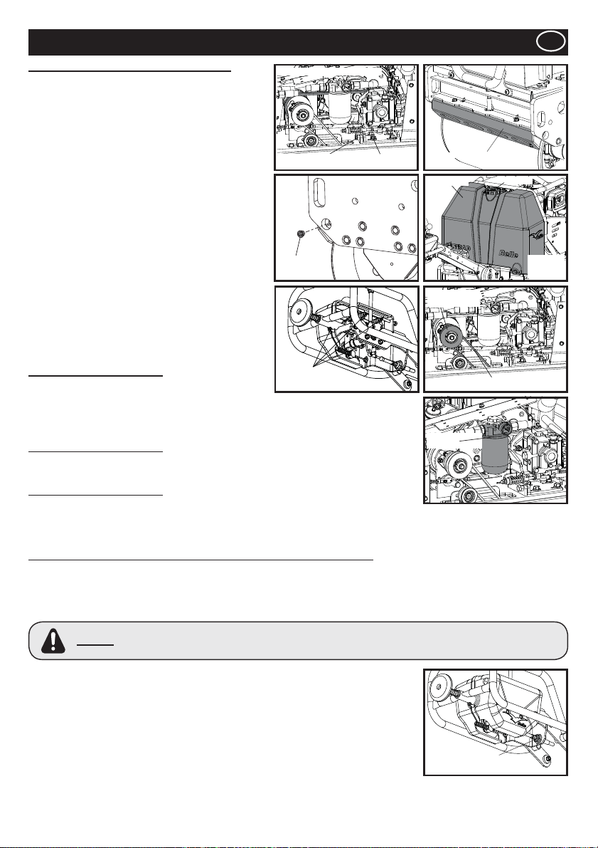
TAPÓN
E
TAPON
DE
VACIADO
Mantenimiento
Mantenimiento: cada 50 horas o semanalmente
1. Compruebe la tensión de la correa de transmisión
1a. AÀ oje cuatro tornillos, que ¿ jan la Palanca de la Bomba
y gire el Tornillo de ajuste hasta que se consiga la
tensión adecuada. La correa debe desviarse unos 5mm
del centro entre el embrague centrífugo y la polea de la
bomba.
1b. Apriete los cuatro tornillos en la palanca de la bomba.
2. Ajustar la separación del Raspador
2b. Quite el Raspador y limpie el polvo, el lodo y el asfalto.
2c.
V
uelva a colocar el Raspador en su Abrazadera y
colóquelo con la su¿ ciente distancia del tambor.
3. Depósito de Agua
3a. Drene toda el agua y limpie el interior del tanque con
una manguera.
4. Boquilla del Sprinkler
4a. Quite el tapón de la boquilla y limpie el interior de la
boquilla del sprinkler.
5. Piezas móviles
5a. Engrase el extremo de la varilla del Cable de
Dirección/Vibración.
5b. Engrase de nuevo los puntos correspondientes de la
empuñadura de funcionamiento.
5c. Engrase el eje del vibrador
Mantenimiento: cada 100 horas
1. Mecanismo del embrague de vibración
1a. Veri¿ car que el mecanismo del embrague de vibración
funciona correctamente.
1b. Engrasar la pieza móvil.
1c. Comprobar el estado de la correa-V. Cuando esté desgastada o agrietada, renovarla.
Mantenimiento: cada 500 horas
1. Cambiar el componente del ¿ ltro del aceite hidráulico después de cada 500 horas de
funcionamiento Emplee un componente de ¿ ltro original.
Mantenimiento: cada 800 horas
1. Cambiar el aceite hidráulico. Limpie el depósito antes de llenarlo de aceite hidráulico nuevo.
Para purgar el aire del sistema hidráulico, deje abierta la Tapa del depósito, y haga
funcionar el motor hasta su velocidad máxima sin activar la Palanca de Dirección y la
Palanca de Vibración durante 10 minutos. A continuación, vuelva a colocar la Tapa del Depósito.
AJUSTE DE LA POSICIÓN DE PUNTO MUERTO DE LA PALANCA DE DIRECCIÓN
La posición de punto muerto de la Palanca de Dirección puede estar desplazada debido a la vibración o el desgaste de los cables de
dirección. Para ajustar la posición de punto muerto, siga las instrucciones siguientes:
1. Coloque la máquina en una super¿ cie nivelada.
2. Asegúrese de que el motor está apagado.
3. Quite la tuerca que ¿ ja el extremo de la varilla del Cable de Dirección a la Palanca de Dirección.
No intente arrancar el motor cuando esta tuerca está fuera de su posición. La máquina puede moverse
AVISO
4. AÀ oje la tuerca de bloqueo del extremo de la varilla.
5. Gire el extremo de la varilla en el sentido de las agujas del reloj o contra las agujas del reloj,
según la dirección del desplazamiento de la posición de punto muerto.
6. Vuelva a colocar el extremo de la varilla en el Cable de Dirección y apriételo con una tuerca.
7. Arranque el motor y aumente sus revoluciones hasta el máximo. Compruebe que la posición
de punto muerto ha quedado debidamente ajustada.
8. En caso contrario, pare el motor , quite la tuerca y repita el procedimiento 5-7 hasta que la
posición de punto muerto está correctamente ajustada.
9. Cuando la posición de punto muerto esté correctamente ajustada, aplique Loctite a la tuerca
que ¿ ja el Extremo de la Varilla y luego apriétela. Después, apriete la tuerca de bloqueo en
el extremo de la varilla.
rápida e irracionalmente sin poder ser controlada con la Palanca de Accionamiento, lo que puede causar
lesiones o daños graves a la propiedad.
CORREA DE TRANSMISIÓN
DISPOSITIVO DE
AJUSTE DE LA CORREA
BOQUILLA
SPRINKLER
DEL
ENGRASE
PUNTOS
PERNO
DEL
SOPORTE
BARRA DE ARRASTRE
DEPÓSITO
VIBRACIONES
EMBRAGUE
CORREA-V
COMPONENTE
DEL FILTRO
CONTRATUERCA
53
Page 54
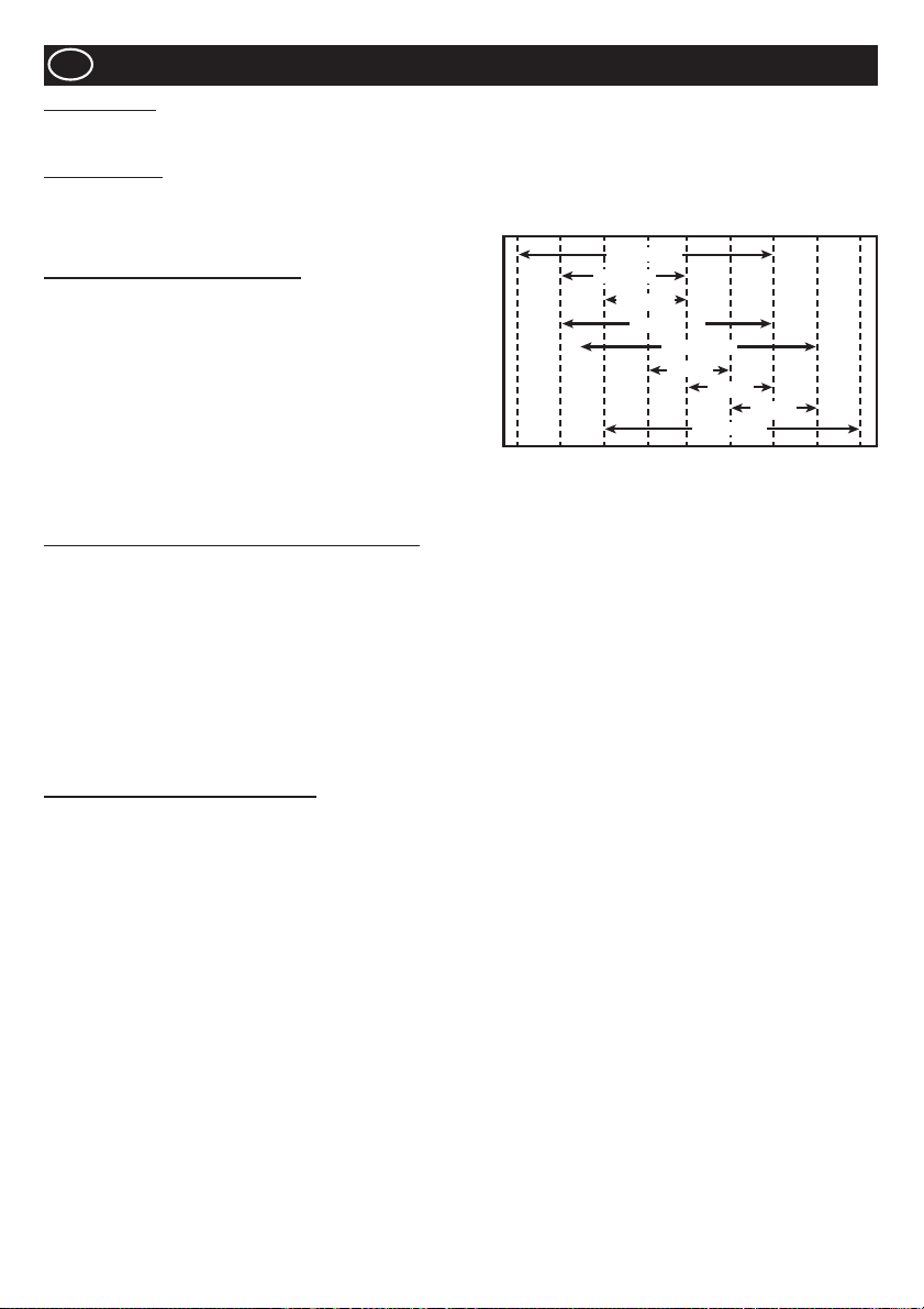
E
Mantenimiento
Aceite hidráulico
Ɣ Total EP32, Shell Tellus T37, MOBIL DTE15 or ESSO Unipower, XL46.
Aceite para motor
Seleccione la viscosidad del aceite para motor correspondiente en función de la temperatura ambiente y utilice el grá¿ co de grado de
viscosidad del servicio SAE que aparece a continuación.
Esta máquina viene de fábrica con SAE 15W-40.
Especi¿ caciones del aceite para motor
Utilice un aceite para motor que cumpla o supere las siguientes pautas
o clasi¿ caciones:
Categorías de servicio
Ɣ Categorías de servicio API CD o superior.
Ɣ Categorías de servicio ACEA E-3, E-4 y E-5
Ɣ Categoría de servicio JASO DH-1
De¿ niciones
Ɣ Clasificación API (American Petroleum Institute)
Ɣ Clasificación ACEA (Association des Constructeurs
Européens d’automobilies)
Ɣ JASO (Japanese Automobile Standards Organisation)
30°F
(22°C)
(-20°C)
-4°F
SAE 10W
14°F
(-10°C)
SAE 5W-30
SAE 20W
SAE 10W-30
32°F
(0°C)
SAE 15W-40
SAE 20
SAE 30
SAE 20W-50
50°F
68°F
(10°C)
(20°C)
SAE 40
86°F
(30°C)
104°F
(40°C)
122°F
(50°C)
Procedimiento de cambio del aceite para motor - Yanmar
1. Asegúrese de que el rodillo esté en una super¿ cie nivelada y la empuñadura de funcionamiento en la posición de almacenamiento.
Accione el freno de estacionamiento.
2. AÀ oje la tuerca de la parte inferior del tapón de llenado/drenaje de aceite. NOTA: NO quite el tapón en este momento.
3. Deslice la manguera desde el panel lateral.
4. Quite los 4 tornillos M8 con una llave inglesa de 13 mm. Retire el panel lateral.
5. Retire la manguera del chasis, quite el tapón y drene el aceite en un contenedor.
6. Vuelva a colocar el panel lateral utilizando una llave inglesa de 13 mm y vuelva a deslizar la manguera de llenado/drenaje en la
ranura del panel. Apriete la tuerca para asegurar el panel lateral pero manténgalo destapado.
7. Con la ayuda de un embudo, vierta el aceite en la manguera de relleno. Tenga cuidado al realizar esta operación para que no se
exceda la capacidad. Utilice una varilla en el lado izquierdo del motor para comprobar el nivel de aceite.
8. Vuelva a colocar el tapón de llenado/drenaje.
9. Compruebe que la máquina funciona correctamente.
Procedimiento para reemplazar la batería
1. Retire los 4 tornillos de la protección lateral mediante el uso de una llave de tubo de 13 mm y extraiga dicha protección. Guarde las
sujeciones.
2. Mediante una llave de tubo de 11 mm, retire el cable de tierra de la batería y, a continuación, quite el cable positivo de la batería.
3. Retire la abrazadera y el cojinete de la batería. Quite las dos tuercas y las dos arandelas con la ayuda de una llave inglesa de
13 mm.
4. Retire el terminal largo de la batería y la arandela utilizando una llave inglesa de 13 mm.
5. Quite los dos tornillos del regulador utilizando una llave de tubo de 10 mm.
6. Desmonte el soporte que se encuentra detrás del regulador utilizando una llave de tubo de 10 mm. Asegúrese de que no se ex
travíe el separador por detrás del soporte.
7. Mueva la correa de seguridad À exible de cables y saque los cables.
8. Extraiga la batería antigua y coloque la nueva.
9. Coloque de nuevo los cables en su sitio y asegure la posición de la batería con la correa de seguridad de cables.
10. Vuelva a colocar el soporte y el separador y apriételos a 12 Nm.
11. Vuelva a situar los dos tornillos en el regulador y apriételos a 12 Nm.
12. Vuelva a poner el terminal de la batería y la arandela, y apriételos a 28 Nm.
13. Coloque de nuevo la abrazadera y el cojinete utilizando una llave inglesa de 13 mm. Apriete la tuerca para garantizar que quedan
expuestos 8 mm de rosca.
14. Conecte el cable positivo a la batería y, a continuación, haga lo mismo con el cable de tierra.
15. Vuelva a colocar la protección lateral. Apriete los 4 tornillos de protección a 28 Nm.
54
Page 55
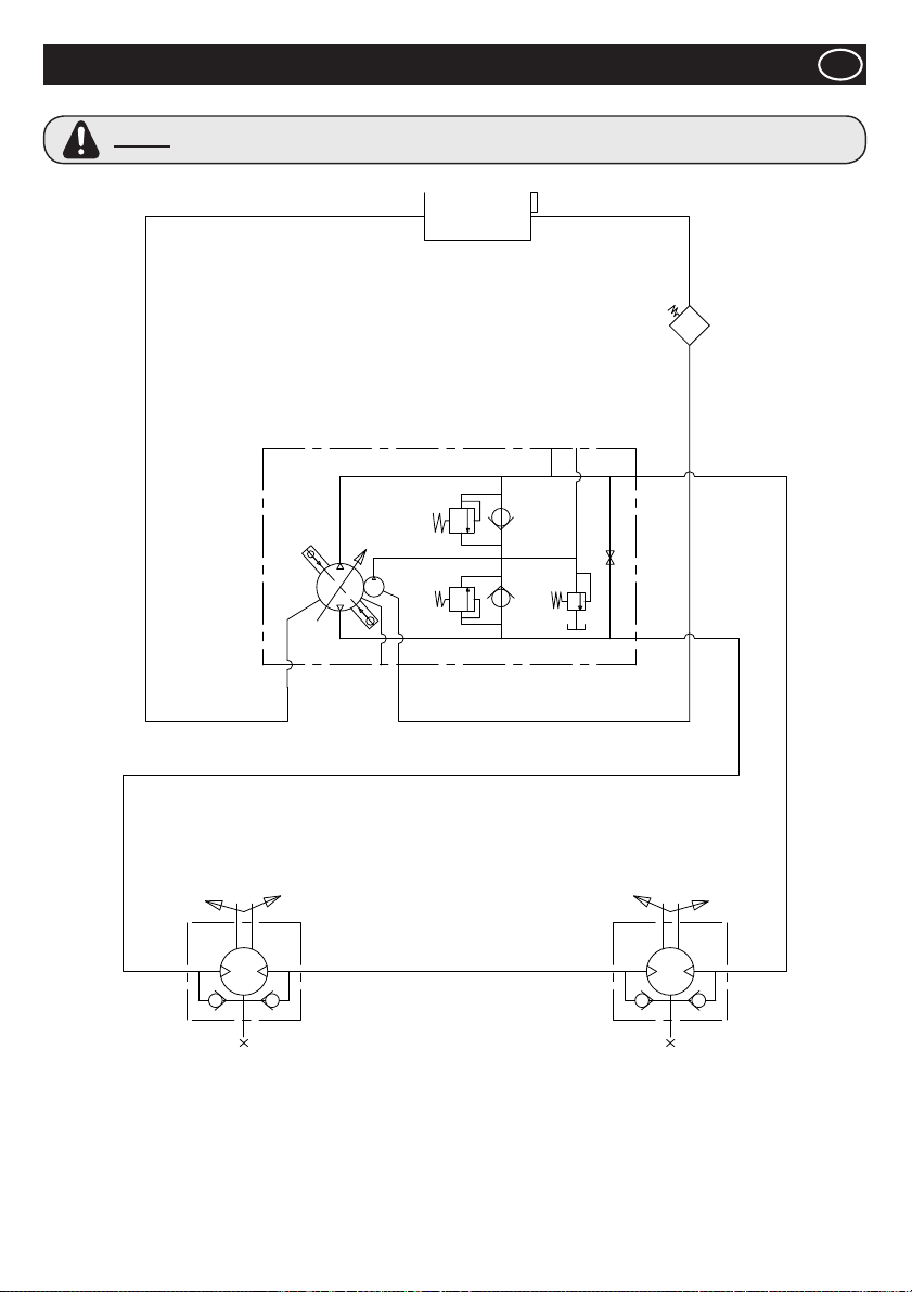
Circuito hidráulico
E
AVISO
En caso de efectuarse trabajos de reparación en el circuito hidráulico, será necesario desenroscar la tapa
del depósito para asegurarse de que el sistema no está presurizado.
55
Page 56
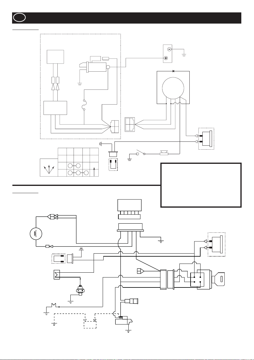
E
Yanmar L100N
Diagrama de cableado
Kubota EA330
12V - 15A
Dinamo
G/W G/W
CB104 CB104
CA104 CA104
G/W G/W
Regulador
CÓMO FUNCIONA EL INTERRUPTOR DE LLAVE
IG BAT ST NOTE
OFF
OFF12
1
2
Y
Motor de arranque
12 v CC 0,8 kW
W
JAS0
D601
20T
YAZAKI NO.
7323-2446
W
G
Y
AUTO
Cable de Conexión
a la Hora de Reloj
AV2 0
AV1 .25
AV1 .25
AV1 .25
AV2 0
Interruptor de llave
G
R
W
M8
Tornillo
R
YAZAKI NO.
7322-2446
RY
B
B
R
WG
WG
Interruptor de
presión del aceite Sirena
BR
Tierra
Diodo
IG
ST
(15)
(50)
Inventario
BAT
(30)
Batería
de tierra
(25)
Y
Y
Opción de
Reloj Hora
G = Verde IG = Ignición
W = Blanco BAT = Batería
Y = Amarillo ST = Arranque
R = Rojo BK = Negro
Regulador
BL = Azul SB = Azul Cielo
OR = Naranja BR = Marrón
Y
SBGBK
SB
R
Fan
Dynamo
Cable de Conexión
a la Hora de Reloj
BK/R
R
B
BK
SB
Zumbador
Interruptor
de Aceite
Bujía Incandescente
BR
Y
Batería
BR
BR
Y
Y
R
Y
Y
W
W
BK/R
R
BK/W
Y
G
R
Opción de
Reloj Hora
Interruptor de
Arranque
R
Fusible
Arranque
56
Page 57
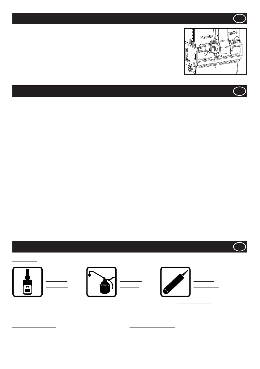
Almacenamiento Prolongado
1. En almacenaje prolongado, vaciar el combustible restante del depósito por cualquier
medio de succión desde el ori¿ cio de llenado ó desde el ¿ ltro de combustible una vez la tapa
haya sido retirada.
2. Limpiar el Filtro de Aire.
3. Limpiar de aceite y suciedad acumulada de todas las zonas de goma.
4. Limpiar la bandeja base y aplicar una ligera capa de aceite para prevenir su corrosión.
5. Cubrir la máquina y guardar en un lugar seco.
6. La Barra de Manipulación de la máquina puede ser retirada para su almacenaje. Tirar del
Obturador, y subir la barra. Comprobar que el Obturador mantiene segura dicha Barra de
Maniobra.
E
CERROJO
Garantia
La nueva apisonadora de plato Altrad Belle TDX 650A una garantía de un año (12 meses), para el comprador original, a partir de la
fecha original de compra.
La garantía de Altrad Belle le ampara contra defectos de diseño, materiales y mano de obra.
La garantía de Altrad Belle no cubre lo siguiente:
1. Daños causados por el abuso, mal uso, caída u otros daños similares causados por o como resultado del incumplimiento
de las instrucciones de ensamblaje, operación o mantenimiento por parte del usuario.
2. Las alteraciones, adiciones o reparaciones efectuadas por personas ajenas a Altrad Belle o a sus agentes reconocidos.
3. Los costos de transporte o embarque a y de Altrad Belle o sus agentes reconocidos, para la reparación o evaluación de una
máquina al amparo de una reclamación contra la garantía.
4. Los costos de materiales y mano de obra relacionados con la renovación, reparación o recambio de componentes por
desgaste normal.
Los siguientes componentes no están amparados por la garantía.
• Filtro de aire del motor
Altrad Belle y/o sus agentes reconocidos, directores, empleados o aseguradores no se responsabilizan de ningún daño consecuencial
u otros, pérdidas o gastos relacionados con o debidos a la inhabilidad de usar la máquina.
Reclamaciones contra la garantía
Todas las reclamaciones presentadas al amparo de la garantía deben dirigirse primero a Altrad Belle ya sea por teléfono, fax, correo
electrónico o por escrito.
Para las reclamaciones contra la garantía:
Altrad Belle Warranty Department,
Sheen, Nr. Buxton,
Derbyshire, SK17 0EU, England.
Información sobre las piezas de repuesto
E
E
LEYENDA
UTILICE
LOCTITE
Para obtener información sobre la disponibilidad de piezas de repuesto para la máquina, visite www.Belle247.com o póngase en
contacto con ALTRAD Belle:-
# - Opciones de color 1 ## - Opciones de color 2
N.º de pieza + S = Naranja (Ej. 981/05100S) N.º de pieza + GR = Gris (Ej. 981/03200GR)
N.º de pieza + G = Verde N.º de pieza + GR2 = Gris Cuarzo
N.º de pieza + B1 = Azul N.º de pieza + BL = Negro
N.º de pieza + R1 = Rojo N.º de pieza + W = Blanco
N.º de pieza + Y = Amarillo
N.º de pieza + Y2 = Amarillo
UTILICE
ACEITE
ILICONE
S
UTILICE
SILICONA
57
Page 58
Como utilizar este manual
Esta manual foi redigido para ajudar a operar e assistir em segurança o Cilindro Vibratório de Condução Pedestre Belle da Série TDX.
Este manual é destinado aos distribuidores e operadores dos Modelos TDX 650A.
Conteúdo
A secção ‘Ambiente’ explica quais as peças substituídas e acessórios que se devem enviar para reciclagem.
A secção ‘Descrição da Máquina’ ajuda a familiarizar-se com o desenho da máquina e os controlos.
As secções ‘Segurança Geral’ e ‘Saúde e Segurança’ explicam como utilizar a máquina em segurança tanto para o operador como
para o público em geral.
A secção ‘Procedimentos de Arranque e Paragem’ ensina a arrancar e parar a máquina correctamente.
O guia ‘Resolução de Problemas’ ajuda no diagnóstico de pequenos problemas com a máquina.
A secção ‘Assistência’ dá orientação sobre as rotinas de manutenção e reparação da máquina.
A secção ‘Listagem e Diagramas das Peças’ mostra e descreve em detalhe os componentes e referências das peças principais para
eventual substituição.
Directrizes com símbolos.
Os textos deste manual aos quais se deve prestar uma atenção especial estão assinalados do seguinte modo:
CUIDADO
O produto pode ser de risco. A máquina pode sofrer danos e/ou o operador ferimentos se os
procedimentos não forem conduzidos correctamente.
AVISO
A vida do operador pode estar em risco.
Aviso
AVISO
SABER como utilizar em segurança os controlos da máquina e quais os procedimentos para uma manutenção isenta de riscos.(Nota:
Certi¿ que-se que sabe desligar a máquina antes de a pôr a trabalhar, para o caso de uma emergência.)
Utilizar ou vestir SEMPRE os equipamentos de segurança apropriados necessários à sua protecção pessoal.
Se tiver QUALQUER PERGUNTA acerca da utilização ou manutenção em segurança desta máquina, CONSULTE O SEU
FORNECEDOR OU CONTACTE UMA DAS EMPRESAS DA Altrad Belle ABAIXO INDICADAS:
Altrad Belle (England, Tel: +44(0)1298 84606)
Antes de operar ou de levar a cargo qualquer trabalho de manutenção, DEVERÁ LER e ESTUDAR
este manual.
Indice
Como utilizar este manual ........................................................................................................................................................................58
Aviso .........................................................................................................................................................................................................58
Dados Téchnicos ......................................................................................................................................................................................59
Etiquetas........................................................................................................................................................................................... 60 - 61
Descrição da máquina..............................................................................................................................................................................62
Segurança geral .......................................................................................................................................................................................62
Saúde e Segurança..................................................................................................................................................................................63
Veri¿ cações pré-arranque ........................................................................................................................................................................63
Ambiente ..................................................................................................................................................................................................63
Procedimentos Arranque/Paragem ..........................................................................................................................................................64
Operar o TDX ...........................................................................................................................................................................................65
Assistência Técnica .......................................................................................................................................................................... 65 - 67
Circuito Hydráulico ...................................................................................................................................................................................68
Diagrama de Fiação .................................................................................................................................................................................69
Armazenamento de longe duração ..........................................................................................................................................................70
Garantia ....................................................................................................................................................................................................70
Informações de peças sobressalentes .....................................................................................................................................................70
Declaração de Conformidade ...................................................................................................................................................................2
58
Page 59
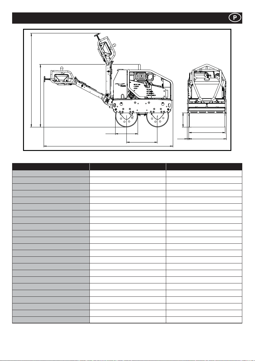
Características Técnicas
J
B
G
D
A
Modelo TDX 650A Yanmar L100N TDX 650A Kubota EA330
Peso* - Kg 675 684
A - Comprimento Total - mm 2318 2318
B - Altura Total - mm 1137 1137
C - Distância entre-eixos - mm 560 560
D - Diâmetro dos rolos - mm 402 402
E - Largura dos rolos - mm 650 650
F - Largura Total - mm 703 703
G - Distância ao passeio - mm 258 258
H - Inclinação lateral - mm 26.5 26.5
J - Altura em Sala - mm 1678 1678
Velocidade de tabalho Marcha à Frente - m/m (km/h)
Velocidade de tabalho Marcha atrás - m/m (km/h)
Frequência de vibração - v.p.m 3300 3300
Força centrífuga - kN 16 16
Capacidade do depósito de água - Ltr 65 65
Capacidade do depósito de óleo - Ltr 16 16
Motor YANMAR L100N KUBOTA EA330
Tipo 4-Tempos Refrigerador de Ar 4-Tempos Refrigerador de água
Combustível Diesel Diesel
Depósito de combustível - Ltr 5.4 4.8
Potência Avaliado - Hp (kW) 9 (6.6) 5.9 (4.4)
Potência máxima - Hp (kW) 10 (7.4) 6.9 (5.2)
Arranque
* O peso indicado corresponde ao peso com o depósito de água vazio. Água no depósito = 65 litros = 65 Kg
Elétrica (Recoil opção de backup começar) Elétrica
0 - 70 (0 - 4.2) 0 - 70 (0 - 4.2)
0 - 38 (0 - 2.3) 0 - 38 (0 - 2.3)
C
H
E
F
59
Page 60
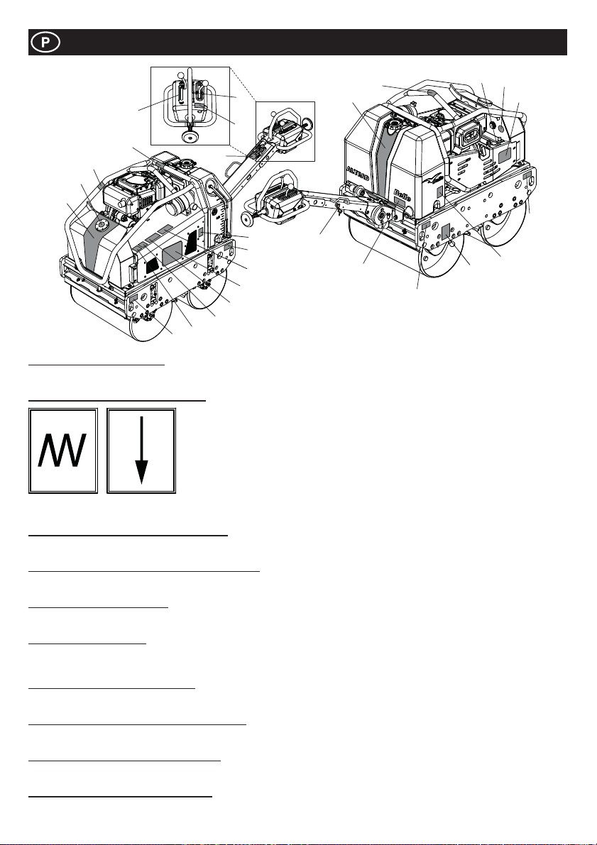
Etiquetas
7
5
17
10
18
1
22
9
Itens 1 a 4 – Etiquetas da marca
Etiquetagem da marca para identi¿ car o rolo compressor TDX.
Item 5 – Etiqueta da alavanca de vibração
6
21
8
9
25
3
24
23
19
2
20
14
9
Nota:- A ilustração mostra o modelo L100N Yanmar.
13
12
4
9
16
15
Vibração
activada
Item 6 – Etiqueta Cuidado!/Consultar o manual
CUIDADO! Consulte o Manual do Operador antes de utilizar o equipamento.
Item 7 – Etiqueta da alavanca de marcha à frente/atrás
Alavanca para mudar a direcção de marcha do equipamento. F = Marcha à frente, R = Marcha-atrás, Ɣ = Ponto-morto.
Item 8 – Etiqueta de manutenção
Indica que a capota pode ser removida para intervenções de manutenção no interior.
Item 9 – Etiqueta de ¿ xação
Identi¿ ca as áreas que podem ser utilizadas para ¿ xar o equipamento a um guincho para elevação ou as áreas destinadas à ¿ xação
por correias durante o transporte.
Item 10 – Etiqueta de superfície quente
CUIDADO! Tenha especial cuidado com as superfícies quentes em redor das áreas do depósito hidráulico e da zona de escape.
Item 11 – Etiqueta de enchimento do óleo do motor
Indica a localização de enchimento para repor o nível de óleo do motor e a localização de veri¿ cação do nível de óleo.
Item 12 – Etiqueta de nível do óleo hidráulico
Indica a posição do medidor de óleo hidráulico, o qual apresenta o nível de óleo hidráulico no depósito.
Item 13 – Etiqueta de tipo de óleo do motor
Explica o tipo de óleo que deve ser utilizado no motor.
Vibração
desactivada
60
Page 61
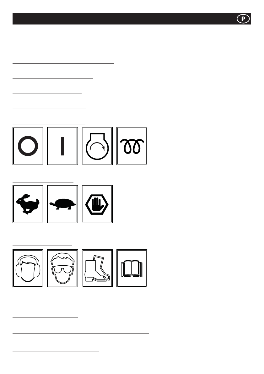
Etiquetas
Item 14 – Etiqueta de escoamento de água
Se a temperatura ambiente prevista estiver abaixo do limiar de congelação, é necessário esvaziar o depósito de água utilizando o
tampão de escoamento.
Item 15 – Etiqueta de travão de segurança
Apresenta a posição do travão de segurança. É necessário aplicar o travão de segurança quando o equipamento não se encontra em utilização.
Item 16 – Etiqueta de torneiras das barras de injecção
Indica a posição das torneiras das barras de injecção e as torneiras correspondentes a cada uma das barras de injecção.
Item 17 – Etiqueta de utilização de gasóleo
Deve APENAS ser utilizado gasóleo no motor!
Item 18 – Etiqueta de óleo hidráulico
Localização do bujão de enchimento do depósito de óleo do sistema hidráulico.
Item 19 – Etiqueta de olhal de elevação
Indica o olhal de elevação para utilização com uma linga ou guincho mecânico.
Item 20 – Etiqueta da chave de ignição
DESLIGADO
Item 21 – Etiqueta de acelerador
Posição de
RPM máx.
Item 22 - Etiqueta de segurança
Usar
equipamento
de protecção
auditiva
Item 23 - Etiqueta de nível de ruído
Nível de ruído auditivo garantido do equipamento, em dB(A).
Item 24 – Autocolante de aviso de gases de escape (Peça N.º 800-99520)
Estes motores emitem monóxido de carbono. Utilizar apenas em áreas com boa ventilação.
Item 25 – Etiqueta de perigo de esmagamento
CUIDADO! Cuidado com os componentes mecânicos se guarda é removido.
LIGADO ARRANQUE
Posição
ralenti
Posição de
paragem de
emergência
Usar
equipamento
de protecção
ocular
Usar calçado
de protecção
CALOR
(KUBOTA)
Consulte o
Manual do
Operador
61
Page 62
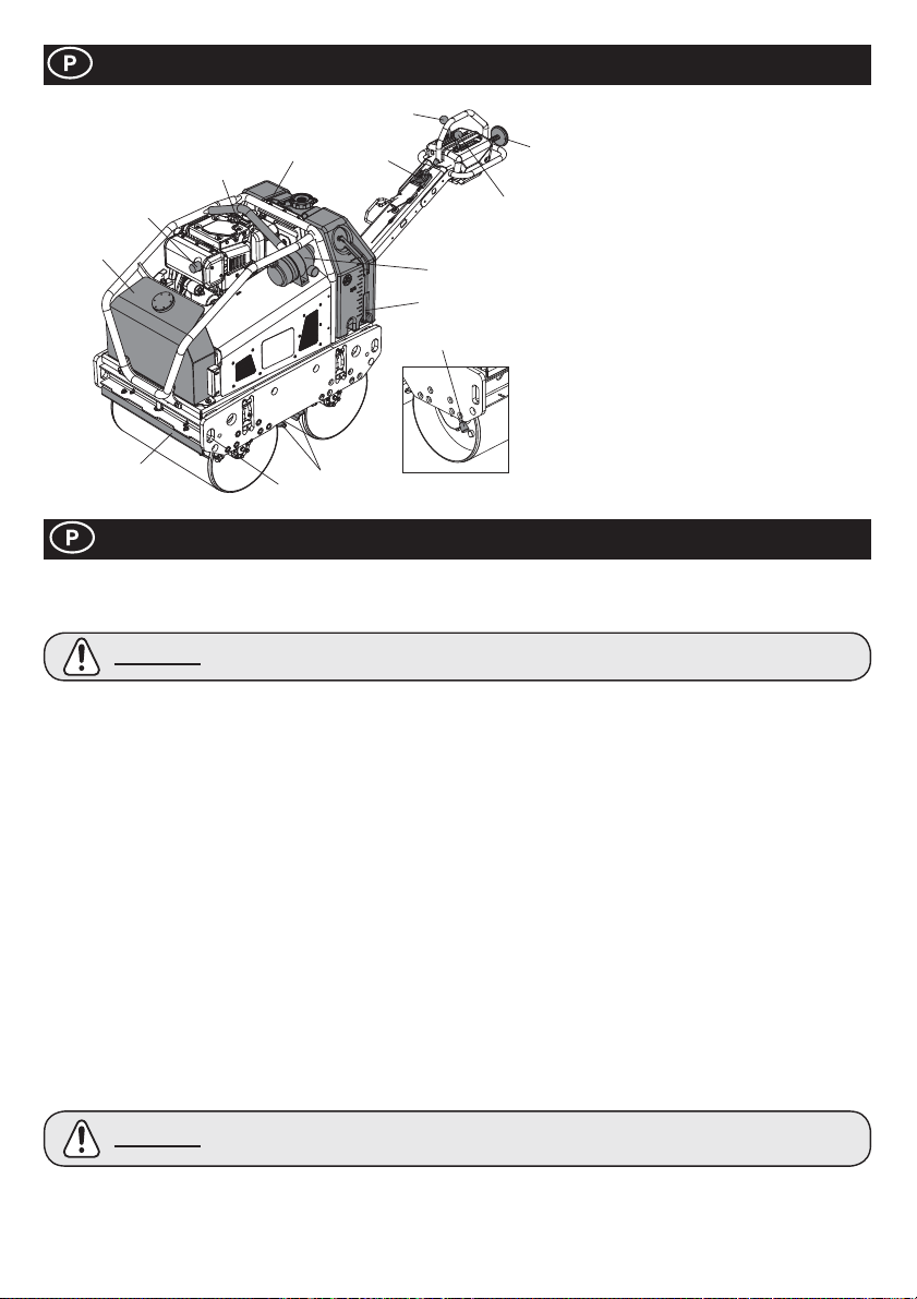
Descrição da máquina
5
1. Depósito de Óleo Hidráulico.
2
12
1
10
4
11
8
3
9
13
10
7
2. Olhal de elevação.
6
3. Filtro de Ar.
4. Depósito de água.
5. Comando de Marcha á frente / atrás.
6. Comando de Vibração.
7. Comando de paragem de emergência.
8. Acelerador.
9. Indicador de nível da água.
10. Barras de raspagem.
11. Pontos de ¿ xação.
12. Escape.
13. Travão de estacionamento.
Nota:- A ilustração mostra o modelo L100N
Yanmar.
Segurança Geral
Para sua protecção e segurança das pessoas que o rodeiem, por favor leia com cuidado e assegure-se que percebeu as seguintes
informações de segurança. È da responsabilidade do operador certi¿ car-se que percebeu como é que deve trabalhar com este
equipamento de forma segura. Se está indeciso sobre a correcta e segura utilização do equipamento deve consultar o seu fornecedor
ou qualquer das empresas do Grupo Belle.
CUIDADO
Ɣ Esta máquina só deve ser usada para o ¿ m para que foi concebida.
Ɣ
Esta máquina só deve ser utilizada por pessoal correctamente treinado para esse ¿ m.
O proprietário desta máquina deverá cumprir e treinar o respectivo operador para que também cumpra os Regulamentos de
Ɣ
Protecçăo Laboral em vigor no respectivo país.
Ɣ
Utilizar um equipamento de elevaçăo adequado para içar a máquina.
Ɣ
Esta máquina deverá ser operada em solo onde esteja garantida a estabilidade. Quando em trabalhos perto de valas escavadas,
usar a máquina correctamente de modo a evitar que esta resvale ou caia.
Ɣ
Se a superfície a ser compactada é inclinada dever-se-á ter grande cuidado no controlo do sentido do movimento da máquina.
Quando trabalhar num declive deverá fazĊ-lo a subir ou a descer e nunca perpendicularmente ao sentido da inclinaçăo.
Ɣ
Isolar a área de trabalho e manter o público e pessoal năo autorizado a uma distância de segurança.
Equipamento de Protecçăo Pessoal (EPP) deverá ser usado pelo operador em todas as situaçĘes aconselháveis. (Ver Saúde
Ɣ
& Segurança)
Ɣ
Certi¿ que-se que sabe desligar a máquina antes de a pôr a trabalhar, para o caso de uma emergĊncia.
Ɣ
Desligar sempre o motor (OFF) antes de qualquer trabalho de manutençăo.
Durante a utilizaçăo o motor aquece bastante. Deixar o motor arrefecer antes de lhe tocar.
Ɣ
Ɣ
Nunca deixar a máquina a trabalhar e sem vigilância.
Năo retirar ou alterar qualquer das protecçĘes da máquina. Existem para sua protecçăo. Veri¿ car com frequĊncia a condiçăo e
Ɣ
segurança das protecçĘes. Se alguma estiver dani¿ cada ou tiver desaparecido, NĂO UTILIZAR A MÁQUINA até que a protecçăo
tenha sido substituída ou reparada.
Ɣ
Năo operar a máquina se estiver doente, cansado ou debaixo da inÀ uĊncia de álcool ou drogas.
Esta máquina foi concebida para eliminar os possíveis riscos da sua utilizaçăo. Contudo, EXISTEM alguns riscos residuais que
Ɣ
năo săo facilmente reconhecíveis e poderăo eventualmente causar lesĘes ou danos patrimoniais e mesmo a morte. Se algum
destes riscos imprevisíveis e irreconhecíveis se tornar evidente, a máquina deverá ser parada imediatamente e o operador ou
o seu encarregado deverá tomar as medidas apropriadas para eliminar tais riscos. É necessário informar o fabricante de tal
acontecimento para que futuramente seja tomado em consideraçăo.
Segurança do Combustível
CUIDADO
Antes de abastecer, desligar o motor e deixar arrefecer.
Ɣ
Ɣ
Quando abastecer, NÃO FUMAR ou permitir chama nua nas redondezas.
Ɣ
Quando abastecer, usar um funil apropriado e evitar derramar sobre o motor.
Se derramar combustível tapar imediatamente com areia. Se entornar no vestuário, mudar de roupa.
Ɣ
Guardar o combustível em reservatório próprio e aprovado, longe de fonte de aquecimento ou de ignição.
Manutenção incorrecta pode ser perigosa. Leia e Compreenda esta secção antes de proceder a
qualquer trabalho de manutenção ou reparação.
O combustível é inÀ amável. Pode causar lesões e danos patrimoniais. Desligar o motor, extinguir qualquer
chama nua e não fumar enquanto encher o depósito de combustível. Limpar sempre qualquer derrame
de combustível.
62
Page 63
Saúde e Segurança
Vibração
Quando a máquina está a trabalhar, alguma vibração transmite-se pelo guiador para as mãos do operador. O Cilindro Vibratório
de Condução Pedestre Belle da Série TDX 650A foi especi¿ camente concebido para reduzir os níveis de vibração Mão/Braço.
Consultar as especi¿ cações e os dados técnicos para níveis de vibração e tempos de utilização (tempo de exposição máximo diário
recomendado). NÃO EXCEDER o tempo máximo de utilização.
EPP (Equipamento de Protecção Pessoal)
Quando trabalhar com esta máquina deverá ser utilizado EPP adequado, ex. Óculos Protectores, Luvas, Protectores dos Ouvidos,
Máscara contra Pó e Calçado de Ponteira de Aço.
Vestir roupa adequada para o trabalho que vai fazer. Se usar cabelo comprido, prenda o cabelo e/ou tire as jóias que eventualmente
use devido a poderem ser apanhadas pelas peças rotativas da máquina.
Pó
O processo de compactação pode produzir pó que inalado é perigoso para a saúde. Utilizar sempre uma mascara adequada contra o
tipo de pó que está a ser produzido.
Combustível
Não inalar vapores do combustível ou ingerir combustível e evitar o contacto com a pele. Lavar imediatamente salpicos de
combustível. Se o combustível atingir os olhos, irrigá-los com água abundante e consultar um medico imediatamente.
Gases do Escape
Não trabalhar com a máquina em espaços fechados ou em áreas de dimensões reduzidas. Certi¿ que-se que a área de trabalho está
devidamente ventilada.
AVISO
Os gases do escape produzidos por esta máquina são altamente tóxicos e podem causar a morte.
Veri¿ cações Pré-arranque
Inspecções Pré-arranque
As seguintes Veri¿ cações Pré-arranque devem ser executadas antes do começo do turno de trabalho ou depois de quatro horas de
utilização, dependendo da situação. Consultar a secção de assistência para informação detalhada. Se descobrir alguma avaria, a
máquina não deverá ser utilizada até que essa avaria seja reparada.
1. Inspeccione minuciosamente a máquina procurando sinais de estragos.
2. Detectar se as mangueiras, a abertura do depósito de combustível, os bujões de drenagem e quaisquer outras áreas não têm
sinais de perdas ou fugas. Reparar qualquer fuga antes de operar.
3. Veri¿ car o nível de óleo do motor e atestar se necessário.
3a. Colocar a máquina numa superfície nivelada para poder veri¿ car apropriadamente o nível do óleo.
3b. Retirar o tampão do Óleo e observar se o óleo atinge a borda do depósito. Usar óleo de motor adequado e com grau de
viscosidade apropriado. (Consulte o grá¿ co do grau de viscosidade de serviço SAE na secção Serviço)
4. Veri¿ car o nível de combustível do motor e atestar se necessário. Usar combustível limpo. A utilização de combustível
contaminado poderá dani¿ car o respectivo sistema.
5. Averiguar se o ¿ ltro de ar está limpo.
Acumulação excessiva de sujidade/pó no elemento do ¿ ltro pode causar inexactidão no trabalho do motor. Limpar o elemento
do ¿ ltro de ar quando estiver contaminado. (Ver a secção de Manutenção)
6. Examinar as funções dos Controlos do Operador
Con¿ rmar se os Comandos de Direcção, Vibração, Acelerador, Travão de Estacionamento e o Dispositivo de Paragem de
Emergência se movem suavemente.
7. Veri¿ que o nível do líquido de arrefecimento do motor. Top até o nível ‘encher’, se necessário - KUBOTA SOMENTE!
Ambiente
Remoção segura
Instruções para a protecção do ambiente. A máquina
contém materiais de valor. Levar as peças e
acessórios descartados para os locais de reciclagem.
Componentes Material
Pega Aço
Quadro Principal Aço
Depósito de óleo Hidráulico Aço
Depósito de água Polietileno
Cobertura Polietileno
Bomba Hidráulico Aço e Alumínio
Motor Hidráulico Aço
Motor Aço e Alumínio
Peças Variadas Aço, Alumínio e Borracha
63
Page 64
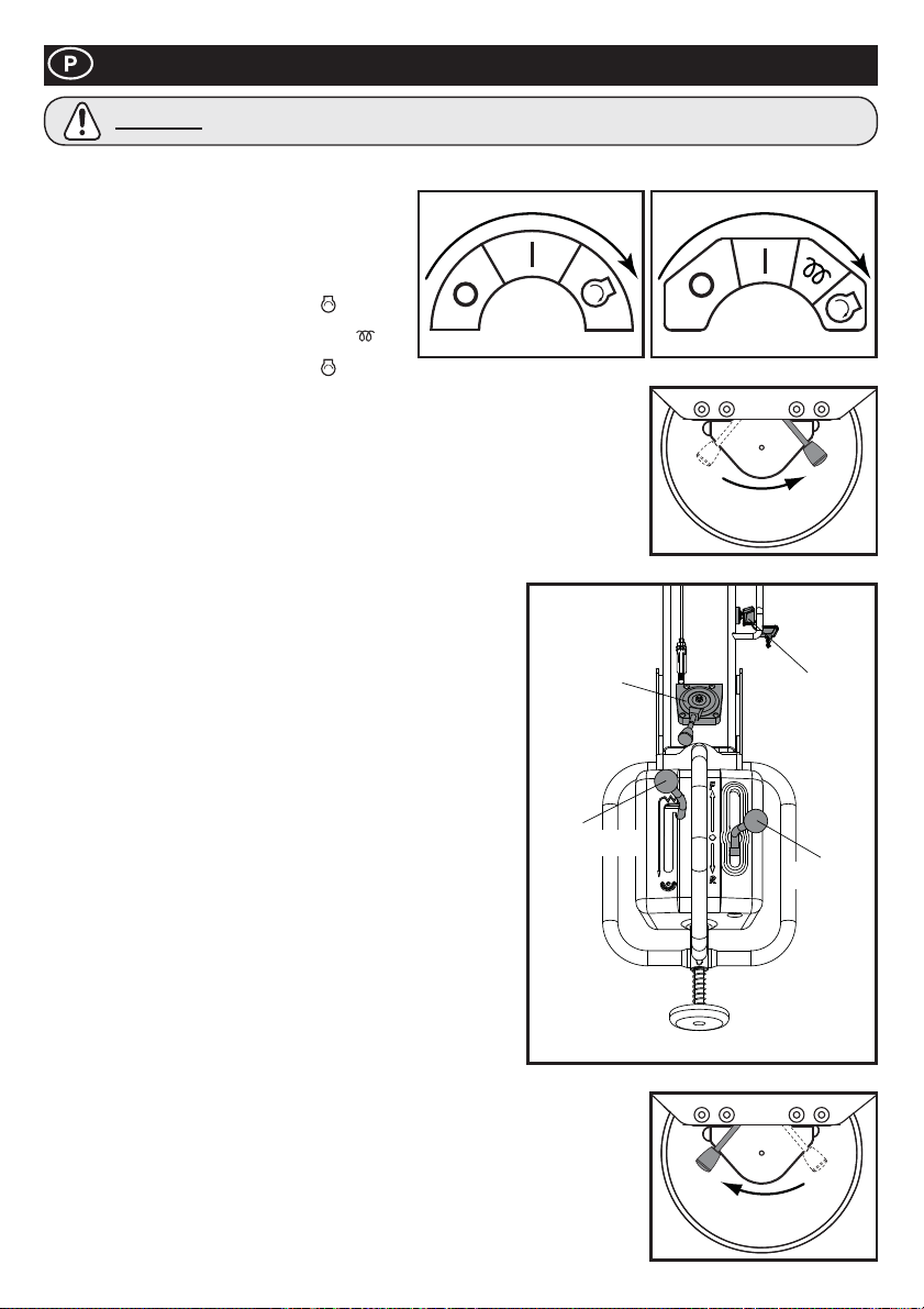
Procedimentos Arranque/Paragem
CUIDADO
Antes de arrancar com o motor, con¿ rmar que o Comando do Sentido de Marcha está no Ponto Morto, o Comando de Vibração está
desligado (OFF) e o Travão de Estacionamento está accionado (ON).
1. Abra a torneira de combustível no motor.
2. Mova a alavanca de aceleração no manípulo de
operação para a posição de aceleração máxima (lebre).
Arranque do motor – Arranque eléctrico
3ai. YANMAR - Rode a chave da ignição na alavanca de
aceleração para a posição de arranque
mantenha-a nessa posição até o motor arrancar.
3aii. KUBOTA - De legal, espera posição de calor
10 segundos. Rode a chave da ignição na alavanca de
aceleração para a posição de arranque
NÃO efectue acelerações durante longos períodos de tempo. (Máximo: 10 segundos).
3b. Após o arranque do motor, certi¿ que-se de que a chave de ignição é colocada na posição
LIGADO (I) durante o funcionamento. (Colocar a chave de ignição na posição DESLIGADO
(0) não permitiria que o gerador carregasse a bateria.)
Arranque do motor – Arranque manual
4a. Segure com ¿ rmeza no manípulo de accionamento do motor de arranque.
4b. Puxe o manípulo lentamente até sentir forte resistência.
4c. Regresse à posição inicial do manípulo.
4d. Empurre a alavanca de descompressão e solte-a. A alavanca de descompressão regressará
automaticamente à posição de origem quando o motor arrancar.
4e. Segure com ¿ rmeza no manípulo de accionamento do motor de arranque.
4f. Puxe o manípulo totalmente para fora com um movimento contínuo forte.
Se necessário, utilize as duas mãos.
4g. Coloque lentamente o manípulo de arranque na posição inicial.
4h. Se o motor não arrancar, repita o procedimento descrito em 4b.
5. Mova a alavanca de aceleração para a posição LOW e deixe o motor
funcionar ao ralenti durante alguns minutos, para aquecer.
Após o aquecimento do motor, o equipamento está pronto para utilização.
6.
7. Mova rapidamente a alavanca de aceleração para a posição de
velocidade máxima, “H”, de modo a impedir a ocorrência de danos na
embraiagem. A posição “Aceleração máxima” deste equipamento foi
prede¿ nida em fábrica para obter o melhor desempenho do equipamento.
NÃO altere esta de¿ nição, uma vez que isso poderia provocar o
desgaste prematuro ou danos, da mesma forma que anularia
automaticamente a garantia do equipamento e do motor.
8. Mova a alavanca do travão de segurança para a direita, para
desengatá-lo.
NOTA: Se o desengate do travão de segurança for negligenciado antes de
engatar a marcha no equipamento, ocorrerão danos graves no mecanismo
de travagem e na transmissão.
9. Controlos do operador
9a. Alavanca de aceleração
Mantenha sempre a alavanca de aceleração na posição de aceleração
máxima durante o funcionamento. NÃO tente alterar a velocidade de
deslocação modi¿ cando o sistema de revolução do motor.
9b. Alavanca da transmissão
Mova a alavanca da transmissão para a frente, para accionar a marcha
do equipamento. Para marcha-atrás, mova a alavanca para trás.
9c. Alavanca de vibração
Ao colocar a alavanca de vibração na posição LIGADO, o mecanismo
de vibração será activado e será produzida vibração.
10. Parar o motor
11. Como preparação para desligar o motor, mova a alavanca de aceleração para a posição
de BAIXA aceleração.
12. Deixe o motor funcionar ao ralenti durante 1 a 3 minutos.
13. Coloque a alavanca de aceleração na posição de PARAGEM, para parar o motor. Em
seguida, coloque a chave da ignição na posição “DESLIGADO”. Será ouvido um alerta
sonoro se a chave da ignição for colocada em LIGADO enquanto o motor se encontrar a
ser parado.
14. Feche a torneira de combustível
15. Aplique o travão de segurança, movendo a alavanca do travão de segurança para a
esquerda
NÃO TIRAR as mãos da Manivela durante os procedimentos de Arranque.
YANMAR KUBOTA
e
por
e mantenha-a nessa posição até o motor arrancar.
ALAVANCA
DE
ACELERAÇÃO
ALAVANCA DE
VIBRAÇÃO
DESENGATAR
ALAVANCA
ENGATAR
CHAVE
DA
IGNIÇÃO
UNIDADE
64
Page 65

Operação com os Cilindros TDX
Ɣ Depois de ter feito devidamente a inspecção “ pré arranque” pode ligar o motor
Os cilindros de condução pedestre da série TDX da Altrad Belle estão equipados com uma embraiagem centrífuga; isto
permite que o motor trabalhe em vazio sem activar a bomba hidráulica.
Quando a velocidade do motor aumenta a embraiagem é activada e o motor acciona a Bomba Hidráulica que envia a potência
Ɣ
para os rolos e para o mecanismo de vibração. Para evitar qualquer avaria na embraiagem centrífuga deve-se mover rapidamente
o acelerador da posição baixa L, para a posição alta H. Para se efectuar uma operação correcta a velocidade do motor deve ser
mantida no máximo durante o trabalho de compactação
Ɣ
Evitar trabalhar em superfícies já compactadas, duras ou demasiado moles. De outra forma os rolamentos e demais componentes
mecânicos poder-se-ão estragar e a vida da máquina ser signi¿ cativamente encurtada.
Ɣ
Quando estiver a trabalhar numa superfície em declive, tenha especial cuidado durante a operação do equipamento para garantir
que o rolo compressor não desliza no sentido descendente. Efectue sempre a operação do equipamento em subida ou descida.
Nunca trabalhe transversalmente à subida/descida. Se o equipamento estiver estacionado num declive, aplique sempre o travão
de segurança.
Quando a máquina recua tome cuidado para não ¿ car parado atrás do Guiador. Caminhar sempre à frente do referido Guiador
Ɣ
e virado para o mesmo
Içar
Ɣ
Sempre que for necessário utilizar equipamento de elevação para posicionar o TDX 650A, certi¿ que-se de que o equipamento
de elevação tem um limite de carga adequado ao peso do equipamento (consulte a tabela de especi¿ cações técnicas). Utilize
APENAS correntes ou lingas adequadas nos pontos de elevação fornecidos no centro do equipamento (olhal de elevação) ou em
cada canto do equipamento (pontos de ¿ xação).
TRANSPORTE
Ɣ
Transporte num veículo.
Assegure-se que o braço está trancado e use rampas adequadas com su¿ ciente largura, comprimento e resistência tanto para
carregar como para descarregar a máquina.
Aplique o freio de estacionamento, e amarrar a máquina com firmeza para o veículo durante o transporte.
Ɣ
Assistência Técnica
Manutenção
Os cilindros de condução pedestre da Altrad Belle TDX 650A estão concebidos para proporcionar muitos anos de trabalho livres
de problemas. Contudo, para que assim aconteça, é essencial que a manutenção regular indicada nesta secção seja efectuada.
Recomenda-se que as principais acções de manutenção e reparação sejam efectuadas pelos revendedores autorizados da Altrad
Belle. Devem-se usar sempre peças de substituição genuínas Altrad Belle, pois o uso de peças não autorizadas determina o
cancelamento automático da garantia.
Antes de efectuar qualquer intervenção de manutenção no equipamento, desligue o motor e remova a chave da ignição.
Tenha sempre a máquina nivelada de forma a poder fazer uma leitura correcta dos níveis dos À uídos. Utilize só os óleos
recomendados (consulte a página 67).
Assistência ao Motor
Na assistência ao motor devem ser respeitadas as especi¿ cações do respectivo fabricante.
Recorrer ao manual de manutenção e operação.
Nota: Quando re-montar a Cobertura para Manutenção é necessário certi¿ car-se que todos os Parafusos ¿ cam bem apertados.
Manutenção: Cada 8 horas ou diariamente
1. Veri¿ car se há pernos ou porcas desapertados e apertar, se necessário.
2. Veri¿ car o estado do elemento do ¿ ltro de ar, limpá-lo e lubri¿ cá-lo de acordo com as recomendações do fabricante do motor. Se
as condições de operação forem invulgarmente severas e poeirentas dever-se-á limpar o elemento com mais frequência.
3. Veri¿ que o nível de óleo do motor antes da operação.
Manutenção: Após as primeiras 50 horas e, posteriormente, a cada 200 horas
1. Mude o óleo do motor - ver procedimento na página 67.
65
Page 66

Assistência Técnica
Manutenção: Cada 50 horas ou semanalmente
1. Veri¿ car a tensão da Correia de Transmissão
1a. Desapertar os quatro pernos que ¿ xam o Suporte da
Bomba e rodar o Perno de Regulação até obter uma
tensão adequada. A correia deverá quando premida no
centro entre a embraiagem. Centrífuga e o tambor ter
uma folga de 5mm.
1b. Apertar os quatro pernos que ¿ xam o Suporte da
Bomba.
2. Regular a distância do Raspador
2a. Desmontar o Raspador e limpá-lo de qualquer sujidade,
ama e asfalto.
2b. Montar o Raspador no respectivo Suporte e ¿ xá-lo a
uma distância adequada do rolo.
3. Depósito de Água
3a. Esvazie o depósito por completo e limpe o interior
com uma mangueira
4. Bocal do Pulverizador
4a. Retirar a Cobertura do bocal e limpar o interior do
Bocal do Pulverizador.
5. Peças Rotativas
5a. Lubri¿ car o terminal dos Cabos de
Transmissão/Vibração.
5b. Aplique novamente massa lubri¿ cante nos pontos
respectivos do manípulo de operação.
5c. Untar o eixo vibrador
Manutenção: Cada 100 horas
1. Mecanismo de Embraiagem da Vibração
1a. Averiguar se o Mecanismo de Embraiagem da Vibração trabalha correctamente.
1b. Lubri¿ car as peças rotativas.
1c. Veri¿ car as condições da correia em V. Se esta estiver gasta ou golpeada, substituir.
Manutenção: Cada 500 horas
1. Substituir o Elemento do Filtro do Óleo Hidráulico cada 500 horas de operação.
Usar elementos do Filtro Originais.
Manutenção: Cada 800 horas
1. Mudar o Óleo Hidráulico. Drenar o depósito antes de encher com novo Óleo Hidráulico.
Para ventilar o sistema hidráulico, tirar o Tampão e deixar o depósito aberto, pôr o motor a trabalhar a velocidade máxima mas
sem operar tanto o Comando do Sentido de Marcha como o Comando de Vibração durante 10 minutos. Colocar o Tampão do
Depósito.
Regulação Do Ponto Morto Do Comando Do Sentido De Marcha
O Ponto Morto do Comando do Sentido de Marcha pode-se desregular devido à vibração ou ao desgaste dos cabos. Para regular a
posição de Ponto Morto, seguir as instruções abaixo indicadas:
1. Colocar a máquina numa superfície nivelada.
2. Certi¿ car-se que o motor está desligado “OFF”.
3. Retirar a Porca que ¿ xa o Terminal do Cabo de Transmissão ao Comando do Sentido de Marcha.
Não tentar pegar o motor enquanto esta porca não estiver colocada. A máquina poder-se-á mover repentina
AVISO
4. Soltar o Fecho da Porca no Terminal.
5. Rodar o Terminal para a esquerda ou direita dependendo da posição para a qual o ponto
morto mudou.
6. Ajustar o Terminal com o Cabo da Transmissão e prender com a porca.
7. Arrancar o motor e aumentar a rotação do motor até ao máximo. Veri¿ car se o ponto morto
está correctamente ajustado.
8. Se não estiver, parar o motor, retirar a porca e repetir os procedimentos de 5 a 7 até a
regulação do ponto morto ¿ car perfeita.
9. Quando o ponto morto estiver correctamente regulado, aplicar Loctite na Porca que ¿ xa o
Terminal e apertá-la. Depois, apertar o Fecho da Porca no terminal.
e anormalmente sem a capacidade de ser controlada pelo Comando do Sentido de Marcha e poderá causar
danos graves ou prejuízos patrimoniais.
CORREIA DA TRANSMISSÃO
REGULADOR
DA CORREIA
BOCAL DO
PULVERIZADOR
PONTOS DE
LUBRIFICAÇÃO
DO SUPORTE
PARAFUSO
RASPADOR
DEPÓSITO
EMBRAIAGEM DA
VIBRAÇÃO
COMPONENTE
DEL FILTRO
PORCA DE TRAVAMENTO
TAMPÃO
CORREA-V
TAPÓN
DE
VACIADO
66
Page 67
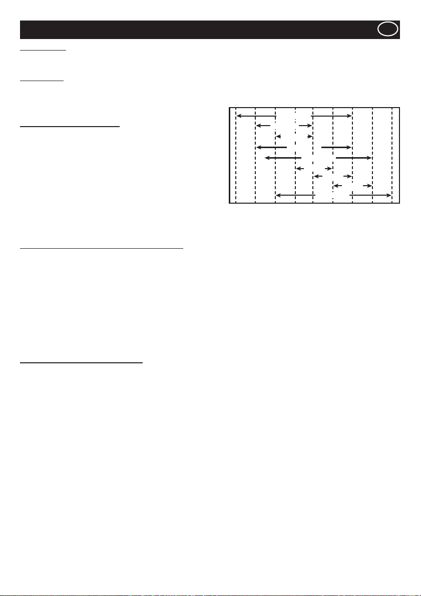
Assistência Técnica
GB
Óleo hidráulico
Ɣ Total EP32, Shell Tellus T37, MOBIL DTE15 or ESSO Unipower, XL46.
Óleo do motor
Seleccione a viscosidade do óleo do motor adequada com base na temperatura ambiente e utilize o grá¿ co do grau de viscosidade de
serviço SAE abaixo.
Neste equipamento, é utilizado SAE 15W-40 de fábrica.
Especi¿ cações do óleo do motor
Utilize um óleo do motor que cumpra ou exceda as seguintes directrizes
ou classi¿ cações:
Categorias de serviços
Ɣ Categorias de serviço API CD ou superior.
Ɣ Categorias de serviço ACEA E-3, E-4 e E-5
Ɣ Categoria de serviço JASO DH-1
De¿ nições
Ɣ Classificação API (American Petroleum Institute)
Ɣ Classificação ACEA (Association des Constructeurs Européens
d’automobiles)
Ɣ JASO (Japanese Automobile Standards Organisation)
30°F
(22°C)
(-20°C)
-4°F
SAE 10W
14°F
(-10°C)
SAE 5W-30
SAE 20W
SAE 10W-30
32°F
(0°C)
SAE 15W-40
SAE 20
SAE 30
SAE 20W-50
50°F
68°F
(10°C)
(20°C)
SAE 40
86°F
(30°C)
104°F
(40°C)
122°F
(50°C)
Procedimento de mudança do óleo do motor - Yanmar
1. Certi¿ que-se de que o rolo compressor se encontra numa superfície nivelada e o manípulo de operação na posição de
armazenamento. Aplique o travão de segurança.
2. Desaperte a porca na parte inferior do tampão de enchimento/escoamento do óleo. NOTA:- NÃO remova o tampão nesta fase.
3. Faça deslizar a mangueira do painel lateral.
4. Remova os 4 parafusos M8 ¿ xados utilizando uma chave inglesa de 13 mm. Remova o painel lateral.
5. Remova a mangueira do chassi, remova o tampão e escoe o óleo para um recipiente.
6. Volte a colocar o painel lateral utilizando uma chave inglesa de 13 mm e faça deslizar a mangueira de enchimento/escoamento do
óleo novamente para a ranhura no painel. Aperte a porca para ¿ xar ao painel lateral mas deixe o tampão removido.
7. Utilizando um funil, deite o óleo na mangueira de enchimento. O enchimento tem de ser realizado com cuidado para garantir que a
capacidade não é excedida. Utilize uma vareta do lado esquerdo do motor para veri¿ car o nível do óleo.
8. Volte a colocar o tampão de enchimento/escoamento do óleo.
9. Veri¿ que se o equipamento funciona correctamente.
Procedimento de substituição da bateria
1. Remova os 4 parafusos da protecção lateral utilizando uma chave de caixa de 13 mm e remova a protecção lateral. Guarde os
¿ xadores.
2. Utilizando uma chave inglesa de 11 mm, remova o cabo de terra da bateria e, em seguida, remova o cabo positivo da bateria.
3. Remova a braçadeira e a ¿ ta de isolamento da bateria. Remova as 2 porcas e as 2 anilhas utilizando uma chave inglesa de
13 mm.
4. Remova a anilha e o terminal longo da bateria utilizando uma chave inglesa de 13 mm.
5. Remova os 2 parafusos do regulador utilizando uma chave de caixa de 10 mm.
6. Remova o suporte por trás do regulador utilizando uma chave de caixa de 10 mm. Certi¿ que-se de que não desaperta o espaçador
por trás do suporte.
7. Mova a braçadeira de retenção do cabo À exível e puxe os ¿ os para fora.
8. Faça deslizar a bateria para fora e substitua pela bateria nova.
9. Coloque os ¿ os novamente no lugar e ¿ xe com a braçadeira de retenção do cabo.
10. Volte a colocar o suporte e o espaçador e aperte a 12 Nm.
11. Volte a colocar os 2 parafusos no regulador e aperte a 12 Nm.
12. Volte a colocar o terminal da bateria e a anilha e aperte a 28 Nm.
13. Volte a colocar a braçadeira e a ¿ ta de isolamento da bateria utilizando a chave inglesa de 13 mm. Aperte a porca assegurando
que estão expostos 8 mm de rosca.
67
Page 68
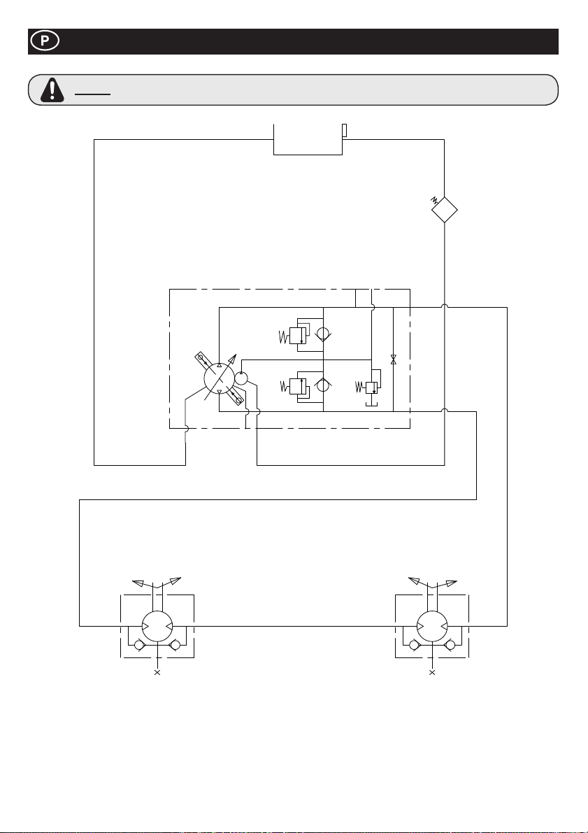
Circuito Hidráulico
AVISO
Se forem efectuadas reparações no circuito hidráulico, é necessário desenroscar parcialmente o tampão do
depósito, para garantir que o sistema não é pressurizado.
68
Page 69
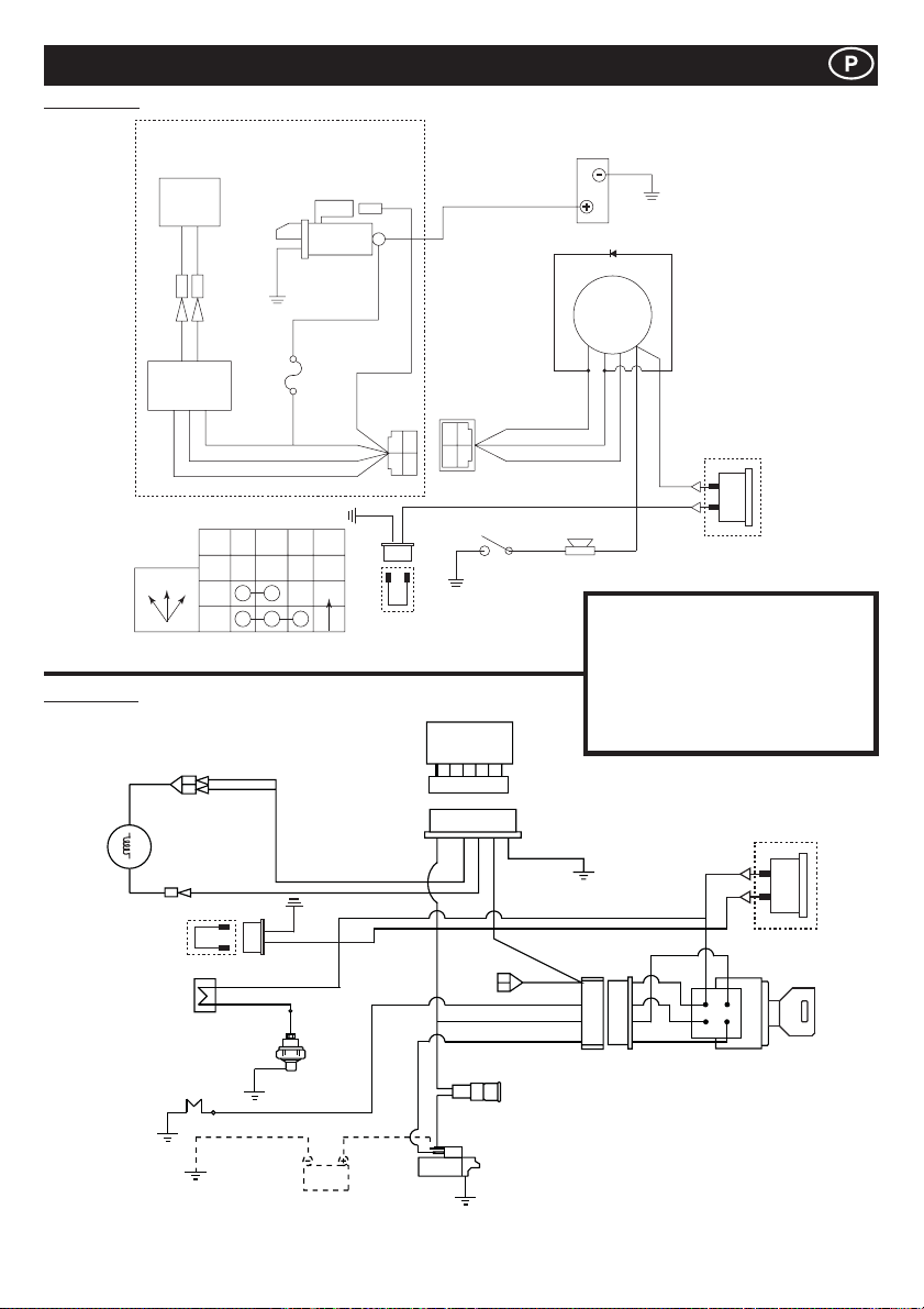
Yanmar L100N
Diagrama de Fiação
Kubota EA330
12V - 15A
Dínamo
G/W G/W
CB104 CB104
CA104 CA104
G/W G/W
Regulador
COMO O COMUTADOR DE CHAVE FUNCIONA
IG BAT ST NOTE
OFF
OFF12
1
2
Motor de arranque
12 v CC 0,8 kW
W
JAS0
D601
20T
AUTO
Y
W
G
Y
M8
Parafuso
R
YAZAKI NO.
7323-2446
RY
WG
B
BR
B
Hour fio Relógio
de Ligação
YAZAKI NO.
7322-2446
R
WG
Comutador de
pressão do óleo
Ter r a
Regulador
SBGBK
R
SB
AV2 0
AV1 .25
AV1 .25
AV1 .25
AV2 0
Comutador de chave
G
R
W
Sirene
Bateria
de terra
Díodo
BAT
(30)
IG
ST
(25)
(50)
(15)
Y
Y
Opção de Hora
de Relógio
Inventário
G = Verde IG = Ignição
W = Branco BAT = Bateria
Y = Amarelo ST = Arranque
R = Vermelho BK = Preto
BL = Azul SB = Céu Azul
OR = Laranja BR = Castanho
Y
Dinamo de
Ventilador
Hour ¿ o Relógio
de Ligação
BK/R
R
B
Cigarra
Interruptor
de óleo
Plugue de Fulgor
SB
BK
Y
BR
Bateria
R
Y
BR
BR
Y
Y
Y
W
W
BK/R
R
BK/W
Y
R
G
Opção de Hora
de Relógio
Interruptor de Arranque
R
Fusível
Arranque
69
Page 70
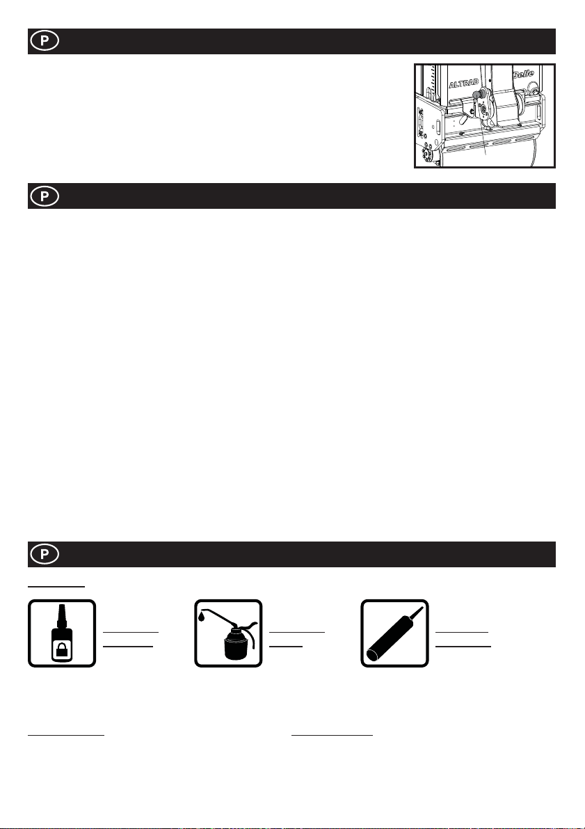
Armazenamento de Longa Duração
1. Na armazenagem de longa duração deve-se drenar o combustível restante do respectivo
depósito pelo orifício do Filtro de Combustível depois de ter retirado a taça do ¿ ltro ou pelo
Orifício de Entrada do Combustível utilizando um sistema de vasos comunicantes.
2. Limpar o Elemento do Filtro de Ar.
3. Limpar as eventuais acumulações de poeiras e óleos em todas as peças de borracha.
4. Limpar a placa base e aplicar uma leve camada de óleo para evitar a formação de ferrugem.
5. Cobrir a máquina e guardá-la em local seco.
6. A pega de operação pode ser levantada para facilitar o armazenamento. Premir a tranca e
levantar a pega. Certi¿ que-se que a tranca segura ¿ xamente a Pega de Operação.
TRAVA
Garantia
O seu novo compactador de “TDX” da Altrad Belle apresenta uma garantia para o comprador original durante um período de um ano
(12 meses) a partir da data efectiva de compra.
A garantia da Altrad Belle é contra defeitos de concepção, materiais e mão-deobra.
Os seguintes pontos não são cobertos pela garantia da Altrad Belle:
1. Danos causados por abuso, uso indevido, quedas ou outros danos semelhantes causados por ou como resultado de
incumprimento das instruções de montagem, operação ou manutenção do utilizador.
2. Alterações, adições ou reparações realizadas por pessoal exterior à Altrad Belle ou aos seus agentes autorizados.
3. Custos de transporte ou expedição de e para a Altrad Belle ou seus agentes autorizados para reparação ou avaliação por
conta de uma reclamação com base na garantia relativa a qualquer máquina.
4. Custos de material e/ou mão-de-obra para renovar, reparar ou substituir componentes devido a desgaste e usura normais.
Os seguintes componentes não estão cobertos pela garantia.
· Filtro de ar do motor
A Altrad Belle e/ou os seus agentes autorizados, directores, empregados ou seguradores não serão considerados responsáveis por
danos, perdas ou despesas, consequentes ou outros, relativos ou devido a incapacidade de usar a
máquina para qualquer ¿ nalidade.
Reclamações de Garantia
Todas as reclamações de garantia deverão ser primeiramente dirigidas ao Altrad Belle, por telefone, fax, E-mail ou por escrito.
Para reclamações de garantia:
Altrad Belle Warranty Department,
Sheen, Nr. Buxton,
Derbyshire SK17 0EU
England.
Informações de peças sobressalentes
LEGENDA
APLIQUE
LOCTITE
Para obter informações sobre a disponibilidade de peças sobressalentes para este equipamento, visite www.Belle247.com ou entre
em contacto com a ALTRAD Belle:-
# - Opção de cor 1 ## - Opção de cor 2
N.º de peça + S = Laranja (Eg. 981/05100S) N.º de peça + GR = Cinzento (Eg. 981/03200GR)
N.º de peça + G = Verde N.º de peça + GR2 = Cinzento quartzo
N.º de peça + B1 = Azul N.º de peça + BL = Preto
N.º de peça + R1 = Vermelho N.º de peça + W = Branco
N.º de peça + Y = Amarelo
N.º de peça + Y2 = Amarelo
APLIQUE
ÓLEO
70
ILICONE
S
APLIQUE
SILICONE
Page 71
Het gebruik van deze handleiding
Deze handleiding is een hulpmiddel om de ‘TDX’-wals op veilige wijze te bedienen en te onderhouden. Deze handleiding is bestemd
voor leveranciers en bedieners van de ‘TDX’-wals.
Voorword
In de sectie ‘Machinebeschrijving’ maakt u kennis met de inrichting en bedieningsorganen van de machine.
In de sectie ‘Milieu’ staan aanwijzingen over hoe u afgedankte machines op een milieuvriendelijke wijze kunt afvoeren voor recycling.
In de sectie ‘Algemene veiligheid’ en de sectie ‘Gezondheid en veiligheid’ wordt uitgelegd hoe u de machine dient te gebruiken om
uw veiligheid en de veiligheid van het grote publiek te kunnen waarborgen.
In de sectie ‘Bedieningsvoorschriften’ vindt u aanwijzingen voor het opstellen en gebruik van de machine.
Met behulp van de ‘Storingopzoekgids’ kunt u een mogelijk probleem met uw machine opsporen en verhelpen.
In de sectie ‘Onderhoud’ vindt u aanwijzingen m.b.t. onderhoudswerkzaamheden van algemene aard aan uw machine.
Richtlijnen met betrekking tot de notaties
Aandachtspunten in deze handleiding worden op de volgende wijze aangegeven:
VOORZICHTIG
The Het product kan aan een risico blootstaan. De machine kan schade oplopen of u kunt letsel
oplopen indien de procedures niet op de juiste wijze worden uitgevoerd.
WAARSCHUWING
Het leven van de bediener kan op het spel staan.
Veiligheidsvoorschriften
WAARSCHUWING
Zorg dat u WEET hoe u de machine op veilige wijze bedient en wat u moet doen om die in een veilige staat van onderhoud te
houden.
(N.B. Zorg dat u weet hoe u de machine moet uitschakelen voordat u die inschakelt, voor het geval dat u in moeilijkheden mocht
raken.)
Draag of gebruik ALTIJD de passende veiligheidsmiddelen die vereist zijn voor uw persoonlijke bescherming.
Mocht u VRAGEN hebben over het op veilige wijze gebruiken of onderhouden van deze machine, GA DAN NAAR DE UITVOERDER
OF NEEM CONTACT OP MET DE BELLE GROEP. (+44 (0)1298 84606)
Voordat u met deze machine gaat werken of er enig onderhoud aan gaat uitvoeren, moet u eerst
deze handleiding GOED BESTUDEREN.
Inhoudsopgave
Het gebruik van deze handleiding ........................................................................................................................................................... 71
Veiligheidsvoorschriften ............................................................................................................................................................................71
Technische gegevens ............................................................................................................................................................................... 72
Stickers ..............................................................................................................................................................................................73 - 74
Machinbeschrijving ...................................................................................................................................................................................75
Algemene veiligheid ................................................................................................................................................................................. 75
Gezondheid en veiligheid .........................................................................................................................................................................76
Controles bij stilstaande motor ................................................................................................................................................................ 76
Milieu ........................................................................................................................................................................................................76
Aan- en uitzetten ...................................................................................................................................................................................... 77
Bediening van de TDX 650A-wals ........................................................................................................................................................... 78
Onderhoud.........................................................................................................................................................................................78 - 80
Hydraulisch Circuit ...................................................................................................................................................................................81
Bedradingsschema ...................................................................................................................................................................................82
Langdurige opslag .................................................................................................................................................................................... 83
Garantie ....................................................................................................................................................................................................83
Informatie Reserveonderdelen .................................................................................................................................................................83
EG - Verklaring Van Overeenstemming .....................................................................................................................................................2
De Belle Groep behoudt zich het recht voor machinespeci¿ caties zonder voorafgaande kennisgeving of verplichting te wijzigen.
71
Page 72
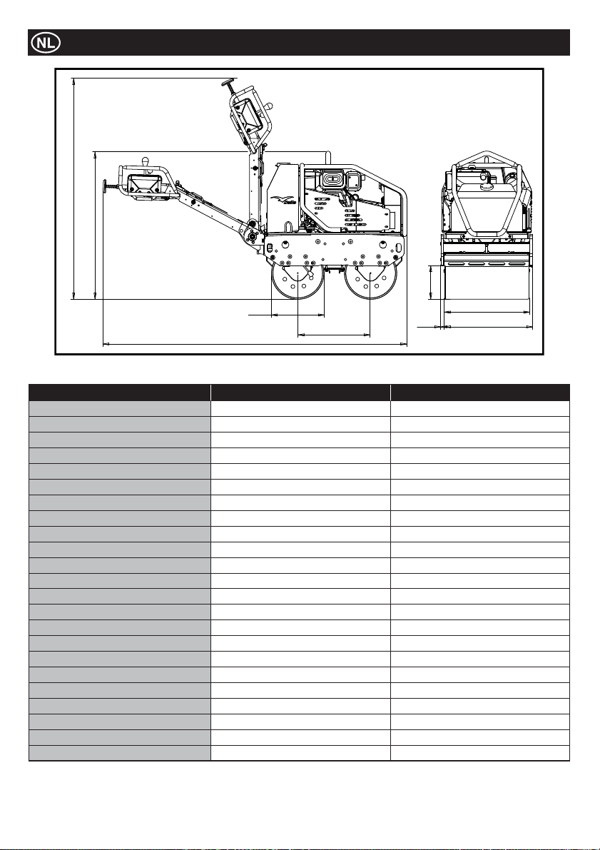
Technische Gegevens
J
B
G
D
A
Model TDX 650A Yanmar L100N TDX 650A Kubota EA330
Gewicht* - Kg 675 684
A - Totale lengte - mm 2318 2318
B - Totale hoogte - mm 1137 1137
C - Wielbasis - mm 560 560
D - Roldiameter - mm 402 402
E - Rolbreedte - mm 650 650
F - Totale breedte - mm 703 703
G - Draaicircel Tussen Stoepbanden - mm 258 258
H - Overstek - mm 26.5 26.5
J - Hoogte, Opslag - mm 1678 1678
Rijsnelheid (vooruit) - m/m (km/h) 0 - 70 (0 - 4.2) 0 - 70 (0 - 4.2)
Rijsnelheid (achteruit) - m/m (km/h) 0 - 38 (0 - 2.3) 0 - 38 (0 - 2.3)
Trilfrequentie - v.p.m 3300 3300
Centrifugaalkracht - kN 16 16
Inhoud waterreservoir - Ltr 65 65
Inhoud oliereservoir - Ltr 16 16
Motor YANMAR L100N KUBOTA EA330
Type 4-Takt luchtgekoeld 4-Takt watergekoeld
Brandstof Diesel Diesel
Inhoud brandstoftank - Ltr 5.4 4.8
Nominaal vermogen - Hp (kW) 9 (6.6) 5.9 (4.4)
Maximale Produktiet - Hp (kW) 10 (7.4) 6.9 (5.2)
Startsysteem Electrisch (met Recoil optie backup Start) Electrisch
* Het gewicht is zonder water in de watertank. Water in tank = 65 liter = 65 kilogram
C
H
E
F
72
Page 73
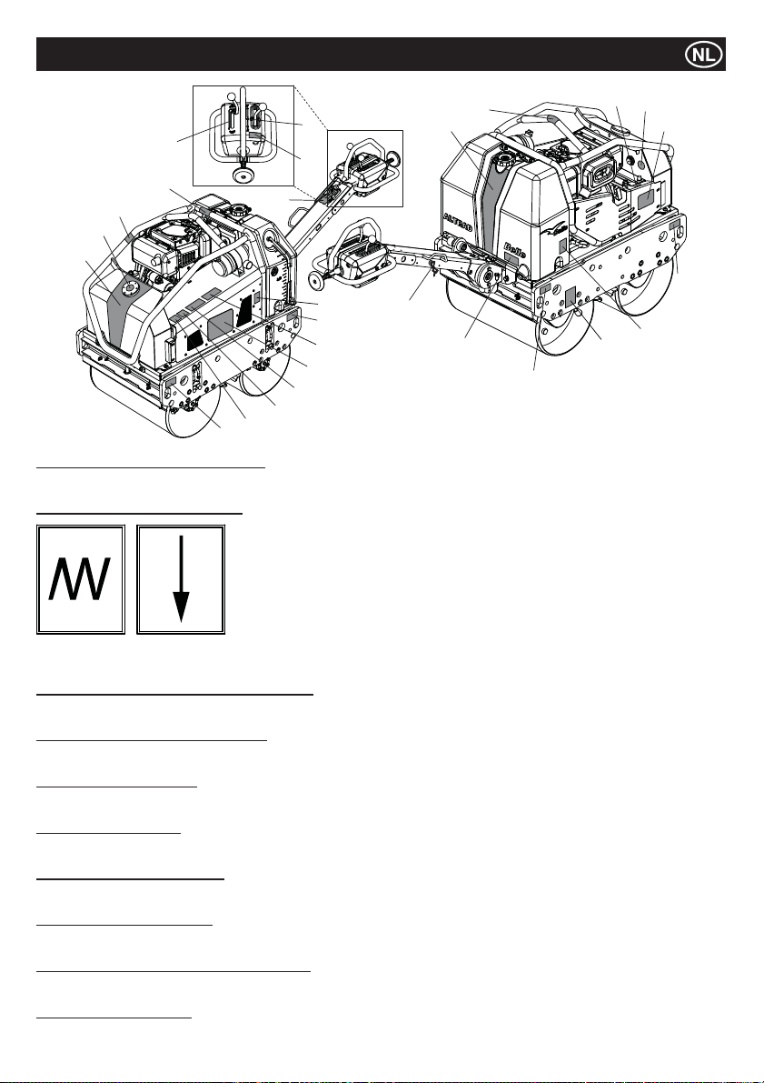
7
5
17
10
18
1
22
9
Artikelen 1 tot 4 – Stickers met merknaam
Merknaam stickers om de TDX Roller herkenbaar te maken.
Artikel 5 – Sticker voor vibratiehendel
6
21
8
9
25
3
24
23
Stickers
19
2
20
14
9
Opmerking:- De afbeelding toont de Yanmar L100N model.
13
15
12
4
9
16
Vibratie
ingeschakeld
Artikel 6 – Waarschuwing/Lees handleiding sticker
Waarschuwing! Lees a.u.b. de bedieningshandleiding voordat u de machine gebruikt.
Artikel 7 – Sticker vooruit/achteruit hendel
Hendel om de rijrichting van de machine te veranderen. F = vooruit, R = achteruit, Ɣ = vrijloop
Artikel 8 – Onderhoud sticker
Deze sticker geeft aan dat de kap kan worden weggenomen voor onderhoud van de motor.
Artikel 9 – Hijs/sjor sticker
Geeft de plaatsen aan waaraan de machine kan worden gehesen of vastgesjord bij transport.
Artikel 10 – Heet oppervlak sticker
Waarschuwing! Pas op hete oppervlakken rond de hydraulische tank en de uitlaat.
Artikel 11 – Olie bijvullen sticker
Laat zien waar de motorolie kan worden bijgevuld en waar het oliepeil kan worden gecontroleerd.
Artikel 12 – Sticker voor peilglas hydraulische olie
Geeft de plaats aan van het peilglas van de hydraulische olie dat het niveau van de hydraulische olie in de tank laat zien.
Artikel 13 – Oliesoort sticker
Legt uit wat voor soort olie moet worden gebruikt om de motor bij te vullen.
Vibratie
uitgeschakeld
73
Page 74
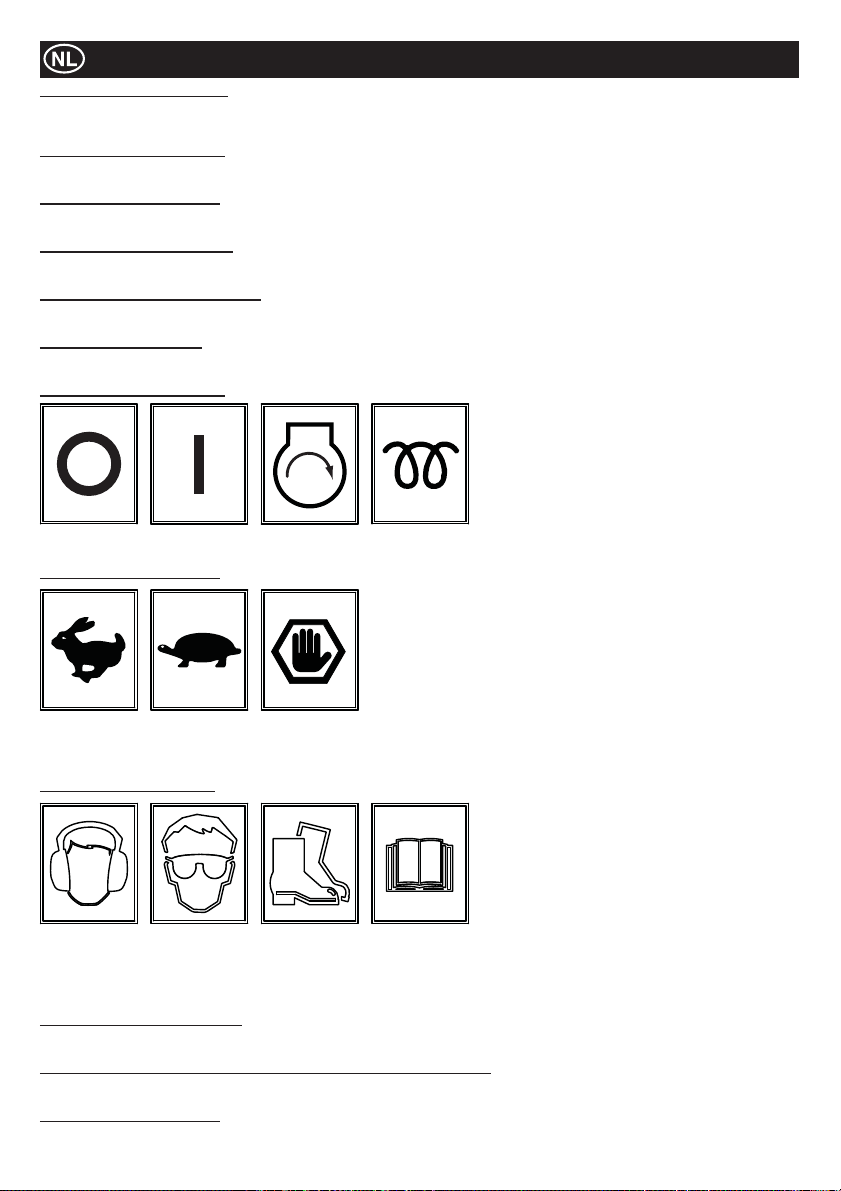
Stickers
Artikel 14 – Waterafvoer sticker
Als de voorspelde omgevingstemperatuur beneden nul graden is, moet de watertank worden geleegd door de stop uit waterafvoer te
halen.
Artikel 15 – Parkeerrem sticker
Geeft de plek aan van de parkeerrem. De parkeerrem moet worden ingeschakeld wanneer de machine niet in gebruik is.
Artikel 16 – Sproeibalk sticker
Toont de plek van de sproeibalk kranen en ook welke kraan voor welke sproeibalk is.
Artikel 17 – Alleen diesel sticker
De machine mag alleen worden gevuld met diesel!
Artikel 18 – Hydraulische olie sticker
Locatie van de vuldop van de hydraulische olie.
Artikel 19 – Hijsoog sticker
Hijsoog voor gebruik met een strop of een mechanische takel.
Artikel 20 – Startsleutel sticker
UIT AAN START
Artikel 21 – Gashendel sticker
Maximale
toeren
Vrijloop
stand
Noodstop
stand
WARMTE
(KUBOTA)
stand
Artikel 22 – Veiligheid sticker
Draag
gehoorbescherming
Artikel 23 – Geluidsniveau sticker
Het gegarandeerde geluidsniveau van de machine in dB(A).
Artikel 24 – Sticker Waarschuwing Uitlaatgassen (Onderdeel Nr. 800-99520)
Motoren geven koolmonoxide af; werken alleen in goed geventileerde ruimtes.
Artikel 25 – Beknelling sticker
Waarschuwing! Pas op voor de mechanische componenten als bewaker wordt verwijderd.
Draag een
veiligheids-
bril
Draag
veilig-
heidssch-
oenen
Lees a.u.b.
de
bediening-
shandlei-
ding
74
Page 75
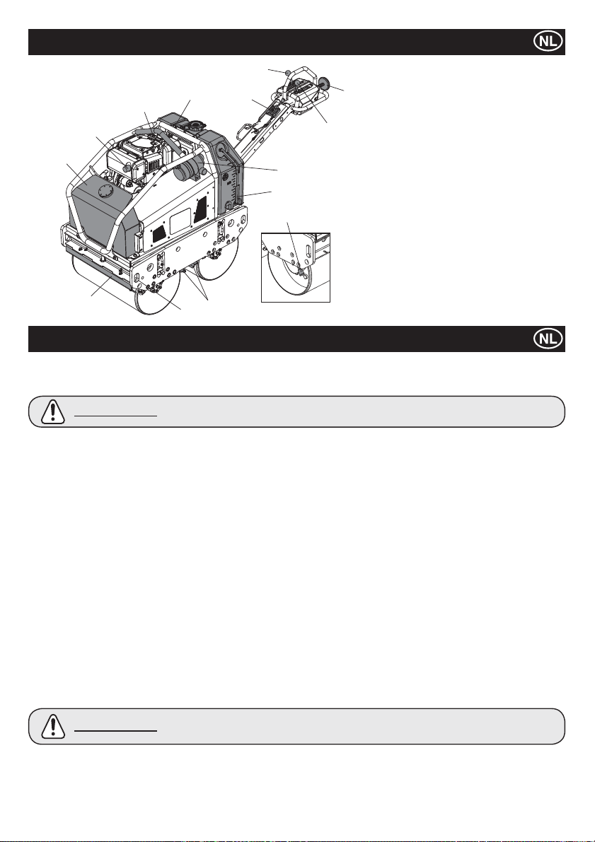
Machinebeschrivjing
5
1. Hydraulische-olietank.
2
12
1
10
4
11
8
3
9
13
10
7
2. Hijsoog
6
3. Lucht¿ lter
4. Waterreservoir.
5. Vooruit/achteruit-hendel.
6. Trilhendel.
7. Veiligheidshendel voor achteruitbeweging.
8. Gashendel.
9. Waterniveau peil
10. Schraapstang
11. Sjorpunten
12. Uitlaat
13. Parkeerrem
Opmerking:- De afbeelding toont de Yanmar
L100N model.
Algemene veiligheid
Bestudeer voor uw eigen bescherming en voor de veiligheid van degenen om u heen a.u.b. de onderstaande informatie m.b.t. de
veiligheid totdat u alles volledig begrepen heeft. Het is de verantwoordelijkheid van de bediener ervoor te zorgen dat hij/zij precies weet
hoe er veilig met dit materieel gewerkt kan worden. Als u er niet zeker van bent hoe u de ‘TDX’-wals op veilige en juiste wijze gebruikt,
ga dan naar uw uitvoerder of win advies in bij de Belle Groep.
VOORZICHTIG
Ɣ Deze machine mag uitsluitend gebruikt worden voor het doel waarvoor die bestemd is.
Ɣ
Deze machine mag uitsluitend door geoefend personeel bediend worden.
Ɣ
De eigenaar van deze machine moet de in het land van toepassing geldende Regeling m.b.t. de Arbeidsveiligheid in acht nemen,
en de gebruiker van de machine onderrichten in het naleven daarvan.
Ɣ
Gebruik een voor het doel geschikt hijswerktuig om de machine op te hijsen.
Met deze machine moet op een ondergrond gewerkt worden waar stabiliteit gewaarborgd is. Wanneer u nabij de rand van
Ɣ
uitgegraven sleuven werkt, gebruik de machine dan zo dat de sleuven niet instorten of dat de machine er niet invalt.
Ɣ
Indien het te verdichten oppervlak op een helling ligt, moet u zeer voorzichtig te werk gaan wat betreft de rijrichting van de machine.
Ga altijd recht een helling op en af, niet dwars eroverheen.
Ɣ
Zet het werkgebied af en houd toeschouwers en voorbijgangers en onbevoegd personeel op een veilige afstand.
Ɣ
De bediener is verplicht telkens persoonlijke beschermingsmiddelen (PBM) te dragen wanneer hij/zij deze machine gebruikt (zie
Gezondheid & Veiligheid).
Ɣ
Zorg dat u weet hoe u deze machine op veilige wijze kunt uitschakelen voordat u die inschakelt, voor het geval dat u in
moeilijkheden mocht raken.
Ɣ
Zet de motor altijd af voordat u er onderhoud aan gaat verrichten.
Ɣ
Tijdens gebruik kan de motor erg heet worden, laat de motor eerst afkoelen voordat u die aanraakt.
Ɣ
Laat de motor nooit lopen en laat de machine nooit onbeheerd achter.
Ɣ
Verwijder nooit, en verander nooit iets aan, beschermpanelen, ze zitten er voor uw bescherming. Controleer altijd of
beschermpanelen in goede staat verkeren en goed bevestigd zijn. Indien welke ervan ook beschadigd zijn of ontbreken, GA DAN
PAS WEER MET DE MACHINE WERKEN wanneer het beschermpaneel is teruggeplaatst of gerepareerd.
Ɣ
Werk niet met de machine wanneer u ziek bent, u zich moe voelt, of wanneer u onder invloed van alcohol of drugs verkeert.
Ɣ
Deze machine is zo ontworpen dat de mogelijke risico’s die uit het gebruik ervan voortvloeien, tot een minimum beperkt worden.
Toch blijven er WEL degelijk risico’s aan verbonden, maar deze restrisico’s zijn niet duidelijk herkenbaar, en kunnen persoonlijk
letsel of schade aan goederen, en mogelijk zelfs de dood, tot gevolg hebben. Indien zulke onvoorspelbare en onherkenbare
risico’s aan het licht komen, moet de machine onmiddellijk stilgezet worden, en moet de bediener of de uitvoerder passende
maatregelen nemen om dergelijke risico’s te elimineren. Soms is het noodzakelijk de fabrikant op de hoogte brengen van zo’n
voorval zodat deze met het oog op de toekomst tegenmaatregelen kan nemen.
Veilige omgang met brandstof
VOORZICHTIG
Zet de motor af en laat die afkoelen voordat u brandstof gaat tanken.
Ɣ
Ɣ
Rook NIET tijdens het tanken en laat ook geen open vuur in de directe omgeving toe.
Ɣ
Gebruik bij het tanken een geschikte trechter, en zorg dat u niet op de motor morst.
Ɣ
Gemorste brandstof dient onmiddellijk ongevaarlijk gemaakt te worden, m.b.v. zand. Indien u brandstof op uw kleren gemorst
hebt, trek dan andere kleren aan.
Ɣ
Bewaar brandstof in een goedgekeurd, voor dit doel gemaakt vat, uit de buurt van warmte- en ontstekingsbronnen.
Onoordeelkundig onderhoud kan gevaarlijk zijn. Lees deze sectie door en ga pas onderhouds- of
reparatiewerkzaamheden verrichten als u alles goed begrepen heeft.
Brandstof is licht ontvlambaar. Dit kan leiden tot letsel en schade aan goederen. Zet de motor
uit, doof alle open vlammen en rook niet tijdens het tanken van brandstof. Veeg eventueel
gemorste brandstof altijd op.
75
Page 76
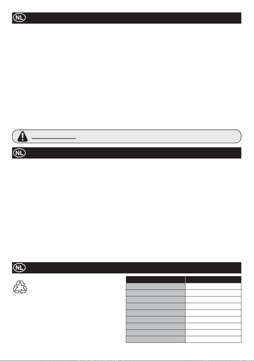
Gezondheid & Veiligheid
Trilling.
Bepaalde, tijdens het verdichtingswerk teweeggebrachte trillingen worden via de handgreep doorgegeven naar de handen van de
bediener. De ‘Minipac’ van de Belle Groep is speciaal ontworpen de hand-/armtrillingsniveaus te reduceren. Raadpleeg de sectie
Technische gegevens voor trillingsniveaus en gebruiksduur (aanbevolen maximale dagelijkse blootstellingsduur). Overschrijd de
maximale gebruiksduur NIET.
Persoonlijke beschermingsmiddelen (PBM).
Er moeten geschikte persoonlijke beschermingsmiddelen gedragen worden bij gebruik van deze machine d.w.z. veiligheidsbril,
handschoenen, gehoorbeschermers, stofmasker en schoeisel met een stalen neus (met antislipzolen voor extra veiligheid). Draag
kleding die geschikt is voor de werkzaamheden waar u mee bezig bent. Bescherm de huid altijd tegen contact met beton.
Stof.
Tijdens het verdichtingen kan stof vrijkomen, wat schadelijk kan zijn voor uw gezondheid. Draag altijd een masker dat geschikt is voor
het soort stof dat vrijkomt.
Brandstof.
Zorg dat u geen brandstof binnenkrijgt, adem ook geen brandstofdampen in en vermijd aanraking met de huid. Spoel brandstofspatten
onmiddellijk weg. Mocht u brandstof in de ogen krijgen: uitspoelen met overvloedige hoeveelheden water en zo spoedig mogelijk
medische hulp inroepen.
Uitlaatgassen
Werk met uw ‘TDX’-wals niet binnen of in een besloten ruimte, controleer of het werkgebied voldoende geventileerd wordt.
WAARSCHUWING
De door deze machine geproduceerde uitlaatgassen zijn zeer giftig en kunnen
dodelijk zijn!
Controles bij stilstaande motor
Controle vóór aanvang van de werkzaamheden
De volgende controle moet vóór aanvang van iedere werkperiode of na elke vier bedrijfsuren, welke van beide zich het eerst
voordoet, uitgevoerd worden. Raadpleeg de sectie Onderhoud voor gedetailleerde instructies. Indien er wat voor storing dan ook
wordt aangetroffen, mag de ‘TDX 650A Roller’ pas weer gebruikt worden als de storing is verholpen.
1. Inspecteer de machine grondig op tekenen van beschadiging.
2. Controleer slangen, vulopeningen, aftappluggen en andere plaatsen op tekenen van lekkage. Repareer eventuele lekken
alvorens met de machine te gaan werken.
3. Controleer het motoroliepeil en vul zo nodig olie bij.
3a. Zet de machine op een horizontaal oppervlak, en controleer het oliepeil van de motor.
3b. Verwijder de oliepeilmeter, en kijk of de olie tot aan de rand van de vulopening staat. Gebruik de juiste motorolie met de
juiste viscositeit (Raadpleeg a.u.b. de SAE onderhoud kwaliteit viscositeit kaart in de sectie onderhoud).
4. Controleer het motorbrandstofpeil en vul zo nodig brandstof bij. Gebruik schone brandstof. Bij gebruik van verontreinigde
brandstof kan het brandstofsysteem schade oplopen.
5. Controleer of het lucht¿ lter schoon is.
Als er zich te veel vuil/stof in het ¿ lterelement ophoopt, dan gaat de motor onregelmatig lopen. Reinig het lucht¿ lterelement
wanneer dat verontreinigd is (zie sectie Onderhoud).
6. Controleer de werking van de bedieningsorganen.
Controleer of de rijhendel, trilhendel, gashendel, parkeerhendel, en de beveiligingsinrichting voor de achteruitbeweging
soepel werkt.
7. Controleer het koelvloeistofniveau. Top tot ‘vullen’ niveau indien gewenst - KUBOTA ONLY!
Doelmatige verwijdering.
Voorschriften voor de bescherming van het milieu.
De machine bevat waardevolle materialen. Breng de
afgedankte machine en toebehoren naar een bedrijf dat
dergelijke machines op een milieuvriendelijke wijze
ontmantelt.
Milieu
Component Materiaal
Bedieningshendel Staal
Hoofdframe Staal
Hydraulische-olietank Staal
Waterreservoir Polyethyleen
Deksel Polyethyleen
Hydraulische pomp Staal en aluminium
Hydraulische motor Staal
Motor Staal en aluminium
Diverse onderdelen Staal, aluminium & rubber
76
Page 77
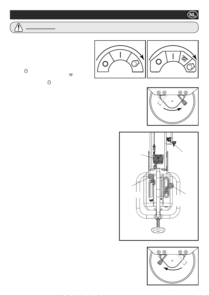
Aan- en uitzetten
VOORZICHTIG
Vergewis u er, alvorens de motor te starten, van dat de rijhendel in de vrijloop staat, de trilhendel in de stand UIT (OFF) staat,
en de parkeerhendel in de stand AAN (ON) staat.
1. Draai de brandstofkraan van de motor open.
2. Zet de gashendel op de bedieningsgreep in de stand
vol gas (haasje).
Starten van de motor – elektrische start
3ai. YANMAR - Draai de startsleutel bij de gashendel in de
Start
3aii. KUBOTA - Van koele, wacht warmte
gedurende 10 seconden. Draai de startsleutel bij de
gashendel in de Start
NIET voor een langere tijd de startmotor laten lopen! Maximaal 10 seconden.
3b. Zorg, nadat de motor loopt, dat de startsleutel tijdens het gebruik in de AAN (1) stand staat.
(Wanneer de sleutel in de UIT (0) stand wordt gezet, kan de generator de accu niet meer
laden.)
Starten van de motor – Handmatige start
4a. Neem de handgreep van de terugloop handstarter.
4b. Trek de handgreep langzaam naar u toe totdat u duidelijk weerstand voelt.
4c. Beweeg de handgreep langzaam terug naar de beginstand.
4d. Duw de decompressie hendel naar beneden en laat hem dan los. De decompressie hendel
zal automatisch teruggaan naar de oorspronkelijke stand wanneer de motor aanslaat.
4e. Neem de handgreep van de terugloopstarter.
4f. Trek de handgreep geheel naar buiten met een krachtige en gelijkmatige
beweging. Gebruik indien nodig twee handen.
4g. Beweeg de handgreep langzaam terug naar de beginstand.
4h. Wanneer de motor niet aanslaat, herhaal dan de procedure vanaf stap 4b.
5. Zet de gashendel in de stand LAAG en laat de motor enkele minuten in
zijn vrij lopen om op temperatuur te komen.
6. Als de motor op temperatuur is, is hij klaar voor gebruik.
7. Zet de gashendel snel in de hoge snelheid (H) stand om schade aan de
koppeling te voorkomen. De ‘vol gas’ stand van deze machine is in de
fabriek vooraf ingesteld om een optimale machineprestatie te
bewerkstelligen. Verander deze instellingen NIET want dit kan leiden tot
voortijdige slijtage en schade en de garantie van zowel de motor als de
machine zal hierdoor automatisch vervallen.
8. Beweeg de hendel van de parkeerrem naar rechts om de rem uit te
schakelen.
OPMERKING: Verzuimen de parkeerrem uit te schakelen vóórdat er met
de machine wordt gereden, leidt tot ernstige schade aan het
parkeerremmechanisme en aan het voorbewegingsmechanisme.
9. Bedieningspaneel
9a. Gashendel
Laat altijd tijdens het gebruik de gashendel in de stand Hoog staan.
Probeer NIET de rijsnelheid aan te passen door het toerental van de
motor te veranderen.
9b. Vooruit/achteruit hendel
Beweeg de hendel naar voren om de machine vooruit te laten rollen.
Beweeg de hendel naar achteren om de machine achteruit te laten rollen.
9c. Vibratiehendel
Door de vibratiehendel in de stand AAN te zetten, wordt het vibratie
mechanisme in werking gesteld.
10. Uitschakelen van de motor
11. Zet ter voorbereiding van het uitschakelen van de motor de gashendel
naar de stand LAAG.
12. Laat de motor een tot drie minuten in zijn vrij lopen.
13. Zet de gashendel in de stand STOP om de motor uit te schakelen. Zet daarna de sleutel in
de stand ‘UIT’. De zoemer klinkt wanneer de sleutel in de stand ‘AAN’ staat terwijl de motor
is uitgeschakeld.
14. Draai de brandstofkraan dicht.
15. Zet de machine in de parkeerrem door de hendel van de parkeerrem naar links te bewegen.
stand, en houd hem daar tot de motor aanslaat.
Haal uw handen NIET van de aanzetslinger af tijdens het starten.
YANMAR KUBOTA
positie
stand, en houd hem daar tot de motor aanslaat.
GASHENDEL
VIBRATIE-
HENDEL
UITSCHAKELEN
STARTSLEUTEL
VOORUIT/
ACHTERUIT
HENDEL
INSCHAKELEN
77
Page 78

Bediening van de TDX-wals
Ɣ
Na voltooiing van de in de sectie ‘Controles bij stilstaande motor’ vermelde controles, kunt u de motor aanzetten.
De met de hand gevoerde walsen uit de TDX-serie van de Belle Groep zijn voorzien van een centrifugaalkoppeling; hierdoor kan de motor
stationair lopen zonder de hydraulische pomp aan te drijven.
Ɣ
Naarmate het toerental van de motor toeneemt, zal de koppeling inschakelen en zal de motor de hydraulische pomp gaan aandrijven
en zal er hydraulisch vermogen geleverd worden om niet alleen de rollen maar ook het trilmechanisme aan te drijven. Zet om mogelijke
beschadiging van de centrifugaalkoppeling te vermijden, de gashendel snel van de stand L in de stand H. Voor een juiste werking dient het
motortoerental op het maximum gezet te worden tijdens het verdichten.
Ɣ
Werk niet met de machine op een volledig verdicht, hard, of niet-meegevend oppervlak. Anders lopen de lagers en andere mechanische
componenten schade op, als gevolg waarvan de levensduur van de machine drastisch bekort wordt.
Ɣ
Wanneer u op een steile helling werkt, dient u er voor te zorgen dat de machine altijd bij de helling naar beneden rolt.
Werk altijd bij de helling omhoog of bij de helling naar beneden, nooit langs de helling. Wanneer de machine wordt geparkeerd op een
helling, gebruik dan altijd de parkeerrem.
Ɣ
Zorg dat u wanneer de machine achteruitloopt, niet achter de bedienings-handgreep staat. Loop altijd naast de bedieningshandgreep, met
uw gezicht in de rijrichting gekeerd.
Ɣ
Hijsen
Wanneer u met behulp van hijsgereedschap de TDX 650A op zijn plaats wilt brengen, verzeker u er dan van dat het hijsgereedschap
een capaciteit heeft passend bij het gewicht van de machine (zie de tabel met technische gegevens). Bevestig geschikte kettingen
of hijsbanden UITSLUITEND aan de hijspunten die midden op de machine (hijsoog) of bij de hoeken van de machine (sjorpunten) zijn
aangebracht.
Ɣ
TRANSPORT
Transport op een voertuig.
Vergeet niet de handgreep te vergrendelen en gebruik geschikte oprijplaten met een toereikende breedte, lengte en sterkte voor het laden
en lossen van de machine op en van het voertuig.
Ɣ
Zet de machine op de parkeerrem en veranker de machine stevig voor transport op het voertuig.
Onderhoud
Met de hand gevoerde walsen uit de TDX-serie van de Belle Groep zijn zo degelijk geconstrueerd dat ze jarenlang probleemloos
werken. Het is echter belangrijk dat het eenvoudige, in deze sectie beschreven geregeld onderhoud wordt uitgevoerd. Aanbevolen
wordt al het grote onderhoud en grote reparaties door een door de Belle Groep erkende dealer te laten uitvoeren. Gebruik altijd
originele vervangingsonderdelen van de Belle Groep, het gebruik van niet-originele onderdelen kan uw garantie ongeldig maken.
Voordat onderhoud wordt gepleegd aan de machine dient u de motor uit te schakelen en de sleutel uit het contactslot te nemen.
Zet de machine altijd op een horizontale ondergrond neer zodat het peil van vloeistoffen correct afgelezen wordt.
Gebruik uitsluitend aanbevolen oliën (Zie pagina 80).
Onderhoud aan de motor
Voer het onderhoud aan de motor uit overeenkomstig de speci¿ caties van de fabrikant van de motor. Raadpleeg hiervoor het bedienings-
en onderhoudshandboek van de motor.
Opmerking: zorg er als de onderhoudskap is verwijderd voor dat alle schroeven stevig zijn vastgemaakt voordat u het apparaat weer
in gebruik neemt. Start de machine nooit wanneer beveiligingen zijn verwijderd.
Onderhoud: Om de 8 uur of dagelijks
1. Controleer op loszittende moeren en bouten, trek ze zo nodig na.
2. Controleer en reinig het lucht¿ lterelement, smeer het element weer in overeenkomstig de aanbevelingen van de fabrikant van de
motor. Indien de bedrijfsomstandigheden abnormaal stof¿ g en veeleisend zijn, dient het ¿ lterelement vaker gereinigd te worden.
3. Controleer het motoroliepeil voor de operatie.
Onderhoud: Na de eerste 50 uur en elke 200 uur daarna
1. Ververs de motorolie - zie procedure op pagina 80.
78
Page 79
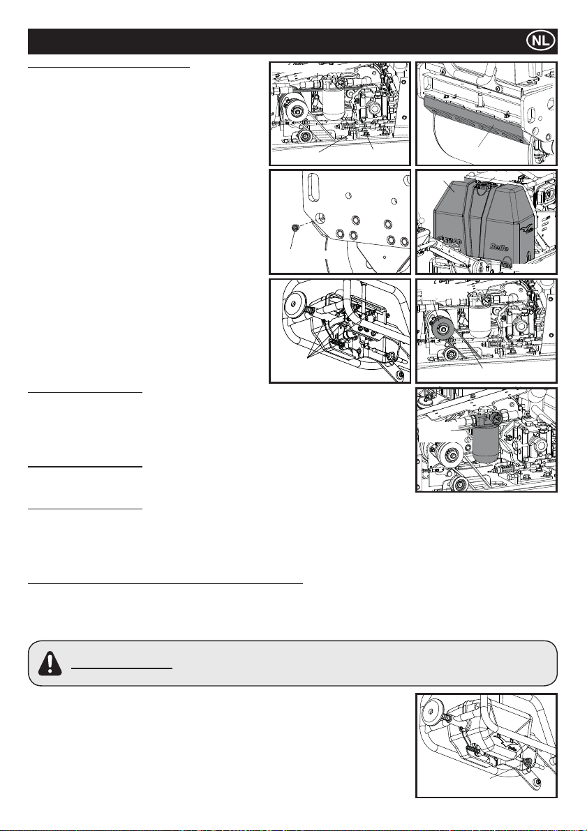
Onderhoud
Onderhoud: Om de 50 uur of wekelijks
1. Controleren van de spanning van de aandrijfsnaar
1a. Draai de vier bouten waarmee de pompsteun is
bevestigd, los en draai aan de stelbout totdat de juiste
spanningis bereikt. De snaar dient in het midden tussen
de centrifugaalkoppeling en de pomppoelie 5 mm door
te buigen.
1b. Draai de vier bouten van de pompsteun aan.
een nieuwe snaar wanneer de oude versleten is of er
scheurtjes in zitten.
2. Afstellen van de speling van de schraper
2a. Verwijder de schraper en ontdoe het van alle vuil, modder
en asfalt.
2b. Breng de schraper weer aan op de steun ervan, en zet die
vast met voldoende speling ten opzichte van de rol.
3. Waterreservoir
3a Laat al het water weglopen en reinig de tank van
binnen met een waterslang.
4. Sprenkelkop
4a. Haal de dop van de kop af, en maak de sprenkelkop
aan de binnenkant schoon.
5. Bewegende delen
5a. Smeer het stangeind van de kabel voor de
aandrijving/trilling in met vet.
5b. Vet de vetpunten van de bedieningshendel opnieuw in.
5c. Smeer de vibrator as
Onderhoud: Om de 100 uur
1. Koppelingsmechanisme van de trileenheid
1a. Controleer of het koppelingsmechanisme van de trileenheid naar behoren werkt.
1b. Smeer het bewegende deel met vet.
1c. Controleer de staat van de V-snaar. Monteer een nieuwe snaar wanneer de oude versleten
is of er scheurtjes in zitten.
Onderhoud: Om de 500 uur
1. Vervang het element van het hydraulische-olie¿ lter om de 500 bedrijfsuren.
Gebruik een ‘origineel’ ¿ lterelement.
Onderhoud: Om de 800 uur
1. Ververs de hydraulische olie.
Spoel het reservoir door alvorens het te vullen met de nieuwe hydraulische olie.
Laat de lucht uit het hydraulisch systeem ontsnappen door het deksel van het reservoir open te laten en de motor 10 minuten lang
op het maximumtoerental te laten lopen zonder de rijhendel en trilhendel te bedienen. Breng daarna het deksel van het reservoir
weer aan.
AFSTELLEN VAN DE VRIJLOOPINSTELLING VAN DE RIJHENDEL
De vrijloopstand van de rijhendel kan verschuiven ten gevolge van de trilling of slijtage van de aandrijfkabels. Ga als volgt te werk om
de vrijloopinstelling af te stellen:
1. Zet de machine op een horizontaal oppervlak neer.
2. Zet de motor af.
3. Draai de moer waarmee het stangeind van de aandrijfkabel aan de rijhendel is bevestigd eraf.
WAARSCHUWING
4. Draai de borgmoer op het stangeind los.
5. Draai het stangeind ofwel met de wijzers van de klok mee ofwel tegen de wijzers van de
klok in, afhankelijk van de richting waarin de vrijloopstand is verschoven.
6. Breng het stangeind weer aan op de aandrijfkabel en borg dat met de moer.
7. Start de motor en voer het toerental van de motor op tot het maximum. Kijk of de
vrijloopstand correct is afgesteld.
8. Is dat niet het geval, zet dan de motor af, verwijder de moer en herhaal punt 5 t/m 7 van de
procedure totdat de vrijloopstand correct is afgesteld.
9. Wanneer de vrijloopstand juist is afgesteld, breng dan Loctite aan op de moer waarmee het
stangeind is bevestigd en draai die vast. Draai vervolgens de borgmoer op het stangeind aan.
Monteer
Probeer niet de motor te starten wanneer deze moer niet op z’n plaats is bevestigd. De
machine kan dan plotseling en onvoorspelbaar gaan bewegen zonder dat die onder controle
gehouden kan worden met de rijhendel, wat ernstig letsel of schade aan goederen tot gevolg
kan hebben.
AANDRIJFRIEM
RIEM REGELAAR
SPRENKELKOP
SMEER
PUNTEN
79
KLAMPBOUT
RESERVOIR
VIBRATIE
KOPPELING
FILTER
ELEMENT
BORGMOER
SCHRAPER
DOP
AFTAPPEN
V-SNAAR
Page 80
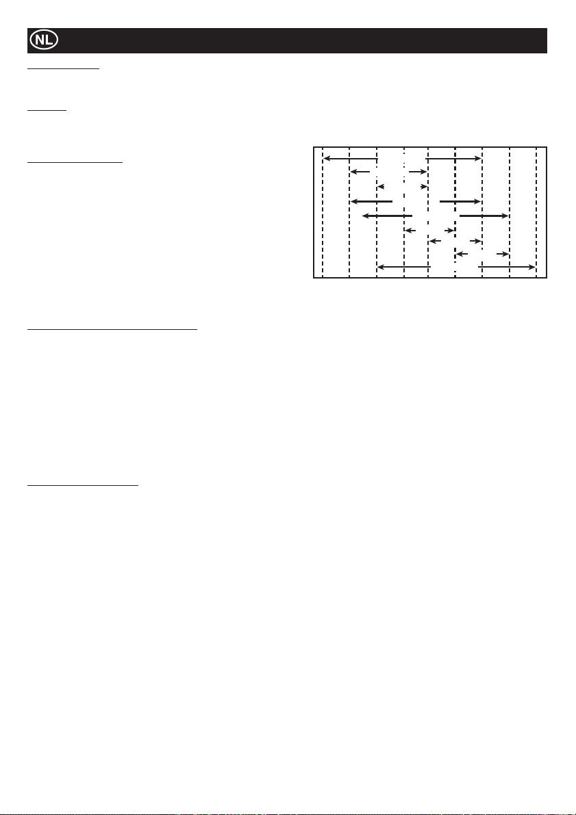
Onderhoud
Hydraulische olie
Ɣ Total EP32, Shell Tellus T37, MOBIL DTE15 or ESSO Unipower, XL46.
Motorolie
Selecteer de juiste olieviscositeit gebaseerd op de omgevingstemperatuur en gebruik de SAE onderhoud kwaliteit viscositeit kaart
hieronder. Deze machine is in de fabriek gevuld met SAE 15W-40.
-4°F
SAE 10W
14°F
(-10°C)
SAE 5W-30
SAE 20W
SAE 10W-30
32°F
(0°C)
SAE 15W-40
SAE 20
SAE 30
SAE 20W-50
50°F
68°F
(10°C)
(20°C)
SAE 40
86°F
(30°C)
104°F
(40°C)
122°F
(50°C)
Speci¿ caties motorolie
Gebruik motorolie die voldoet aan of beter presteert dan de volgende
richtlijnen en classi¿ caties:
Onderhoudsklasse
Ɣ API onderhoudsklasse CD of hoger.
Ɣ ACEA onderhoudsklasse E-3, E-4 en E-5
Ɣ JASO onderhoudsklasse DH-1
De¿ nitions
Ɣ API Classificatie (American Petroleum Institute)
Ɣ ACEA Classificatie (Association des Constructeurs Européens
d’automobilies)
Ɣ JASO (Japanese Automobile Standards Organisation)
30°F
(22°C)
(-20°C)
Procedure vervangen motorolie - Yanmar
1. Zorg er voor dat de Roller op een horizontaal oppervlak staat en dat de bedieningshendel in de opslag positie staat. Gebruik de
parkeerrem.
2. Maak de moer aan de onderkant van de vul/aftap stop los. LET OP:- verwijder de stop nog niet!
3. Schuif de slang van het zijpaneel.
4. Verwijder de vier M8 stelschroeven met een moersleutel 13 mm. Verwijder het zijpaneel.
5. Neem de slang uit het chassis, verwijder de stop en tap de olie af in een bak.
6. Monteer het zijpaneel weer met de moersleutel 13 mm en schuif de olie vul/aftap slang terug in de sleuf in het paneel. Draai de
moer vast om hem aan het zijpaneel te bevestigen, maar laat de stop er nog af.
7. Giet met behulp van een trechter olie in de vulslang. Het vullen moet zorgvuldig gebeuren om niet de capaciteit te overschrijden.
Gebruik de peilstok aan de linkerkant van de machine om het oliepeil te controleren.
8. Schroef de olie vul/aftap stop weer op zijn plek.
9. Controleer of de machine correct functioneert.
Procedure vervangen accu
1. Verwijder de vier bouten van de zijbeschermplaat met behulp van een inbussleutel 13 mm en verwijder de zijbeschermplaat. Be
waar de bouten.
2. Verwijder met behulp van een moersleutel 11 mm de aardkabel van de accu, verwijder daarna de pluskabel van de accu.
3. Verwijder de accuklem en de vilten ringetjes. Verwijder twee moeren en twee ringetjes met behulp van een moersleutel 13 mm.
4. Verwijder de lange accubout en ring met behulp van een moersleutel 13mm.
5. Verwijder twee bouten van de regulateur met behulp van een inbussleutel 10 mm.
6. Verwijder het bracket achter de regulateur met behulp van een inbussleutel 10 mm. Pas op niet de afstandhouder van achter het
bracket kwijt te raken.
7. Beweeg de À exibele kabelklemband en trek de kabels weg.
8. Neem de accu weg en plaats een nieuwe accu.
9. Zet de kabels terug op hun plek en bevestig ze met de kabelklemband.
10. Monteer het bracket en de afstandhouder en draai dit vast met 12 Nm.
11. Monteer de twee bouten terug in de regulateur en draai ze vast met 12 Nm.
12. Monteer de accubout en ring en draai de bout vast met 28 Nm.
13. Monteer de accuklemmen en vilten ringen met een moersleutel 13 mm. Draai de moeren vast zo dat er 8 mm draad zichtbaar is.
14. Bevestig de pluskabel aan de accu en daarna de aardkabel.
15. Monteer de zijbeschermplaat. Draai de vier bouten vast met 28 Nm.
80
Page 81
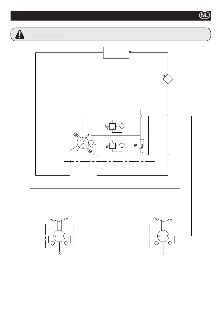
WAARSCHUWING
Hydraulisch Circuit
Wanneer er reparaties worden uitgevoerd aan het hydraulische systeem moet de vuldop
van de tank worden losgedraaid om er zeker van te zijn dat het systeem niet onder druk
staat.
81
Page 82
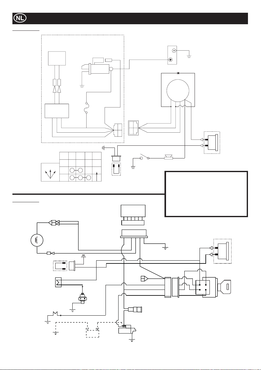
Yanmar L100N
Bedradingsschema
Kubota EA330
12V - 15A
Dynamo
G/W G/W
CB104 CB104
CA104 CA104
G/W G/W
Regelaar
FUNCTIES SLEUTELSCHAKELAAR
IG BAT ST NOTE
UIT
OFF12
1
2
Y
Startmotor
12 V gelijkstroom 0,8 kW
Schroef
W
JAS0
D601
20T
AUTO
W
G
Y
R
YAZAKI NO.
7323-2446
B
Uurs Klok
Koppeling Draad
M8
RY
B
WG
BR
Regelaar
R
YAZAKI NO.
7322-2446
R
WG
Oliedrukschakelaar
Aardpool
Y
SBGBK
SB
AV2 0
AV1 .25
AV1 .25
AV1 .25
AV2 0
Diode
Sleutelschakelaar
BAT
(30)
ST
IG
(15)
(50)
G
R
W
Hoorn
Aardpool
accu
(25)
Y
Y
Inventaris
G = Groen IG = Ontsteking
W = Wit BAT = Battery
Y = Geel ST = Accu
R = Rood BK = Zwart
BL = Blauw SB = Hemelsblauw
OR = Oranje BR = Bruin
Uurs Klok
Optie
Fan
Dynamo
Uurs Klok
Koppeling Draad
BK/R
R
B
Zoemar
Oilschakelaar
Gloeibougie
SB
BK
Y
BR
Battery
BR
BK/W
BR
W
BK/R
Y
Y
Y
W
Uurs Klok
Optie
Y
G
R
R
Y
R
startschakelaar
R
Fuse
Start
82
Page 83
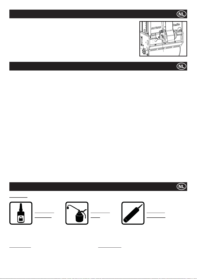
Landurige opslag
1. Voor langdurige opslag de brandstof verwijderen uit de Brandstoftank door de resterende
brandstof eruit te zuigen via de Brandstofvulopening of via het Brandstof¿ lter na verwijdering
van de ¿ lterbeker.
2. Maak het Lucht¿ lter-element schoon.
3. Verwijder olie- en stofresten van alle rubber delen.
4. Maak de bodemplaat schoon en breng een olielaag aan om roestvorming te voorkomen.
5. Dek de machine af en sla die op een droge plaats op.
6. De bedieningshendel kan bij opslag rechtop gezet worden. Trek aan de Pal en zet de
hendel rechtop. Zorg ervoor dat de Pal de Bedieningshendel op veilige wijze blokkeert.
KLINK
Garantie
De Altrad Belle verleent u als de oorspronkelijke koper een garantie gedurende één jaar (12 maanden), gerekend vanaf de
oorspronkelijke aankoopdatum, op uw nieuwe TDX-wals.
De garantie van de Altrad Belle dekt ontwerp-, materiaal- en constructiefouten.
Het volgende is uitgesloten van de garantie van de Altrad Belle:
1. Schade ontstaan door verkeerd gebruik, misbruik, laten vallen of andere gelijkaardige schade ontstaan door of als gevolg van
het niet opvolgen van montagevoorschriften, bedieningsvoorschriften of voorschriften voor onderhoud door de gebruiker.
2. Door andere personen dan van de Altrad Belle of hun erkende vertegenwoordigers uitgevoerde wijzigingen, toevoegingen of
reparaties.
3. Transport- of expeditiekosten van en naar de Altrad Belle of hun erkende vertegenwoordigers, voor reparatie of beoordeling
van de kosten m.b.t. een garantie-aanspraak, op elke machine.
4. Materiaal- en/of arbeidskosten m.b.t. het vernieuwen, repareren of vervangen van componenten vanwege normale slijtage.
De volgende componenten vallen niet onder de garantie:
· Motorlucht¿ lter
De Altrad Belle en/of hun erkende vertegenwoordigers, directeuren, werknemers of verzekeraars zullen niet aansprakelijk gesteld
worden voor indirecte of andere schade, verliezen of kosten in verband met of wegens het feit dat de machine niet voor het doel
gebruikt kan worden waarvoor die bestemd is.
Garantie-aanspraken
Alle garantie-aanspraken dienen eerst bij de Altrad Belle ingediend te worden, per telefoon, fax, e-mail of schriftelijk.
Voor garantie-aanspraken:
Altrad Belle Warranty Department,
Sheen, Nr. Buxton,
Derbyshire SK17 0EU
England.
Informatie reserveonderdelen
SLEUTEL
GEBRUIK
LOCTITE
Voor informatie over reserveonderdelen die beschikbaar zijn voor deze machine kunt u www.Belle247 raadplegen of contact opnemen
met ALTRAD Belle waarbij u de volgende contactgegevens kunt gebruiken:
# - Kleuroptie 1 ## - Kleuroptie 2
Onderdeelnummer + S = oranje (bijv. 981/05100S) Onderdeelnummer + GR = grijs (bijv. 981/03200GR)
Onderdeelnummer + G = groen Onderdeelnummer + GR2 = quartzgrijs
Onderdeelnummer + B1 = blauw Onderdeelnummer + BL = zwart
Onderdeelnummer + R1 = rood Onderdeelnummer + W = wit
Onderdeelnummer + Y = geel
Onderdeelnummer + Y2 = geel
GEBRUIK
OLIE
ILICONE
S
GEBRUIK
SILICONE
83
Page 84
Anvendelse af denne manual
Denne manual er udarbejder for at hjælpe dig med sikkert at anvende og vedligeholde ‘TDX 650A’ Vibrationstromlen.
Manualen er tiltænkt forhandlere og brugere af ‘TDX 650A ’ Vibrationstromlen.
Forord
Afsnittet ‘Beskrivelse af maskinen’ hjælper dig med at gøre dig bekendt med maskinens indretning og styreenheder.
Afsnittet ‘Miljø’ giver instrukser i hvorledes genanvendelsen af udrangerede apparater skal håndteres på en miljøvenlig måde.
Afsnittene ‘Generelle sikkerhedsinstruktioner’ og ‘Helbred og Sikkerhed’ forklarer hvordan maskinen skal betjenes for at sikre
både din egen og offentlighedens sikkerhed.
Afsnittet ’Driftsvejledninger’ beskriver hvordan maskinen skal anvendes korrekt.
‘Fejl¿ ndingsguiden’ hjælper dig hvis der opstår et problem med din maskine.
Afsnittet ‘Service og Vedligeholdelse’ hjælper dig med den generelle vedligeholdelse og servicering af din maskine.
Retningslinier i forbindelse med piktogrammer.
Tekst i denne manual, som kræver særlig opmærksomhed, er markeret på følgende måde:
FORSIGTIG
Produktet kan medføre fare. Både maskinen og dig selv kan blive påført skader eller blive såret hvis
procedurerne ikke udføres på den korrekte måde.
ADVARSEL
Der kan være fare for operatørens liv
ADVARSEL
ADVARSEL
Vær sikker på at du ved hvordan maskinens styreenheder betjenes sikkert, og hvad du i øvrigt skal gøre for at sikre ufarlig vedligeholdelse.
(NB. Inden du tænder maskinen, skal du sikre dig, at du ved hvordan den slås af, hvis du skulle komme i vanskeligheder.)
Du skal ALTID bære eller anvende passende sikkerhedsudstyr som er påkrævet for at sikre din personlige sikkerhed.
Hvis du SPØRGSMÅL vedrørende sikker anvendelse eller vedligeholdelse af denne enhed, så ret henvendelse til din OVERORDNEDE
ELLER TAG KONTAKT MED Altrad Belle, Tlf. +44 (0)1298 84606.
Inden du tager maskinen i anvendelse eller foretager vedligeholdelsesarbejder på den, SKAL DU HAVE
LÆST og SAT DIG IND I denne manual.
Contents
Anvendelse af denne manual ...................................................................................................................................................................84
Advarsel....................................................................................................................................................................................................84
Tekniske data............................................................................................................................................................................................85
Mærkater ...........................................................................................................................................................................................86 - 87
Beskrivelse af maskinen ...........................................................................................................................................................................88
Generelle Sikkerhedsinstruktioner............................................................................................................................................................88
Helbred og Sikkerhed ...............................................................................................................................................................................89
Kontrol inden start ....................................................................................................................................................................................89
Miljø ..........................................................................................................................................................................................................89
Start- og standsningsprocedurer ..............................................................................................................................................................90
Betjening af TDX 650A Vibrationstromlen ................................................................................................................................................91
Service og vedligeholdelse ................................................................................................................................................................91 - 93
Hydraulisk Circuit......................................................................................................................................................................................94
Ledningsdiagram ......................................................................................................................................................................................95
Længerevarende opmagasinering............................................................................................................................................................96
Garanti ......................................................................................................................................................................................................96
Oplysninger om reservedele ....................................................................................................................................................................96
Overensstemmelseserklæring ....................................................................................................................................................................2
Altrad Belle forbeholder sig ret til at ændre maskinens speci¿ kationer uden forudgående bekendtgørelse eller forpligtelse.
84
Page 85
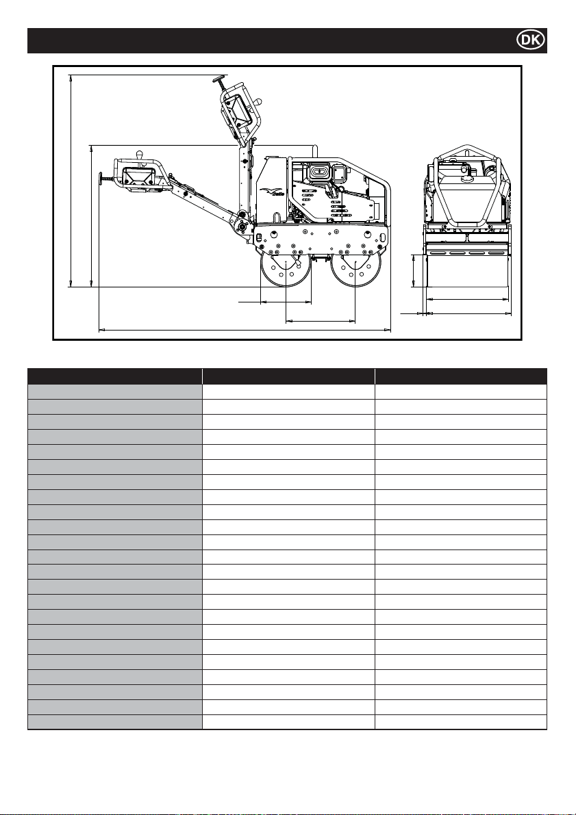
Tekniske Data
J
B
G
D
A
Model TDX 650A Yanmar L100N TDX 650A Kubota EA330
Vægt* - Kg 675 684
A - Længde i alt - mm 2318 2318
B - Højde i alt - mm 1137 1137
C - Akselafstand - mm 560 560
D - Tromlediameter - mm 402 402
E - Tromlebredde - mm 650 650
F - Bredde i alt - mm 703 703
G - Fri højde - mm 258 258
H - Sidelæns udbygning - mm 26.5 26.5
J - Højde ved opmagasinering - mm 1678 1678
Kørselshastighed (frem) - m/m (km/h) 0 - 70 (0 - 4.2) 0 - 70 (0 - 4.2)
Kørselshastighed (tilbage) - m/m (km/h) 0 - 38 (0 - 2.3) 0 - 38 (0 - 2.3)
Vibrationsfrekvens - v.p.m 3300 3300
Centrifugalkraft - kN 16 16
Vandtankskapacitet - Liter 65 65
Olietankskapacitet - Liter 16 16
Motor YANMAR L100N KUBOTA EA330
Type 4-Takts Luftkølet 4-Takts Vandkølet
Brændstof Diesel Diesel
Brændstofstankens kapacitet - Liter 5.4 4.8
Nominel ydelse - Hp (kW) 9 (6.6) 5.9 (4.4)
Maksimal ydelse - Hp (kW) 10 (7.4) 6.9 (5.2)
Startersystem
* Vægten er angivet uden vand i vandtanken. Vand i tanken = 65 liter = 65 kg
Elektrisk (med Recoil Start backup mulighed) Elektrisk
C
H
E
F
85
Page 86
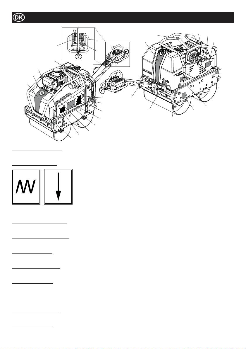
5
17
10
18
1
22
9
Delene 1 til 4 - logomærkater
Logomærkater til identi¿ cering af TDX Roller.
Del 5 – vibrationshåndtag
Mærkater
13
7
6
21
8
9
25
3
24
23
Bemærk:- illustration viser Yanmar L100N model.
20
19
2
14
9
12
4
9
16
15
Vibration
indkoblet
Del 6 – advarsler/læs manualen
ADVARSEL! Læs venligst driftsmanualen før brug af maskinen.
Del 7 – håndtag fremad/baglæns
Håndtag til ændring af maskinens retning. F = fremad, R = baglæns, Ɣ = neutral.
Del 8 - vedligeholdelse
Indikerer at hjelmen kan fjernes for indvendig vedligeholdelse.
Del 9 – fastgørelsespunkter
Indikerer hvilke områder på maskinen der kan bruges til fastgørelse for hejsning eller sænkning under transport.
Del 10 – varm overÀ ade
ADVARSEL! Vær opmærksom på varme overÀ ader omkring hydrauliktanken og udstødningsområdet.
Del 11 – motoroliens påfyldningssted
Indikerer hvor motorolien skal påfyldes, og hvor motorolieniveauet skal tjekkes.
Del 12 - hydraulikoliestand
Indikerer hydraulikoliestandsmåleren som viser hydraulikolieniveauet i tanken
Del 13 - maskinolietype
Viser, hvilke olietype der skal bruges ved påfyldning af motor.
Vibration
frakoblet
86
Page 87
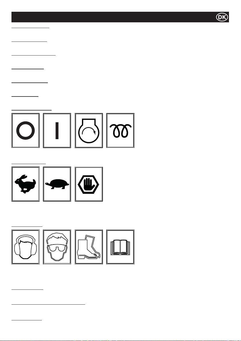
Mærkater
Del 14 – vanddræning
Hvis vejrudsigten forudser minusgrader i området, skal vandtanken drænes for vand ved brug af bundproppen.
Del 15 - håndbremse
Viser håndbremsestillingen. Håndbremsen skal være tilkoblet, når maskinen ikke er i brug.
Del 16 - sprøjtestanghane
Viser stillingen af sprøjtestanghaner samt hvilke haner, der hører til hvilke sprøjtestænger.
Del 17 – kun diesel
Motoren må KUN påfyldes diesel!
Del 18 - hydraulikolie
Placering af hydraulikolietankens påfyldningsdæksel.
Del 19 - løfteøje
Løfteøje til brug med en slynge eller mekanisk hejs.
Del 20 - tændingsnøgle
UDE INDE START
VARME
(KUBOTA)
Del 21 - gashåndtag
Maks. omdrejninger
Tomgang
Nød-
stopsstlling
pr. minut.
Del 22 - sikkerhed
Brug
høreværn
Brug
øjenværn
Brug sik-
kerhedssko
Læs
venligst
operatør-
Del 23 - støjniveau
Maskinens garanterede lydeffektniveau i dB(A).
Del 24 - varm overÀ ade (Del nr. 800-99520)
FORSIGTIG! Pas på varme overÀ ader omkring motoren og udstødning område.
Del 25 - smadring
FORSIGTIG! Pas på mekaniske komponenter, hvis afskærmningen er fjernet.
manualen
87
Page 88
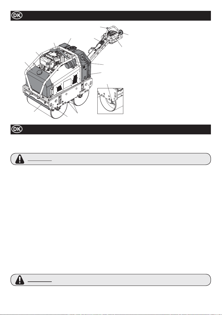
Beskrivelse af maskinen
5
1. Hydraulikolietank.
2
12
1
10
4
11
8
3
9
13
10
7
2. Løfteøje.
6
3. Luft¿ lter.
4. Vandtank.
5. Frem-/Bak-håndtag
6. Vibrationshåndtag
7. Sikkerhedshåndtag til baglæns kørsel
8. Gashåndtag
9. Vandstandsmåler
10. Skraberstænger
11. Fastgørelsespunkter.
13. Parkeringsbremse
Bemærk:- illustration viser Yanmar L100N
model.
Generelle sikkerhedsinstruktioner
For både at sikre din personlige sikkerhed og for at beskytte de personer som be¿ nder sig i nærheden af dig, er det vigtigt at du læser
og fuldt ud forstår følgende sikkerhedsinstruktioner. Der er operatørens ansvar at sikre, at han/hun fuldt ud forstår hvorledes udstyret
skal anvendes sikkert. Konsulter med din overordnede eller Altrad Belle, hvis du er i tvivl om hvordan ’TDX 650A’ Vibrationstromlen
anvendes sikkert og korrekt.
ADVARSEL
Denne maskine må kun anvendes til sit tiltænkte formål
Ɣ
Ɣ
Maskinen må kun betjenes at velskolet personale
Ɣ
Ejeren af denne maskine skal overholde de gældende arbejdsmiljøbestemmelse i det land hvor maskinen anvendes, samt
sikre, at brugeren af maskinen ligeledes er uddannet i at overholde disse regler.
Ɣ
Anvend passende løfteudstyr i forbindelse med løft af maskinen.
Ɣ
Maskinen må kun anvendes på steder hvor stabiliteten er sikret. Når maskinen anvendes nær kanten af udgravede
grøfter, skal maskinen betjenes korrekt, således at den ikke bryder sammen eller falder ned.
Hvis overÀ aden som skal komprimeres ligger på en skråning, skal der udvises stor forsigtighed i forbindelse med
Ɣ
styringen af maskinens driftsretning. Arbejd altid op og ned af skråningen, og aldrig på langs.
Afspær arbejdsområdet, og hold uvedkommende og uautoriserede personer på sikker afstand.
Ɣ
Operatøren skal bære personlige værnemidler (PVM) når maskinen anvendes (se afsnittet Helbred og Sikkerhed).
Ɣ
Ɣ
INDEN DU STARTER maskinen skal du sikre dig, at du ved hvordan maskinen sikkert SLÅS FRA, hvis du kommer i vanskeligheder.
Ɣ Motoren bliver meget varm under driften, så lad den køle af inden der røres ved den.
Forlad aldrig motoren hvis den er tændt og uden opsyn.
Ɣ
Du må aldrig fjerne eller ændre på de indbyggede sikkerhedsanordninger. De er der for din sikkerheds skyld. Kontroller altid
Ɣ
sikkerhedsanordningerne tilstand og sikkerhed. Hvis nogen af sikkerhedsanordningerne er beskadiget eller er mangelfulde
må maskinen IKKE TAGES I ANVENDELSE før disse fejl enten er repareret eller anordningerne er udskiftet.
Anvend ikke maskinen hvis du er syg, føler dig træt eller er under indÀ ydelse af alkohol eller medicin.
Ɣ
Ɣ
Denne maskine er designet med henblik på at eliminere de mulige risici som måtte kunne opstår i forbindelse med dens
anvendelse. Der ER dog risici, og de tilbageværende risici er ikke klart genkendelige, og vil kunne udgøre en kilde til
personlige kvæstelser, skade på ejendom eller dødsfald. Hvis sådanne uforudsete risici skulle opstå, skal maskinen straks
stoppes, og operatøren eller dennes overordnede skal tage de forholdsregler der er nødvendige for at eliminere faren. Det vil i
visse tilfælde være nødvendigt at informere producenten om sådanne hændelser, således at der i fremtiden kan tages
modforanstaltninger.
Brændstofsikkerhed
ADVARSEL
Ɣ Sluk motoren og lad den køle af inden påfyldning af brændstof.
Ɣ
LAD VÆRE med at ryge og tillad ikke åben ild i området under påfyldning af brændstof.
Ɣ
Spildt brændstof skal øjeblikkeligt sikres ved hjælp af sand. Hvis du spilles brændstof på tøjet, skal dette skiftes.
Ɣ
Opbevar brændstoffet i en dertil beregnet og godkendt beholder, og hold den væk fra varme- eller antændelseskilder.
Fejlagtig vedligeholdelse kan medføre fare. Læs og forstå dette afsnit inden du udfører nogen form for
vedligeholdelse, servicering eller reparationer på maskinen.
Brændstof er brændbart. Det kan medføre kvæstelser og skader på ejendom. Stop motoren, sluk al
åben ild og lad være med at ryge under påfyldning af brændstoftanken. Tør altid spildt brændstof op.
88
Page 89
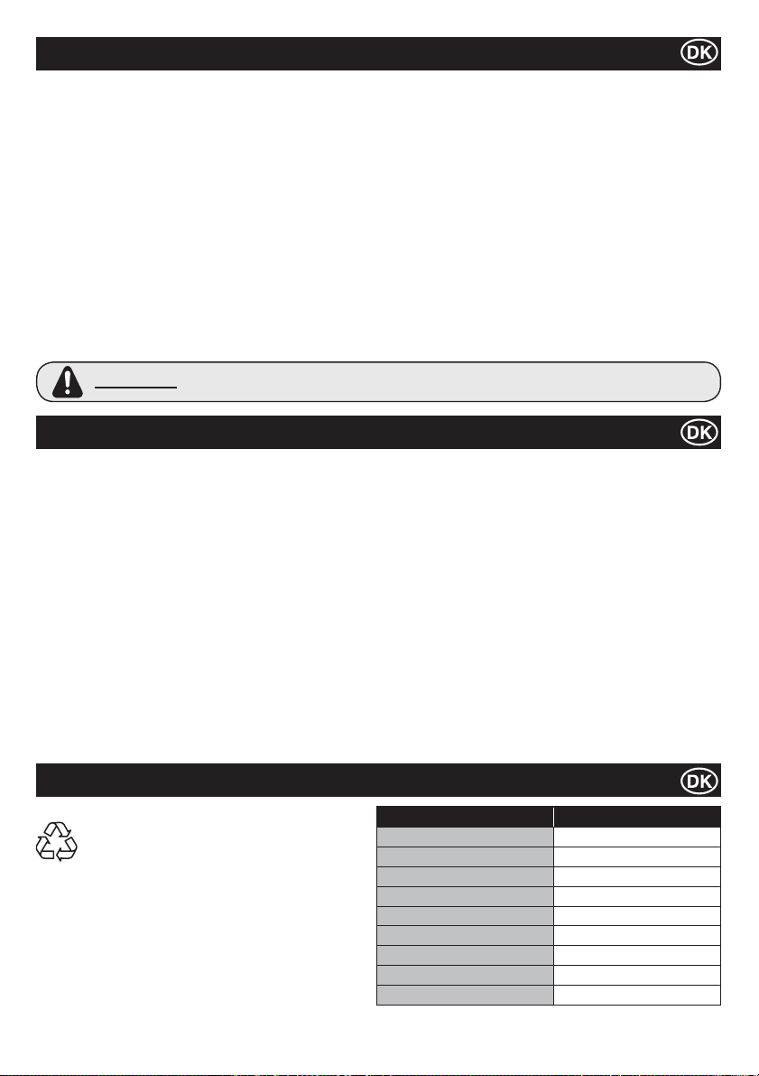
Helbred og Sikkerhed
Vibrationer.
Der vil blive transmitteret nogle vibrationer fra glittemaskinen gennem håndtaget til operatørens hænder. Altrad Belle ‘TDX 650A’ er
designet specielt med henblik på at reducere vibrationsniveauet i hænder/arme. Der henvises til afsnittet ‘Tekniske data’ for oplysninger
om vibrationsniveau og driftstid (anbefalet maksimalt daglig eksponeringstid). Overstig IKKE den maksimale eksponeringstid.
PVM (personlige værnemidler).
I forbindelse med anvendelse af udstyret skal der bæres passende PVM, såsom sikkerhedsbriller, handsker , høreværn, støvmaske
og sikkerhedssko med tåhætte af stål (med antislipsåler for øget sikkerhed). Vær passende klædt på i forhold til det arbejde du
skal udføre. Beskyt altid huden imod kontakt med beton.
Støv.
Komprimeringsprocessen kan producere støv som kan skade dit helbred. Bær derfor altid en maske, der passer i forhold til den type støv
som produceres.
Brændstof.
Brændstof eller brændstofdampe må ikke indtages eller indhaleres, og kontakt med huden skal undgås. Vask øjeblikkeligt brændstofstænk
af. Hvis du får brændstof i øjnene, skyld med rigelige mængder af vand og søg hurtigst muligt læge.
Udstødningsgasser.
Anvend ikke ‘TDX 650A’ Vibrationstromlen indendørs eller i indesluttede rum, og vær sikker på at arbejdsområdet er tilstrækkeligt ventileret.
ADVARSEL
De udstødningsgasser, som udstyret producerer, er giftige og kan være dødbringende!
Kontrol inden start
Inspektion inden opstart.
Følgende inspektion skal foretages inden opstarten, enten før hver arbejdssession eller efter ¿ re timers brug, afhængig hvilken af de
to forhold der først bliver relevant. Se venligst serviceafsnittet for detaljeret vejledning. Hvis der registreres en fejl, må ‘TDX 650A’ ikke
anvendes før denne er udbedret.
1. Undersøg maskinen grundigt for tegn på skader.
2. Kontroller slanger, påfyldningsstudser, aftapningsskruer og andre områder for tegn på utætheder. Reparer eventuelle lækager
inden arbejdet sættes i gang.
3. Kontroller olieniveauet i motoren, og påfyld, hvis der er nødvendigt.
3-1. Placér maskinen op en plan overÀ ade, og kontroller olieniveauet i motoren.
3-2. Fjern oliestandsglasset og læg mærke til om olieniveauet når op til kanten af påfyldningsåbningen. Anvend egnet motorolie med
passende viskositet (Se venligst SAE serviceklasse viskositetsskema i serviceringsafsnittet).
4. Kontroller brændstofniveauet i motoren, og fyld på, hvis der er nødvendigt. Anvend rent brændstof. Brug af urent brændstof kan
skade brændstofsystemet.
5. Kontroller at luft¿ lteret er rent.
Overdreven ophobning af snavs/støv i ¿ lterelementet vil medføre uregelmæssig motorgang. Rens luft¿ lterelementet hvis det
er beskidt (se vedligeholdelsesafsnittet).
6. Kontroller at styreenhederne fungerer.
Kontroller at kørehåndtaget, vibrationshåndtaget, gashåndtaget, parkeringshåndtaget samt sikkerhedsanordningen for bagudrettet
kørsel bevæger sig let.
7. Kontroller kølervæskestanden. Top op til niveau ‘fylde’, hvis det kræves - KUBOTA KUN!
Miljø
Sikker bortskaffelse
Vejledninger i forbindelse med beskyttelse af miljøet.
Maskinen indeholder værdifulde materialer. AÀ ever det
kasserede apparat og tilbehør på en relevant
genbrugsstation.
Komponent Materiale
Betjeningshåndtag Stål
Hovedchassis Stål
Hydraulisk olietank Stål
Vandtank Polyethylen
Dæksel Polyethylen
Hydraulisk pumpe Stål og aluminium
Hydraulisk Motor Stål
Motor Stål og aluminium
Diverse dele Stål, aluminium og gummi
89
Page 90
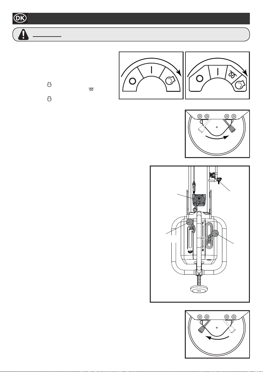
Start-/Standsningsprocedure
ADVARSEL
Inden du starter motoren, skal du sikre dig, at kørehåndtaget er indstillet på Neutral, at vibrationshåndtaget er sat på OFF samt at
parkeringshåndtaget står i ON position.
1. Åbn motorens brændstofhane.
2. Stil betjeningsgrebets gashåndtag til fuld gas-stilling.
Start motoren – elektrisk start
3ai. YANMAR - Drej gashåndtagets nøglekontakt til
stillingen Start
3aii. KUBOTA - Fra cool, holde på varmen position i 10
sekunder. Drej gashåndtagets nøglekontakt til
stillingen Start
Man MÅ IKKE dreje i længere periode. Maksimalt 10 sekunder.
3b. Efter at motoren er startet, sørg for at nøglen sidder i stillingen ON/inde (I) under driften.
(Hvis nøglen stilles til stillingen OFF/ude (0), kan generatoren ikke lade batteriet.)
Start motoren – manuel start
4a. Tag fat i trækstarterhåndtaget.
4b. Træk håndtaget langsomt indtil der mærkes stærk modstand.
4c. Bring trækstarterhåndtaget tilbage til den oprindelige stilling.
4d. Skub dekompressionshåndtaget ned og derefter slip den. Dekompressionshåndtaget vil
automatisk vende tilbage til den oprindelige stilling når motoren starter.
4e. Tag fat i trækstarterhåndtaget.
4f. Træk håndtaget hele vejen ud med en kraftig og jævn bevægelse. Brug to hænder hvis det
er nødvendigt.
4g. Før starthåndtaget langsomt tilbage til den oprindelige stilling.
4h. Hvis motorren ikke starter, gentag proceduren fra trin 4b.
5. Bevæg gashåndtaget til stillingen LOW/lav og lad motoren køre i
tomgang nogle minutter for at opvarme den.
6. Maskinen er driftsparat, når motoren er varmet op.
7. Bevæg gashåndtaget til stillingen af hurtig hastighed, “H”, for at
forhindre skaden på koblingen. “Fuld gas”-stillingen er forudindstillet fra
fabrikken for at opnå maskinens optimale ydeevne.
Denne stilling MÅ IKKE ændres, da tidlig slitage kan medføre at både
motorens og maskinens garanti automatisk annulleres.
8. Bevæg håndbremsen til højre for at frigøre den.
BEMÆRK: Hvis man ikke frakobler håndbremsen, før man forsøger at køre
maskinen fremad eller baglæns, vil det forårsage alvorlige
skader på bremsemekanismen samt driftssystemet.
9. Operatørstyring
9a. Gashåndtag
Hold altid gashåndtaget på høj stilling under arbejde. Man MÅ IKKE
ændre kørehastigheden ved at ændre motorens omdrejninger.
9b. Kørehåndtag
Skub kørehåndtaget fremad for at drive maskinen fremad. For at
bevæge maskinen baglæns, skub håndtaget baglæns.
9c. Vibrationshåndtag
Ved at À ytte vibrationshåndtaget til stillingen ON/inde, kobles
vibrationsmekanismen ind og starter at producere vibration.
10. Standsning af motoren
11. For at forberede standsning af motoren, À yt gashåndaget til stillingen
LOW/lav.
12. Lad maskinen køre i tomgang i 1-3 minutter.
13. Flyt gashåndtaget til stillingen STOP for at stoppe motoren. Stil
derefter nøglekontakten til stillingen “OFF”/ude. Summeren lyder, når
nøglekontakten er sat til ON/inde og motoren er stoppet.
14. Luk brændstofhanen
15. Træk håndbremsen ved at svinge håndbremsehåndtaget til venstre.
Fejlagtig vedligeholdelse kan medføre fare. Læs og forstå dette afsnit inden du udfører nogen
former for vedligeholdelse, service eller reparationer.
YANMAR KUBOTA
og hold den indtil motoren starter.
og hold den indtil motoren starter.
FRAKOBLING
GASHÅNDTAG
VIBRATION-
SHÅNDTAG
NØGLE-
KONTAKT
KØRE-
HÅNDTAG
90
INDKOBLING
Page 91

Betjening af TDX 650A-Vibrationstromler
Ɣ Efter at have udført kontrollerne beskrevet i afsnittet “Kontrol inden start” kan du starte maskinen.
De Håndstyrede Vibrationstromler i TDX 650A serien fra Altrad Belle er udstyret med en centrifugalkobling, hvilket tillader at
motoren kører i tomgang uden at den Hydrauliske pumpe samtidt kører.
Når motorhastigheden forøges, vil koblingen blive aktiveret og motoren vil drive den Hydrauliske pumpe for at sende hydraulisk
Ɣ
kraft til tromlerne såvel som til vibrationsmekanismen. For at undgå skader på centrifugalkoblingen skal gashåndtaget À yttes
hurtigt fra position L til position H. Hastigheden skal, ved korrekt betjening, sættes til maksimum under udførelse af
komprimeringsarbejder.
Ɣ
Undlad at anvende maskinen på fuldt komprimerede, hårde og ikke-eftergivende overÀ ader. I modsat fald vil ophænget og
øvrige mekaniske komponenter blive skadede og maskinens levetid voldsomt reduceret.
Ɣ
Ved arbejde på en stejl skråning, vær særlig opmærksom på at maskinen ikke ruller ned ad skråningen.
Arbejd altid op eller ned ad skråningen. Arbejd ikke på tværs af skråningen. Når maskinen er parkeret på skråningen, skal
håndbremsen altid være tilkoblet.
Ɣ
Det er vigtigt at man ikke står bagved maskinen når den kører baglæns. Gå altid i førerstangens retning med hovedet i
kørselsretningen.
Løftning
Ɣ
Hvis man skal bruge løfteudstyr til at anbringe TDX 650A et sted, sørg da for at løfteudstyrets løftekapacitet er tilpasset til
maskinens vægt (se tabellet med tekniske data). Fastgør KUN passende kæder eller slynger på de dertil beregnede løftepunkter på
maskinens midte (løfteøje) eller i maskinens hjørner (løftepunkter).
TRANSPORT
Ɣ
Transport på et køretøj.
Vær sikker på at håndtaget er låst, og anvend passende ramper med tilstrækkelig bredde, længde og styrke ved både
læsning og aÀ æsning.
Aktivér parkeringsbremsen, og sur maskinen forsvarligt fast til køretøjet under transport.
Ɣ
Service
Vedligeholdelse
Den håndstyrede Vibrationstromle i TDX 650A-Serie fra Altrad Belle er designet til at kunne fungere problemfrit i mange år. Der er
imidlertid vigtigt, at den simple regelmæssige vedligeholdelsesrutiner bliver udført, som beskrevet i dette afsnit. Det anbefales at lade
alle større vedligeholdelses- og reparationsarbejder udføres af en godkendt Altrad Belle forhandler. Anvend altid originale Altrad Belle
reservedele. Anvendes altid originale reservedele, da ukorrente reservedele kan medføre at garantien ikke længere vil være gældende.
Før enhver vedligeholdelse på maskinen, sluk motoren og fjern nøglen fra nøglekontakten.
Placer altid maskinen på en plan grund, således at det sikres at alle væskeniveauer kan aÀ æses korrekt. Anvend kun anbefalede
olietyper (se skemaet på næste side).
Servicering af motoren
Udfør service på motoren i henhold til de af motorfabrikanten afgivne speci¿ kationer.
Der henvises til motorens drifts- og vedligeholdelsesmanual.
Bemærk: Når vedligeholdelsesdækslet er fjernet, sørg for at alle bolte spændes godt fast ved genmontering. Man MÅ IKKE
genstarte maskinen, når afskærmningerne er fjernet.
Vedligeholdelse: Hver 8. time eller dagligt
1. Kontroller om der er løse bolte eller møtrikker. Stram hvis nødvendigt.
2. Kontroller og rengør luft¿ lterelementet, smør elementet i henhold til maskinproducentens anbefalinger. Hvis driftsforholdene er
usædvanlig støvede eller hårde skal rensningen af ¿ lterelementet foretages oftere.
91
Page 92
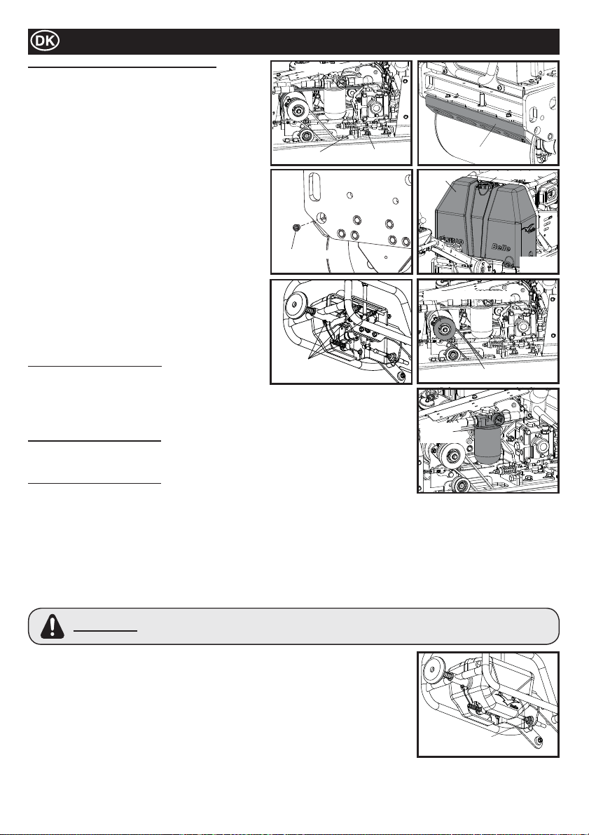
Service
Vedligeholdelse: Hver 50. time eller ugentligt
1. Kontroller spændingen på kileremmen
1a. Løsn de ¿ re bolte der fastholder pumpebeslaget, og skru
justeringsbolten indtil den rette spænding opnås.
Remmen skal give sig ca. 5 mm på midten mellem
centrifugalkoblingen og pumpehjulet.
1b. Stam de ¿ re bolte på pumpebeslaget. Hvis kileremmen
er udtjent eller revnet skal den udskiftes.
2. Tilpasning af mellemrummet på skraberen
2a. Fjern skraberen, og borttag alt smuds, mudder, og asfalt.
2b. Genmonter skraberen på skraberbeslaget, og fastgør
det med en passende frigang i forhold til tromlen.
3. Vandtank
3a. Dræn alt vandet og rengør inderside af tanken ved
hjælp af en slange.
4. Sprinklerdyse
4a. Fjern dækslet fra dysen, og rengør indersiden af
sprinklerdysen.
5. Bevægelige dele
5a. Tilfør smørelse til køre-/vibrationskablets
stempelstangsende.
5b. Gensmør smørepunkterne i betjeningshåndtaget.
5c. Smør vibrator aksel
Vedligeholdelse: Hver 100 timer
1. Vibrationskoblingsmekanismen
1a. Kontroller vibrationskoblingsmekanismen for at sikre, at
den fungerer som den skal.
1b. Tilfør smørelse til de bevægelige dele.
1c. Kontroller kileremmens tilstand. Hvis kileremmen er udslidt eller revnet skal den udskiftes.
Vedligeholdelse: Hver 500. time
1. Udskift det hydrauliske olie¿ lterelement for hver 500 driftstimer.
Anvend originale ¿ lterelementer.
Vedligeholdelse: Hver 800. time
1. Udskift den hydrauliske olie.
Gennemskyld tanken inden den nye hydrauliske olie påfyldes.
Lad tankdækslet stå åbent, og lad motoren køre på maksimal hastighed i ti minutter,
uden at benytte køre- eller vibrationshåndtaget, for derved at ventilere det hydrauliske system.
TILPASNING AF KØREHÅNDTAGETS NEUTRALE INDSTILLING
Kørehåndtagets neutrale indstilling kan À ytte sig som følge af vibrationerne eller slid på drivkablerne. Følg nedenstående procedure for
at tilpasse ned neutrale indstilling:
1. Placer maskinen på en plan overÀ ade.
2. Kontroller at motoren er slukket.
3. Fjern møtrikken som ¿ kserer stempelstangsenden på drivkablet til kørehåndtaget.
Forsøg ikke at starte motoren medens møtrikken er fjernet. Maskinen kan foretage pludselige og
ADVARSEL
4. Løsn låsemøtrikken på stempelstangsenden.
5. Drej stempelstangsenden enten med eller mod uret afhængigt af retningen af den neutrale
position.
6. Genmonter stempelstangsenden til kørewiren, og fastgør den med møtrikken.
7. Start motoren, og forøg motorens omløbshastighed indtil maksimum. Læg mærke til om den
neutrale position er rigtigt indstillet.
8. Hvis ikke, stands motoren, og gentag proceduren i punkt 5 til 7 indtil den neutrale position er
rigtigt indstillet.
9. Når den neutrale position er rigtigt indstillet, påsmøres der Loctite på møtrikken, hvilket
¿ kserer stempelstangsenden og stammer den. Herefter strammes låsemøtrikken på
stempelstangsenden.
uforudsigelige bevægelser uden at man har mulighed for at styre den via kørehåndtaget. Dette kan føre til
alvorlige kvæstelser og skader på ejendom.
DRIVREM
REMSTRAMMER
SPRINKLERDYSEN
SMØRE-
PUNKTERNE
KONSOLBOLTER
SCRAPER
TANK
VIBRATIONSKOBLINGS
KILEREMMEN
FILTER
ELEMENT
LÅSEMØTRIK
DÆKSLET
DRÆN-
PROP
92
Page 93
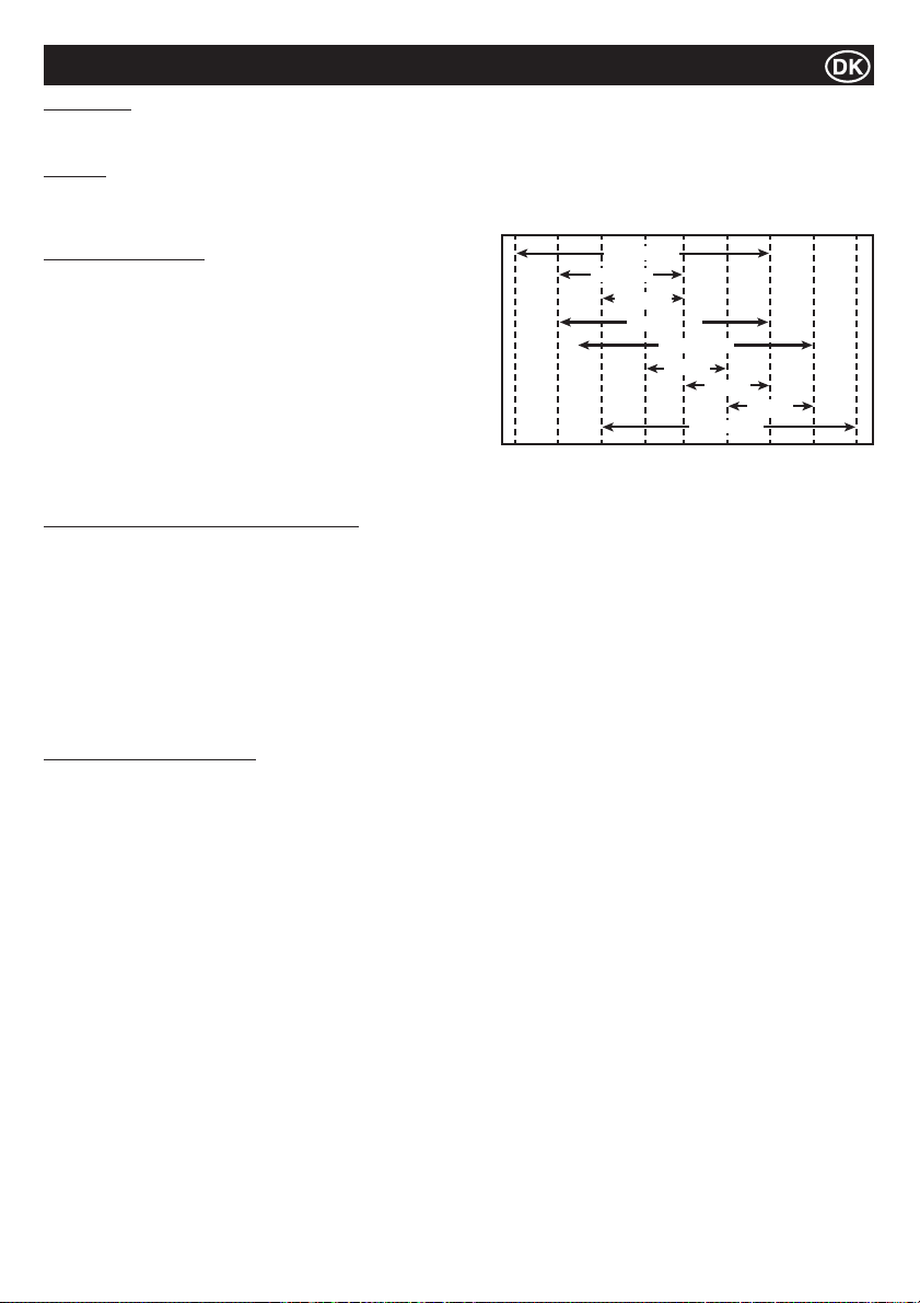
Service
Hydraulikolie
Ɣ Total EP32, Shell Tellus T37, MOBIL DTE15 or ESSO Unipower, XL46.
Motorolie
Vælg den korrekte motorolieviskositet baseret på den omgivende temperatur og brug SAE serviceklasse viskositetsskemaet nedenfor.
Denne maskine er påfyldt SAE 15W-40 fra fabrikken
-4°F
SAE 10W
14°F
(-10°C)
SAE 5W-30
SAE 20W
SAE 10W-30
32°F
(0°C)
SAE 15W-40
SAE 20
SAE 30
SAE 20W-50
50°F
68°F
(10°C)
(20°C)
SAE 40
86°F
(30°C)
104°F
(40°C)
122°F
(50°C)
Motoroliespeci¿ kationer
Brug en motorolie, der opfylder eller overstiger følgende retningslinjer
og klassi¿ kationer:
Servicekategorier
Ɣ API servicekategorier CD eller højere.
Ɣ ACEA servicekategorier E-3, E-4 og E-5
Ɣ JASO servicekategorier DH-1
De¿ nitioner
Ɣ API klassi¿ kation (American Petroleum Institute)
Ɣ ACEA klassi¿ kation (Association des Constructeurs
Européens d’automobilies)
Ɣ JASO (Japanese Automobile Standards Organisation)
30°F
(22°C)
(-20°C)
Procedure for udskiftning af motorolie - Yanmar
1. Sørg for, at køretøjet er på en plan overÀ ade og betjeningshåndtaget er i opbevaringspositionen. Træk håndbremsen.
2. Løsn bolten på undersiden af olietanken/bundprop. ADVARSEL:- Fjern IKKE bolten på dette tidspunkt.
3. Skub slangen fra sidepanelet.
4. Fjern 4 x M8 stilleskruer med en 13 mm skruenøgle. Fjern sidepanel.
5. Tag slangen ud af kabinettet, fjern proppen og tøm olien ud i en beholder.
6. Fastgør sidepanelet med en 13 mm skruenøgle, og skub oliepåfyldning/aÀ øbsslangen tilbage i åbningen i panelet. Spænd
møtrikken for at sikre at sidepanelet men sæt ikke proppen i.
7. Hæld olie i påfyldningsslangen gennem en tragt. Der skal udvises forsigtighed mens påfyldning sker for at sikre at kapaciteten ikke
overskrides. Brug målepind på venstre side af motoren for at kontrollere oliestanden.
8. Isæt oliepåfyldnings-/bundprop igen.
9. Kontroller at maskinen fungerer korrekt.
Procedure for batteriudskiftning
1. Fjern de ¿ re bolte fra sideafskærmningen ved hjælp af en 13mm skruenøgle, og fjern sideafskærmningen. Gem fastgørelsesdelene.
2. Ved hjælp af en 11 mm skruenøgle, fjern jordkablet fra batteriet og fjern positivkabelet fra batteriet.
3. Fjern batteriklemme og underlag. Fjern de to møtrikker og de to spændskiver med en 13 mm skruenøgle.
4. Fjern lang batteritap og -skive med en 13 mm skruenøgle.
5. Fjern de to bolte fra fordeleren med en 10 mm skruenøgle.
6. Fjern beslaget som var bag fordeleren med en 10 mm nøgle. Sørg for ikke at miste afstandsstykket bag beslaget.
7. Flyt det À eksible kabel ved at fastholde rem og træk ledningerne ud.
8. Skyd batteriet ud ag erstat det med det nye batteri.
9. Monter ledningerne på plads igen, og sikr deres placeringer med kabelfastholder.
10. Sæt beslaget og afstandsstykke på, og spænd til 12Nm.
11. Sæt de to bolte i fordeleren, og spænd til 12 Nm.
12. Montér batteritap og -skive, og stram til 28 Nm.
13. Montér batteriklemme og -underlag ved hjælp af en 13 mm fastnøgle. Spænd møtrikken for at sikre, at 8 mm gevind er synligt.
14. Fastgør positivkablet til batteriet efterfulgt af jordkablet.
15. Montér sidebeskytteren. Spænd de ¿ re bolte til 28 Nm.
93
Page 94
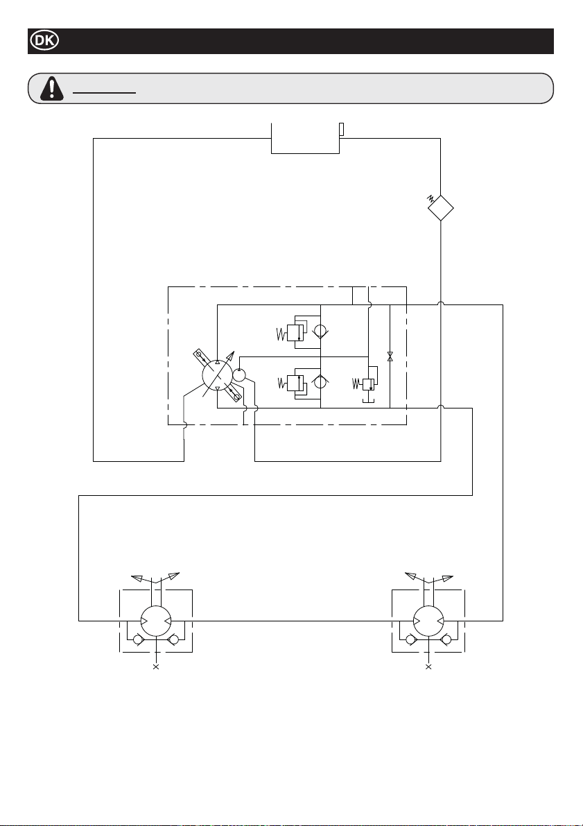
Hydraulisk Circuit
ADVARSEL
Når der udføres reparationer på det hydrauliske system, skal proppen til tanken løsnes, så det sikres,
at der ikke er tryk på systemet.
94
Page 95
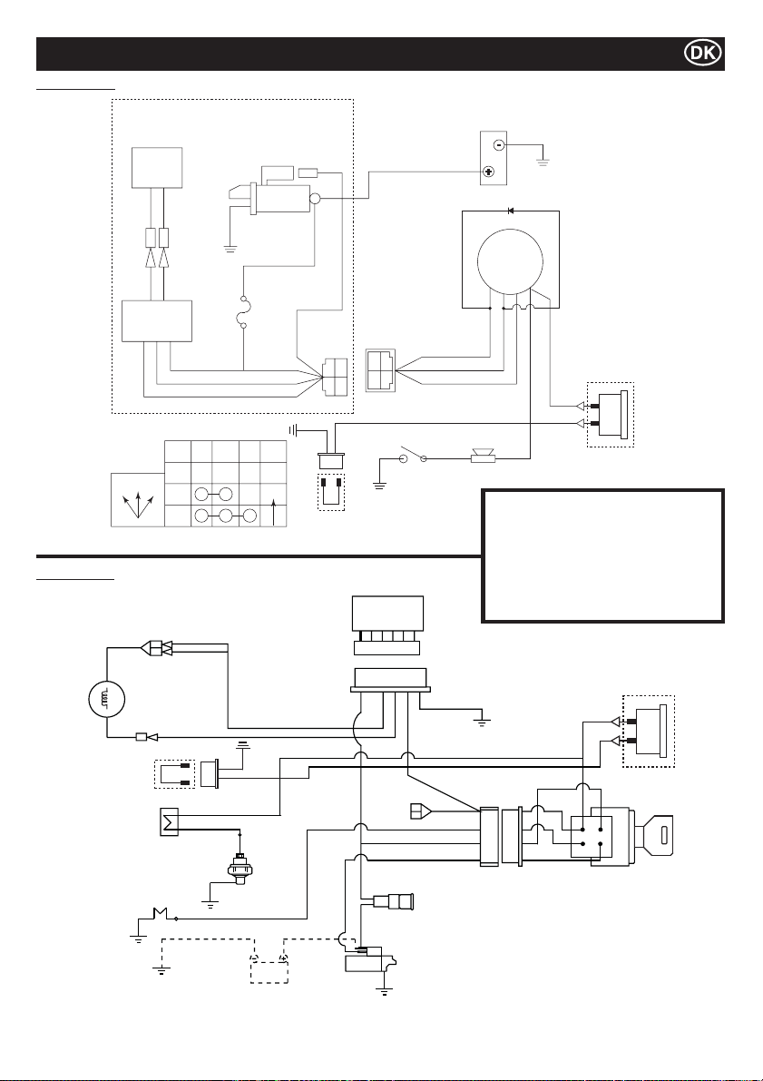
Yanmar L100N
Ledningsdiagram
Kubota EA330
12V - 15A
Dynamo
G/W G/W
CB104 CB104
CA104 CA104
G/W G/W
Regulator
SÅDAN VIRKER NØGLEKONTAKTEN
IG BAT ST NOTE
SLUK
SLUK12
1
2
Y
Startmotor
DC12v 0.8Kw
W
JAS0
D601
20T
W
G
Y
AUTO
M8
Skrue
R
YAZAKI NO.
7323-2446
B
B
Timers ur
Lænke Tråd
R
Y
G
W
BR
YAZAKI NO.
7322-2446
R
WG
Olietrykkontakt
Jord
Regulator
SBGBK
R
SB
AV2 0
AV1 .25
AV1 .25
AV1 .25
AV2 0
IG
(15)
G
R
W
Sirene
Diode
Nøglekontakt
BAT
(30)
ST
(50)
Jord
(batteri)
(25)
Y
Y
Timers ur
Option
Inventaris
G = Grøn IG = Tænding
W = Hvid BAT = Batteri
Y = Gul ST = Start
R = Rød BK = Sort
BL = Blå SB = Himmelblå
OR = Appelsin BR = Brun
Y
Ventilatordynamo
Timers ur
Lænke Tråd
R
B
Sirene
Oliekontakt
Gløderør
BK/R
SB
BK
Y
BR
Batteri
BR
BR
Y
Y
R
Y
Y
W
W
BK/R
R
BK/W
Y
G
R
Timers ur
Option
Startskontakt
R
Lunte
Starten
95
Page 96
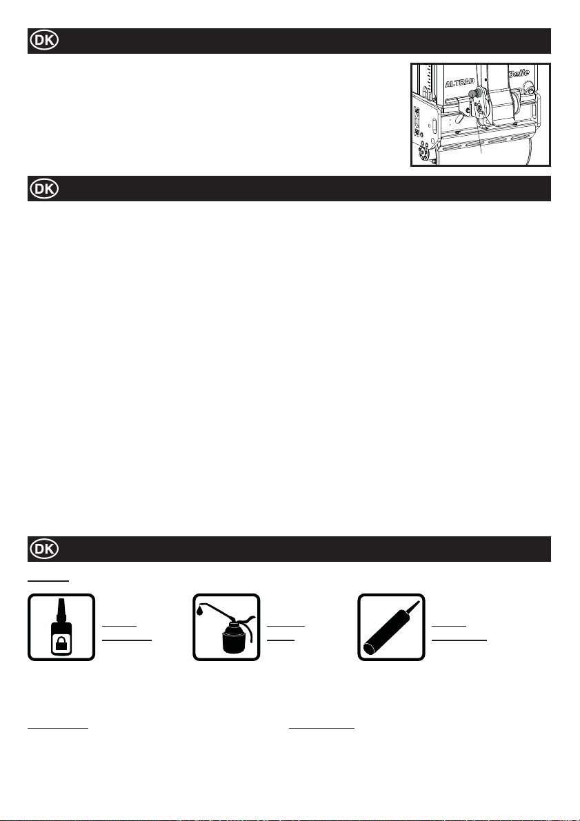
Længerevarende opmagasinering
1. I forbindelse med længerevarende opmagasinering skal Brændstoftanken tømmes ved
enten at suge den tilbageværende brændstof ud gennem Indløbsporten eller gennem
brændstof¿ lteret efter at brændstofkoppen er fjernet.
2. Rens Luft¿ lterelementet.
3. Fjern olie- og støvansamlinger fra alle gummidele.
4. Rengør baseplade og påfør en tynd hinde af olie for at forhindre rustdannelse.
5. Overdæk maskinen og opmagasiner den på et tørt sted.
6. Styrehåndtaget kan holdes oprejst under opmagasineringen. Træk i stopperen, og hæv
håndtaget. Kontroller at Stopperen holder Styrehåndtaget forsvarligt.
GRENDEL
Garanti
Din nye Altrad Belle TDX 650A Vibrationstromle er omfattet af en garanti i forhold til den oprindelige køber, gældende i ét år (12
måneder) gældende fra købsdatoen.
Altrad Belle garantien dækker konstruktionsfejl, materialefejl samt fejl i forbindelse med den håndværksmæssige udførelse. Følgende
er ikke dækket at Altrad Belle garantien:
1. Skader som følger af misbrug, forkert anvendelse, tab eller andre lignende skader som følge af, eller som er et resultat af,
manglende overholdelse af samle-, drifts- eller brugervedligeholdelsesinstruktionerne.
2. Ændringer, tilføjelser eller reparationer der er udført af personer uden forbindelse med Altrad Belle eller dennes anerkendte
repræsentanter.
3. Udgifter til transport eller forsendelse til og fra Altrad Belle eller dennes anerkendte repræsentanter i forbindelse med
reparationer eller vurdering af garantikrav for hvilken som helst maskine.
4. Materialer og/eller arbejdsomkostninger i forbindelse med fornyelse, reparation eller udskiftning af komponenter som følge af
almindelig slitage.
De følgende komponenter er ikke dækket af garantien:
- Luft¿ lter til motor
Altrad Belle og/eller dennes anerkendte repræsentanter, direktører, ansatte eller assurandører vil ikke kunne holdes ansvarlige for
indirekte skader eller andre skader, tab eller udgifter i relation til, eller som følge af, eller manglende evne til at anvende maskinen til et
hvilket som helst formål.
Garantikrav
Alle garantikrav skal i første instans stiles til Altrad Belle, enten per telefon, via fax, e-mail, eller brev.
Ved garantikrav:
Altrad Belle Warranty Department,
Sheen, Nr. Buxton,
Derbyshire SK17 0EU, England.
Oplysninger om reservedele
NØGLE
BRUG
LOCTITE
Oplysninger vedrørende maskinens reservedele og deres tilgængelighed kan ¿ ndes på www.Belle247.com eller fås ved at kontakte
ALTRAD Belle, der har følgende kontaktoplysninger:-
# - Farvevalg 1 ## - Farvevalg 2
Vare nr. + S = Orange (Eg. 981/05100S) Vare nr. + GR = grå (Eg. 981/03200GR)
Vare nr. + G = grøn Vare nr. + GR2 = kvartsgrå
Vare nr. + B1 = blå Vare nr. + BL = sort
Vare nr. + R1 = rød Vare nr. + W = hvid
Vare nr. + Y = gul
Vare nr. + Y2 = gul
BRUG
OLIE
96
ILICONE
S
BRUG
SILICONE
Page 97
Verwendung dieses Handbuches
Dieses Handbuch wurde verfasst, um Sie beim sicheren Betrieb und Service der Walze TDX 650A zu unterstützen. Es ist für Händler
und Anwender der Walze TDX 650A gedacht.
Vorwort
Der Abschnitt ‘Beschreibung der Maschine’ macht Sie mit dem Aufbau und den Steuerelementen der Maschine bekannt.
Der Abschnitt ‘Umwelt’ enthält Anweisungen für ein umweltfreundliches Recycling von ausrangierten Maschinen.
Die Abschnitte ‘Sicherheitshinweise sowie Gesundheit’ und ‘Sicherheit’ erklären den Betrieb der Maschine im Hinblick auf Ihre
Sicherheit und die Sicherheit anderer Personen.
Der Abschnitt ‘Betriebsanleitung’ hilft Ihnen beim Aufbau und beim Einsatz der Maschine.
Der Abschnitt ‘Finden und Beseitigen’ von Störungen hilft Ihnen, wenn Sie Probleme mit Ihrer Maschine haben.
Der Abschnitt ‘Wartung und Instandhaltung’ hilft Ihnen bei allgemeinen Wartungs- und Reparaturarbeiten an Ihrer Maschine.
Hinweise zur Schreibweise
VORSICHT
WARNUNG
Für das Produkt kann eine Gefahr darstellen. Bei unsachgemäßem Umgang kann die Maschine
beschädigt werden und Personen können zu Schaden kommen.
Für die bedienende Person kann Lebensgefahr bestehen.
WARNUNG
WARNUNG
INFROMIEREN Sie sich gründlich über die sachgemäße Betätigung der Bedienelemente an dieser Maschine und über die gefahrlose
Durchführung von Wartungsarbeiten.
(NB! Sorgen Sie dafür, dass Sie vor dem Einschalten der Maschine wissen, wie die Maschine ausgeschaltet wird – für den Fall, dass
Sie Schwierigkeiten mit der Maschine haben sollten.)
Verwenden Sie IMMER die für Ihren persönlichen Schutz erforderliche Sicherheitsausrüstung.
Sollten Sie FRAGEN zum sicheren Betrieb und zur Wartung dieser Maschine haben, WENDEN SIE SICH AN IHREN VORGESETZTEN ODER DIE Altrad Belle. Tel: +44 (0)1298 84606
Bevor Sie diese Maschine in Betrieb nehmen oder Wartungsarbeiten an ihr durchführen, MÜSSEN
SIE dieses Handbuch GRÜNDLICH STUDIEREN.
Inhalt
Verwendung dieses Handbuches .............................................................................................................................................................97
Warnung ...................................................................................................................................................................................................97
Technische Daten ..................................................................................................................................................................................... 98
Aufkleber .........................................................................................................................................................................................99 - 100
Beschreibung der Maschine ................................................................................................................................................................... 101
Sicherheitshinweise ................................................................................................................................................................................101
Gesundheit und Sicherheit .....................................................................................................................................................................102
Kontrolle vor dem Einsatz ...................................................................................................................................................................... 102
Umwelt .................................................................................................................................................................................................... 102
Inbetriebnahme und Abstellen der Maschine ......................................................................................................................................... 103
Bedienung der Walze TDX 650A............................................................................................................................................................ 104
Wartung und Instandhaltung ......................................................................................................................................................... 104 - 106
Hydraulikkreis .........................................................................................................................................................................................107
Schaltplan ...............................................................................................................................................................................................108
Einlagerung der Maschine......................................................................................................................................................................109
Garantie ..................................................................................................................................................................................................109
Information zu den Ersatzteilen .............................................................................................................................................................. 109
Konformitätserklärung ................................................................................................................................................................................3
Die Altrad Belle behält sich das Recht vor, jederzeit an der Maschine ohne vorherige Ankündigung technische Veränderungen vorzunehmen.
97
Page 98

Technische Daten
J
B
G
D
A
Modell TDX 650A Yanmar L100N TDX 650A Kubota EA330
Gewicht* - Kg 675 684
A - Gesamtlänge - mm 2318 2318
B - Gesamthöhe- mm 1137 1137
C - Radstand - mm 560 560
D - Walzendurchmesser - mm 402 402
E - Walzenbreite - mm 650 650
F - Gesamtbreite - mm 703 703
G - Kantenfreiheit - mm 258 258
H - Seitenüberhang - mm 26.5 26.5
J - Einlagerungshöhe - mm 1678 1678
Fahrgeschwindigkeit (vorwärts) - m/m (km/h)
Fahrgeschwindigkeit (rückwärts) - m/m (km/h)
Frequenz - v.p.m 3300 3300
Zentrifugalkraft - kN 16 16
Kapazität des Wassertanks - Ltr 65 65
Kapazität des Öltanks - Ltr 16 16
Motor YANMAR L100N KUBOTA EA330
Typ Viertaktmotor, Luftgekühlt Viertaktmotor, Wassergekühlte
Treibstoff Diesel Diesel
Kapazität des Treibstofftanks - Liter 5.4 4.8
Arbeitsleistung - Hp (kW) 9 (6.6) 5.9 (4.4)
Höchstleistung - Hp (kW) 10 (7.4) 6.9 (5.2)
Anlasser
* Das Gewicht ist ohne Wasser im Wassertank. Wasser im Tank = 65 Liter = 65 kg
Elektrisch (mit Recoil Anfang Back-up-Option)
0 - 70 (0 - 4.2) 0 - 70 (0 - 4.2)
0 - 38 (0 - 2.3) 0 - 38 (0 - 2.3)
C
H
E
F
Elektrisch
98
Page 99
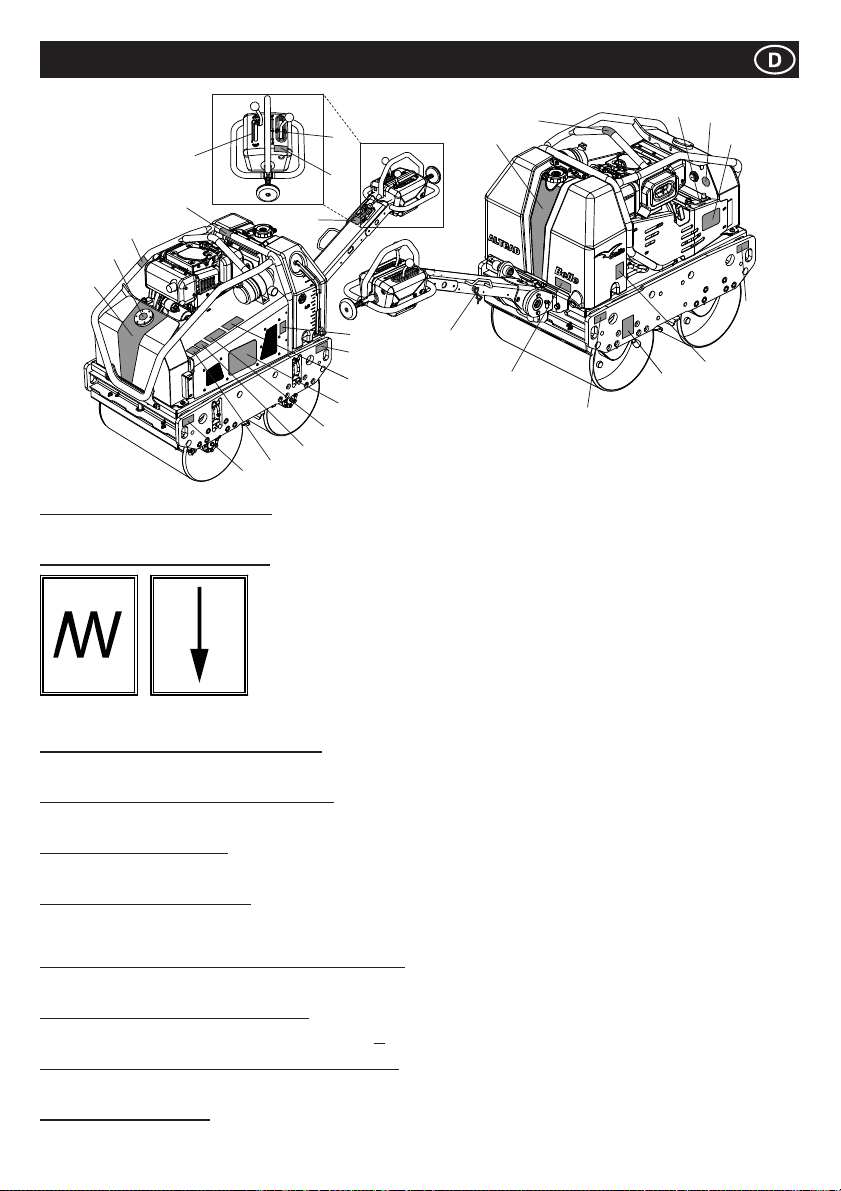
7
5
17
10
18
1
22
9
Elemente 1 bis 4 – Branding-Aufkleber
Branding-Aufkleber zur Identi¿ zierung des TDX Rollers.
Element 5 – Aufkleber Vibrationshebel
6
21
24
23
Aufkleber
19
2
8
9
25
3
Hinweis:- Illustration zeigt die Yanmar L100N-Modell.
20
14
9
13
12
4
9
16
15
Vibration
Feststellen
Element 6 - Aufkleber Achtung/Anleitung lesen
ACHTUNG! Bitte lesen Sie vor der Inbetriebnahme der Maschine das Bedienungshandbuch!
Element 7 – Aufkleber Vorwärts-/Rückwärtshebel
Hebel für Richtungsänderungen der Maschine. V = Vorwärts, R = Rückwärts, Ɣ = Neutral.
Element 8 – Wartungsaufkleber
Zeigt an, dass die Abdeckung für innere Wartungszwecke entfernt werden kann.
Element 9 – Befestigungsaufkleber
Zeigt an, welche Teile der Maschine zum Befestigen an einer Hebevorrichtung für das Hochheben der Maschine und zur Sicherung
während des Transports benutzt werden können.
Element 10 – Aufkleber zur Warnung vor heißen OberÀ ächen
VORSICHT! Achten Sie auf heiße OberÀ ächen rund um den Hydrauliktank und im Bereich des Auspuffs.
Element 11 – Aufkleber für Motoröleinfüllung
Zeigt an, wo Sie Motoröl nachfüllen und kontrollieren können.
Element 12 – Aufkleber zur Anzeige des Hydraulikölstandes
Zeigt die Position des Hydraulikölpegels, der den Hydraulikölstand im Tank anzeigt.
Element 13 – Öltypaufkleber
Erklärt, welche Art von Öl für den Motor benutzt werden soll.
Vibration
Lösen
99
Page 100
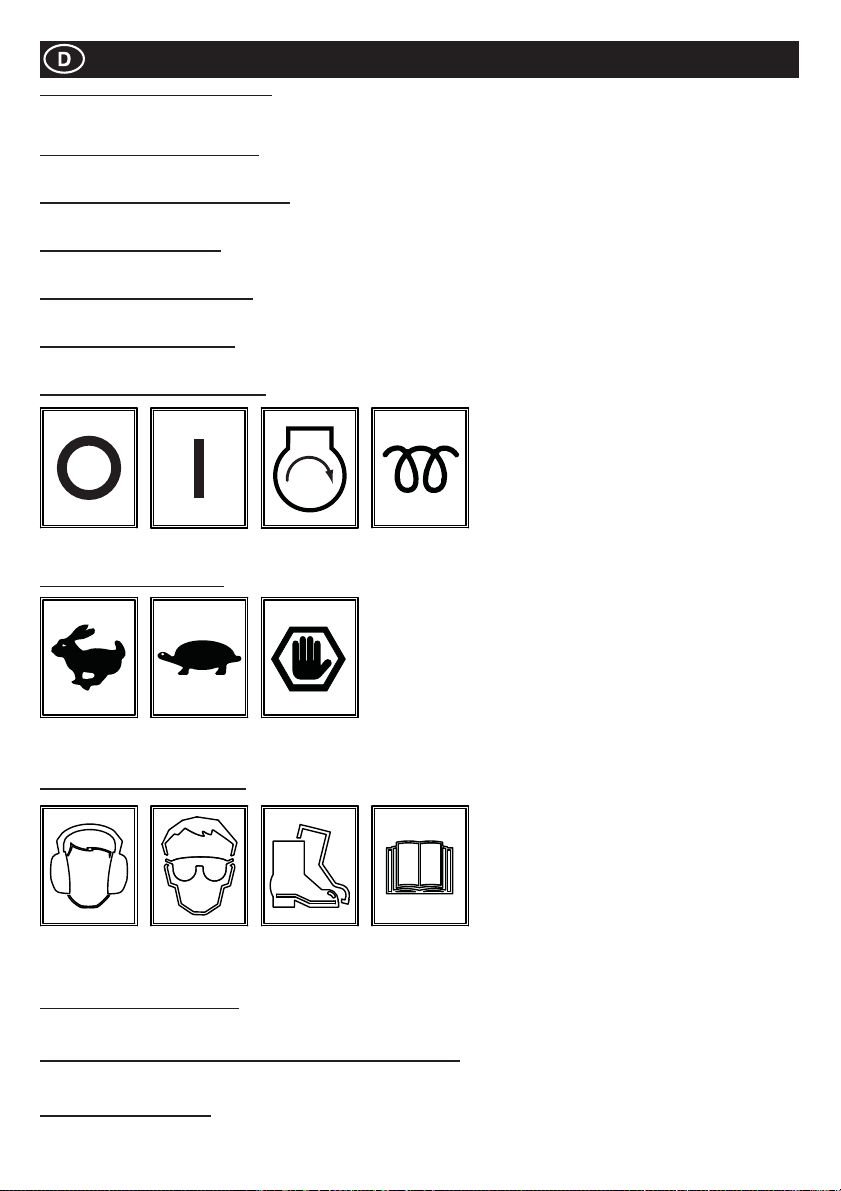
Aufkleber
Element 14 – Aufkleber WasserabÀ uss
Falls die vorausgesagte Umgebungstemperatur unter den Gefrierpunkt fällt, muss der Wassertank mittels Ablassschraube entleert
werden.
Element 15 – Aufkleber Handbremse
Zeigt die Position der Handbremse. Wenn die Maschine nicht in Betrieb ist, muss die Handbremse angezogen werden.
Element 16 – Aufkleber Sprühleistenhahn
Zeigt die Position der Sprühleistenhähne und welcher Hahn zu welcher Sprühleiste gehört.
Element 17 – Diesel-Aufkleber
Der Motor darf NUR mit Diesel betrieben werden!
Element 18 – Hydrauliköl-Aufkleber
Zeigt die Position des Hydrauliköleinfüllverschlusses.
Element 19 – Aufkleber Hebeöse
Hebeöse zur Verwendung mit einem Riemen oder einer mechanischen Hebebühne.
Element 20 – Zündschlüsselaufkleber
AUS EIN START
WÄRME
(KUBOTA)
Element 21 – Drosselaufkleber
Position
Max. U/min
Element 22 – Sicherheitsaufkleber
Gehörschutz
verwenden
Element 23 - Lärmpegelaufkleber
Garantierter Schallleistungspegel der Maschine in dB (A).
Element 24 - Warnaufkleber (Teil-Nr. 800-99520) Wegen Auspuffgasen
Kraftstoffmotoren geben Kohlenmonoxyd ab. Nicht in geschlossenen Räumen betreiben!
Element 25 - Bruchaufkleber
ACHTUNG! Hüten Sie sich vor mechanischen Komponenten, wenn Schutz wird entfernt.
Position
Ruhe
Augenschutz
benutzen
Position
Not-Aus
Sicherheits-
schuhe
benutzen
Bedienungs-
handbuch
lesen
100
 Loading...