

Page 1
BELLE
BWX RANGE
870/60001/1
02/20
• Spare Parts Book
22
GB
Operators Manual
4
1
Page 2
EC DECLARATION OF CONFORMITY / DECLARATION CE DE CONFORMITE / DECLARACIÓN
DE CONFORMIDAD CE / DECLARAÇÃO CE DE CONFORMIDADE / EG-VERKLARING
VAN OVEREENSTEMMING / EF OVERENSSTEMMELSESERKLÆRING
We, Belle Group Sheen UK, Sheen, Nr. Buxton, Derbyshire, SK17 0EU, GB, hereby certify that if the product described within this certificate is bought from an
authorised Belle Group dealer within the EEC, it conforms to the following EEC directives: 2006/42/CE (This directive replaces directive 98/37/EC), Electromagnetic
GB
Compatibility Directive 2004/108/CE (as amended by 89/336/EEC, 92/31/EEC & 93/68 EEC). The Waste Electrical and Electronic Equipment (WEEE) 2002/96/CE, the
low voltage directive 2006/95/CE, BS EN ISO 12100-1:2003 Safety of machinery and associated harmonised standards, where applicable. Noise emissions conform to
directives 2000/14/EC Annex V & 2005/88/EC. The trailer conforms in all respects to the type described in approval e11*2007/46*0396*00 issued on 01/02/2012 and can
be permanently registered in Member States having right/left (b) hand traffic and using metric/imperial(c) units for the speedometer(d)
Noise Technical files are held by Ray Neilson at the Belle group Head Office address which is stated above.
Nous soussignés, Belle Group Sheen UK, Sheen, Nr Buxton, Derbyshire, SK17 0EU, GB, certifions que si le produit décrit dans ce certificat est acheté chez un
distributeur autorisé Belle Group au sein de la CEE, il est conforme aux normes CEE ci-après: 2006/42/CE (Cette norme remplace la norme 98/37/CE), Norme
F
compatible pour l'électromagnisme 2004/108/CE (modifié par 89/336/EEC, 92/31/EEC & 93/68 EEC). Les déchets électriques, et d’équipement électronique 2002/96/CE,
caractéristiques basse tension 2006/95/CE, BS EN ISO 12100-1:2003 Norme de sécurité des machines et des critères associés et configurés, si applicable. Les
émissions de bruit sont conformes à la directive 2000/14/EC Annexe V et 2005/88/EC. La remorque est conforme à tous égards au type décrit dans l'homologation e11 *
2007/46 * 0396 * 00 émise le 01/02/2012 et peut être enregistrée de façon permanente dans les États membres où la circulation est droite / gauche (b) et en utilisant des
métriques / impériales. (c) unités pour l'indicateur de vitesse (d)
Bruit des fichiers techniques sont détenues par Ray Neilson à l'adresse du groupe Belle Siège qui est indiqué ci-dessus.
La Sociedad, Belle Group Sheen UK, Sheen, Nr. Buxton, Derbyshire, SK 17 OEU, GB, por el presente documento certifica que si el producto descrito en este
certificado es comprado a un distribuidor autorizado de Belle Group en la CEE, este es conforme a las siguientes directivas: 2006/42/CE de la CEE (Esta directiva
E
sustituye a la Directiva 98/37/CE), Directiva 2004/108/CE sobre Compatibilidad Electromagnética (según enmiendas 89/336/EEC, 92/31/EEC & 93/68 EEC). Los
residuos eléctricos y electrónicos (RAEE) 2002/96/CE, Directiva sobre Bajo Voltaje 2006/95/CE, BS EN ISO 12100-1:2003 de Seguridad de Maquinaria y Niveles
armonizados estándares asociados donde sean aplicables. Emisión de Ruídos conforme a la Directiva 2000/14/CE Anexo V y 2005/88/EC. El remolque se ajusta en
todos los aspectos al tipo descrito en la aprobación e11 * 2007/46 * 0396 * 00 emitido el 01/02/2012 y se puede registrar de forma permanente en los Estados miembros
que tengan tráfico de mano derecha / izquierda (b) y utilicen métricas / imperiales. (c) unidades para el velocímetro (d)
Archivos de ruido técnicos están en manos de Ray Neilson en la dirección del grupo Belle Sede de la que se ha dicho.
O signatário, Belle Group Sheen UK, Sheen, Nr Buxton, Derbyshire, SK 0EU, GB, pelo presente, declara que se o produto descrito neste certificado foi adquirido a
um distribuidor autorizado do Belle Group em qualquer país da UE, está em conformidade com o estabelecido nas seguintes directivas comunitárias: 2006/42/CE (Esta
P
directiva substitui a Directiva 98/37/EC), Directiva de Compatibilidade Electromagnética 2004/108/CE (conforme corrigido pelas 89/336/EEC, 92/31/EEC & 93/68 EEC).
O Eléctrico de Desperdício e Equipamento Electrónico (DEEE) 2002/96/CE, a directiva de baixa voltagem 2006/95/CE, BS EN ISO 12100-1:2003 Segurança da
maquinaria e às normas harmonizadas afins se aplicáveis. As emissões de ruído respeitam e estão dentro das directivas para máquinas 2000/14/EC Anexo V &
2005/88/EC. O reboque cumpre, em todos os aspectos, o tipo descrito na homologação e11 * 2007/46 * 0396 * 00, emitido em 01/02/2012, e pode ser permanentemente
registado nos Estados-Membros com tráfego de mão direita / esquerda c) unidades do velocímetro (d)
Arquivos de ruído técnicos são detidos por Ray Neilson no endereço Escritório Belle grupo Cabeça que é dito acima.
Ondergetekende, Belle Group Sheen UK, Sheen, Nr. Buxton, Derbyshire, SK17 OEU, GB, verklaren hierbij dat als het product zoals beschreven in dit certificaat is
gekocht van een erkende Belle Group dealer binnen de EEG, het voldoet aan de volgende EEG richtlijnen: 2006/42/CE (Deze richtlijn vervangt Richtlijn 98/37/EC),
NL
Electromagnetische Compatability Richtlijn 2004/108/CE (geamendeerd door 89/336/EEC, 92/31/EEC & 93/68 EEC). De afgedankte elektrische en elektronische
apparatuur (AEEA) 2002/96/CE, de Laagspannings Richtlijn 2006/95/CE, BS EN ISO 12100-1:2003 Veiligheid van Machines en hieraan gekoppelde geharmoniseerde
Standaarden, waar deze van toepassing is. Geluidshinder te voldoen aan de richtlijnen 2000/14/EG en 2005/88/EG bijlage V. De aanhangwagen voldoet in alle opzichten
aan het type beschreven in goedkeuring e11 * 2007/46 * 0396 * 00 uitgegeven op 01/02/2012 en kan permanent worden geregistreerd in lidstaten met rechts / links (b)
verkeer met de hand en metriek / imperial (c) eenheden voor de snelheidsmeter (d)
Lawaai Technische dossiers zijn in handen van Ray Neilson op de Belle groep hoofdkantoor adres, dat staat boven.
Vi, Belle Group Sheen UK, Sheen, Nr. Buxton, Derbyshire, SK17 0EU, GB, erklærer hermed, at hvis det i dette certifikat beskrevne produkt er købt hos en autoriseret
Belle Group forhandler i EU, er det i overensstemmelse med følgende EØF-direktiver: 2006/42/CE (Dette direktiv erstatter direktiv 98/37/EF), 2004/108/EØF (som ændret
DK
ved 89/336/EEC, 92/31/EØF & 93/68 EØF), Affald af elektrisk og elektronisk udstyr (WEEE) 2002/96/CE, lavspændingsdirektivet 2006/95/CE, BS EN ISO 12100-1:2003
Maskinsikkerhed og tilhørende harmoniserede standarder, hvor det er relevant. Støjemission i overensstemmelse med direktiverne 2000/14/EF bilag V og 2005/88/EF.
Påhængskøretøjet overholder i alle henseender den type, der er beskrevet i godkendelse e11 * 2007/46 * 0396 * 00 udstedt den 01/02/2012 og kan permanent
registreres i medlemsstater med højre / venstre b) håndtrafik og ved hjælp af metrisk / kejserlig c) enheder til hastighedsmåleren (d)
Støj Tekniske filer er i besiddelse af Ray Neilson på Belle-gruppen hovedkontoret adresse, som er nævnt ovenfor.
PRODUCT TYPE ................. TYPE DE PRODUIT.............. TIPO DE PRODUCTO..........
MODEL................................. MODELE............................... MODELO ..............................
SERIAL No........................... N° DE SERIE ........................ N° DE SERIE........................
DATE OF MANUFACTURE. DATE DE FABRICATION..... FECHA DE FABRICACIÓN..
SOUND POWER LEVEL NIVEAU DE PUISSANCE NIVEL DE POTENCIA
MEASURED / SONORE MESUREE / ACÚSTICA MEDIDO /
....................(GUARANTEED) ............................(GARANTIE) ..................(GARANTIZADO)
WEIGHT............................... POIDS................................... PESO....................................
TIPO DE PRODUCTO.......... PRODUCTTYPE ................... PRODUKTTYPE...................
MODELO.............................. MODEL ................................. MODEL.................................
NO. DE SÉRIE ..................... SERIENUMMER ................... SERIENR..............................
DATA DE FABRIC................ FABRICAGEDATUM ............ FREMSTILLINGSDATO.......
NIVEL DE POTÊNCIA GEMETEN LYDEFFEKTNIVEAU
DE SOM MEDIDO / GELUIDSSTERKTENIVEAU / MÅLT /
.......................(GARANTIDO) ...............(GEGARANDEERD) ...................(GARANTERET)
PESO.................................... GEWICHT............................. VÆGT...................................
Place of Declaration - Sheen, Nr. Buxton, Derbyshire, SK17 0EU, UK Date of Declaration - 2019 ...........................................................................
Lieu de déclaration - Sheen, Nr. Buxton, Derbyshire, SK17 0EU, UK Date de déclaration - 2019...........................................................................
Declaración hecha en - Sheen, Nr. Buxton, Derbyshire, SK17 0EU, UK Fecha de la declarachón - 2019 ..................................................................
Lugar de Declaração - Sheen, Nr. Buxton, Derbyshire, SK17 0EU, UK Data da Declaração - 2019...........................................................................
Plaats van de Verklaring - Sheen, Nr. Buxton, Derbyshire, SK17 0EU, UK Datum van de verklaring - 2019..................................................................
Sted i erklæring - Sheen, Nr. Buxton, Derbyshire, SK17 0EU, UK Dato for erklæringen - 2019.........................................................................
Signed by:
Signature:
Medido por:
Assinado por:
Getekend door:
Uunderskrevetaf:
Managing Director - On behalf of BELLE GROUP (SHEEN) UK.
Le Directeur Général - Pour le compte de la SOCIETE BELLE GROUP (SHEEN) UK.
Director Gerente - En nombre de BELLE GROUP (SHEEN) UK.
Director-Geral - Em nome de BELLE GROUP (SHEEN) UK.
Algemeen Directeur - Namens BELLE GROUP (SHEEN) UK.
Administrerende direktør – På vegne af BELLE GROUP (SHEEN) UK.
Ray Neilson
2
Page 3
EGKONFORMITÄTSERKLÄRUNG / DICHIARAZIONE CE DI CONFORMITÁ / EG-VERKLARING VAN
OVEREENSTEMMING / EC SAMSVARSERKLÆRING / EY-YHDENMUKAISUUSILMOITUS /
DEKLARACJA ZGODNOSCI Z PRZEPISAMI UE
Wir, Belle Group Sheen UK, Sheen, Nr. Buxton, Derbyshire, SK17 0EU, GB, bestätige hiermit, dass, wenn das Produkt innerhalb dieser Bescheinigung ist von einem
gekauft zugelassen Belle Group-Händler innerhalb der EWG, so entspricht sie den folgenden EG-Richtlinien: 2006/42/CE (Diese Richtlinie ersetzt die Richtlinie
D
98/37/EG), elektromagnetische Kompatibilität Richtlinie 2004/108/EG (geändert durch 89/336/EWG, 92/31/EWG und 93/68 EWG). Die Elektro-und Elektronik-Altgeräte
(WEEE) 2002/96/CE, der Niederspannungs-Richtlinie 2006/95/CE, BS EN ISO 12100-1:2003. Der Anhänger entspricht in jeder Hinsicht dem in der Genehmigung e11 *
2007/46 * 0396 * 00, ausgegeben am 01/02/2012, beschriebenen Typ und kann in Mitgliedstaaten mit rechts / links (b) Handverkehr und metrischer / imperialer
Zulassung dauerhaft zugelassen werden (c) Einheiten für den Tachometer (d)
Lärm Technische Dateien werden von Ray Neilson im Belle Group Head Office Adresse, die oben angegeben statt.
Il Gruppo Belle Sheen UK, Sheen, Nr. Buxton, Derbyshire, SK17 0EU, GB, certifica che, se il prodotto descritto nel presente certificato viene acquistato da un
rivenditore autorizzato Belle gruppo all'interno della CEE, è conforme alle seguenti direttive CEE: 2006/42/CE (presente direttiva sostituisce la direttiva 98/37/CE),
I
elettromagnetica compatibilità con la direttiva 2004/108/CE (modificata dalla 89/336/CEE, 92/31/CEE e 93/68 CEE). L'Elettrico di Spreco e l'Apparecchiatura Elettronica
(WEEE) 2002/96/CE, la direttiva bassa tensione 2006/95/CE, BS EN ISO 12100-1:2003. Il rimorchio è conforme sotto tutti gli aspetti al tipo descritto nell'omologazione
e11 * 2007/46 * 0396 * 00 emesso il 01/02/2012 e può essere immatricolato in modo permanente negli Stati membri con circolazione a mano destra / a sinistra (b) e
utilizzando metrico / imperiale (c) unità per il tachimetro (d)
File rumore tecnici sono tenuti da Ray Neilson all'indirizzo dell'Ufficio gruppo Belle Sede che è riportata sopra.
Undertecknade, Belle Group Sheen UK, Sheen, Nr Buxton, Derbyshire, SK17 0EU, Storbritannien, intygar härmed att om den produkt som beskrivs i detta intyg är
köpt från en auktoriserad Belle-återförsäljare inom EEG, överensstämmer med följande EEG-direktiv: 2006/42/CE (Detta direktiv ersätter direktiv 98/37/EG),
S
Elektromagnetisk kompatibilitet 2004/108/CE (ändrat genom direktiv 89/336/EEG, 92/31/EEG och 93/68 EEG). Avfall från elektriska och elektroniska produkter (WEEE)
2002/96/CE, lågspänningsdirektivet 2006/95/CE, BS EN ISO 12100-1:2003. Släpvagnen överensstämmer i alla avseenden med den typ som beskrivs i godkännandet
e11 * 2007/46 * 0396 * 00 utfärdat den 01/02/2012 och kan permanent registreras i medlemsstater som har höger / vänster (b) handtrafik och använder metriska /
kejserliga (c) enheter för hastighetsmätaren (d)
Buller Tekniska filer innehas av Ray Neilson på Belle Group Huvudkontor adress som anges ovan.
Vi, Belle Group Sheen UK, Sheen, Nr Buxton, Derbyshire, SK17 0EU, GB, herved bekrefte at hvis produktet er beskrevet i dette sertifikatet er kjøpt fra en autorisert
Belle Group forhandler innenfor EØS, følger det med til følgende EEC direktiver: 2006/42/CE (Dette direktivet erstatter direktiv 98/37/EF), Det elektromagnetisk
NO
kompatabiltets-direktivet 2004/108/CE (endret ved 89/336/EEC, 92/31/EEC og 93/68 EEC). Avfallet Elektrisk og Elektronisk Utstyr (WEEE) 2002/96/CE,
Lavspenningsdirektivet 2006/95/CE, BS EN ISO 12100-1:2003. Tilhengeren er i alle henseender i samsvar med den type som er beskrevet i godkjenning e11 * 2007/46 *
0396 * 00 utstedt 01/02/2012 og kan permanent registreres i medlemsstatene med høyre / venstre b) håndtrafikk og bruk av metriske / keiserlige (c) enheter for
hastighetsmåleren (d)
Støy Tekniske filene holdes av Ray Neilson på Belle gruppen hovedkontor adresse som er angitt ovenfor.
Me, Belle Group Sheen UK, Sheen, Nr. Buxton, Derbyshire, SK17 0EU, GB, todistaa, että jos tuote on kuvattu tämän todistuksen ostetaan valtuutetun Belle
jälleenmyyjä ETY: n sisällä, se täyttää seuraavat EY-direktiiveihin: 2006/42/EY (tällä direktiivillä korvataan direktiivi 98/37/EY), sähkömagneettinen yhteensopivuutta
SF
direktiivin 2004/108/CE (muutettuna 89/336/ETY, 92/31/ETY ja 93/68 ETY). Tuhlaa Sähkö ja Sähköinen Varusteet (WEEE) 2002/96/CE, the matalajännitedirektiivistä
2006/95/CE, SFS-EN ISO 12100-1:2003. Perävaunu noudattaa kaikilta osin tyyppihyväksynnässä e11 * 2007/46 * 0396 * 00 esitettyä tyyppiä, joka on julkaistu
01.02.2012 ja joka voidaan rekisteröidä pysyvästi jäsenvaltioissa, joissa on oikea / vasen (b) käsiliikenne ja joissa käytetään metristä / imperialista c) nopeusmittarin
yksiköt (d)
Noise Tekniset tiedostot hallussa Ray Neilson at Belle pääkonttori osoite, joka on edellä.
My, Belle Group Sheen UK, Sheen, Nr. Buxton, Derbyshire, SK17 0EU, Wielka Brytania, niniejszym poświadczamy, iż produkt opisany w tym świadectwie został
zakupiony od autoryzowanej Belle Group w UE i jest zgodny z następującymi dyrektywami EU: 2006/42/EY (Niniejsza dyrektywa zastępuje dyrektywę 98/37/EC),
PL
Dyrektywą zgodności elektromagnetycznej 2004/108/CE (z poprawkami wniesionymi przez 89/336/EEC, 92/31/EEC & 93/68 EEC). Utylizacja sprzętu elektrycznego i
elektronicznego 2002/96/CE, dyrektywą w sprawie niskich napięć 2006/95/CE, BS EN ISO 12100-1:2003. Przyczepa jest pod każdym względem zgodna z typem
opisanym w zatwierdzeniu e11 * 2007/46 * 0396 * 00 wydanym 01/02/2012 i może być na stałe zarejestrowana w Państwach Członkowskich posiadających prawo / lewo
(b) ruch ręczny i przy użyciu systemu metrycznego / imperialnego (c) jednostki prędkościomierza (d)
Hałas techniczne pliki są przechowywane przez Ray Neilsonem na grupy głowy Belle adres Biura zamieszczonego powyżej.
PRODUKTTYP..................... TIPO PRODOTTO ................ PRODUKTTYP.....................
MODELL .............................. MODELLO ............................ MODELL...............................
SERIENNR........................... SERIE N°.............................. SERIE NR. ...........................
HERSTELLUNGSDATU ...... DATA DI FABBRICAZIONE.. TILLVERKNINGSDATUM.....
SCHALLLEISTUNGSPEGEL LIVELLO POTENZA LJUDSTYRKA
GEMESSEN / SONORA MISURATA / UPPMÄTT /
......................(GARANTIERT) .........................(GARANTITA) .................(GARANTERAD)
GEWICHT............................. PESO .................................... VIKT......................................
PRODUKTTYP..................... TUOTETYYPPI ..................... TYP PRODUKTO..................
MODELL .............................. MALLI ................................... MODEL.................................
SERIE NR. ........................... VALMISTUSNRO ................. Nr SERII................................
PRODUKSJONSDATO........ VALMISTUSPÄIVÄ .............. DATAPRODUKCJI ...............
ÄLYDKRAFTNIVÅ ÄNENVOIMAKKUUDEN POZIOM MOCY
MÅLT / TASO MITATTU /
.......................(GARANTERT) .................................(TAATTU) ...........(GWARANTOWANY)
VEKT.................................... MASSA ................................. WAGA ...................................
DŹWIĘ
KU ZMIERZONY /
Unterzeichnet vo:
Firmato da:
Undertecknat:
Signatur:
Allekirjoitus:
Podpisał:
Generaldirektor – Im auftrag von BELLE GROUP (SHEEN) UK.
Amministratore Delegato – Per conto di BELLE GROUP (SHEEN) UK.
V.D . – På vägnar av BELLE GROUP (SHEEN) UK.
Managing Director - På vegne av SOCIETE BELLE GROUP (SHEEN) UK.
Toimitusjohtaja - BELLE GROUP (SHEEN) UK: n puolesta.
Dyrektor Zarządzający – w imieniu BELLE GROUP (SHEEN) UK
Ray Neilson
Erklärungsort - Sheen, Nr. Buxton, Derbyshire, SK17 0EU, UK Erklärungsdatum - 2019...............................................................................
Luogo de dichiarazione - Sheen, Nr. Buxton, Derbyshire, SK17 0EU, UK Data de dichiarazione - 2019.......................................................................
Plats av Förklaring - Sheen, Nr. Buxton, Derbyshire, SK17 0EU, UK Datum av Förklaring - 2019 .........................................................................
Sted av Erklæring - Sheen, Nr. Buxton, Derbyshire, SK17 0EU, UK Dato av Erklæring - 2019.............................................................................
Julistuksen paikka - Sheen, Nr. Buxton, Derbyshire, SK17 0EU, UK Julistuksen päivämäärä - 2019 ...................................................................
Miejsce deklaracji - Sheen, Nr. Buxton, Derbyshire, SK17 0EU, UK Data deklaracji - 2019...................................................................................
3
Page 4
GB
This manual has been written to help you operate and service the Bowser Pressure Washer safely.
This manual is intended for dealers and operators of the Bowser Pressure Washer.
Foreword
The ‘Environment’ section gives instructions on how to handle the recycling of discarded apparatus in an environmentally friendly way.
The ‘Machine Description’ section helps you to familiarise yourself with the machine’s layout and controls.
The ‘General Safety’ and ‘Health and Safety’ sections explain how to use the machine to ensure your safety and the safety of the
general public.
The ‘Start and Stop Procedure’ helps you with starting and stopping the machine.
The ‘Trouble Shooting Guide’ helps you if you have a problem with your machine.
The ‘Servicing’ section is to help you with the general maintenance and servicing of your machine.
The ‘Warranty’ Section details the nature of the warranty cover and the claims procedure.
The ‘CE certifi cate’ section shows the standards that the machine has been built to.
Directives with regard to the notations.
Text in this manual to which special attention must be paid are shown in the following way:
CAUTION
The product can be at risk. The machine or yourself can be damaged or injured if procedures are not
carried out in the correct way.
How To Use This Manual
WARNING
GB
WARNING
KNOW how to safely use the unit’s controls and what you must do for safe maintenance. (NB Be sure that you know how to switch the
machine off before you switch on, in case you get into diffi culty.)
ALWAYS wear or use the proper safety items required for your personal protection. If you have ANY QUESTIONS about the safe use
or maintenance of this unit, ASK YOUR SUPERVISOR OR CONTACT: Altrad Belle (UK): +44 (0) 1298 84606
GB
How to use this manual .............................................................................................................................................................................4
Warning .....................................................................................................................................................................................................4
Technical Data ........................................................................................................................................................................................... 5
Environment ..............................................................................................................................................................................................5
Machine Description - Bowser ...................................................................................................................................................................6
Machine Description - Pressure Washer ....................................................................................................................................................7
Decals - Bowser .........................................................................................................................................................................................8
Decals - Pressure Washer .........................................................................................................................................................................9
General Safety - Bowser .................................................................................................................................................................. 10 - 12
Coupling To The Tow Vehicle ................................................................................................................................................................... 12
Beaking In A New Trailer .......................................................................................................................................................................... 13
General Safety - Pressure Washer ..........................................................................................................................................................14
Start & Stop Procedure ...........................................................................................................................................................................15
Operating Instructions - Pressure Washer ............................................................................................................................................... 16
Trouble Shooting Guide - Bowser Service and Maintenance - Bowser ........................................................................................... 17 - 18
Service and Maintenance - Bowser .........................................................................................................................................................19
Trouble Shooting Guide - Pressure Washer ............................................................................................................................................20
Service and Maintenance - Pressure Washer ..........................................................................................................................................20
Warranty .................................................................................................................................................................................................. 21
C.E. Certifi cate ..........................................................................................................................................................................................2
The life of the operator can be at risk.
WARNING
Before you operate or carry out any maintenance on this machine YOU MUST READ and STUDY
this manual.
Contents
Altrad Belle reserves the right to change machine specifi cation without prior notice or obligation.
4
Page 5
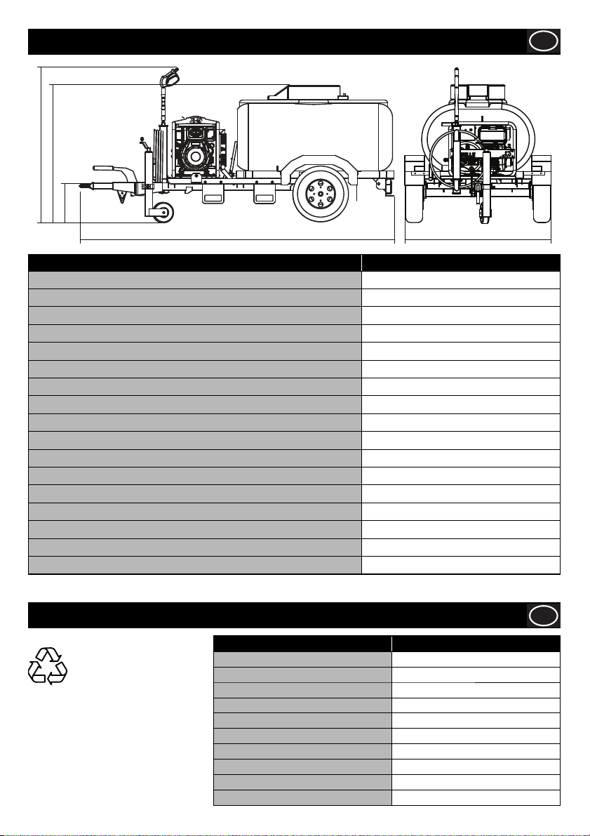
Technical Data
1480mm
1680mm
420mm
3454mm 1550mm
Model BWX 15/250D
Unladen Weight / Max Laden Weight (Kg) 460 / 1500
Towing Height (mm) 420
Water Tank Capacity (Ltrs) 1125
Tyre Size (mm) 175 x 13 -8
Tyre Pressure (psi - bar) 60 - 4.13
*Max. Towing Speed (mph) 60
Tow Eye Type 40mm Ring Eye
Engine Yanmar L100 Electric Start
Engine Power (Hp-kW) 8.9 - 6.6
Water Flow (lpm) 15
Max. Water Pressure (bar - psi) 250 - 3600
Max. Water Inlet Temperature (°) 40/45
Fuel Tank Capacity (Ltrs) 5.4
Gearbox Driven Pump Yes
Hose Length (M) 10
2
Vibration Level (m/sec
Sound Power Level (dB(A)) 110
*Always take into account the maximum speed limit per road as outlined in the highway code.
) <2.5
GB
Safe Disposal.
Instructions for the protection of
the environment. The machine
contains valuable materials.
Take the discarded apparatus
and accessories to the relevant
recycling facilities.
Environment
Component Material
Trailer Galvanised Steel & Rubber
Tank Polyethylene & Steel
Wheels Steel / Butyl Rubber
Mudguards HDPE
Pressure Washer Main Frame Steel
Lance Nylon, Stainless Steel & Brass
Engine Aluminium
Pump Steel, Aluminium & Brass
Flexible Mounts Steel and Rubber
Various Parts Steel and Aluminium
5
GB
Page 6
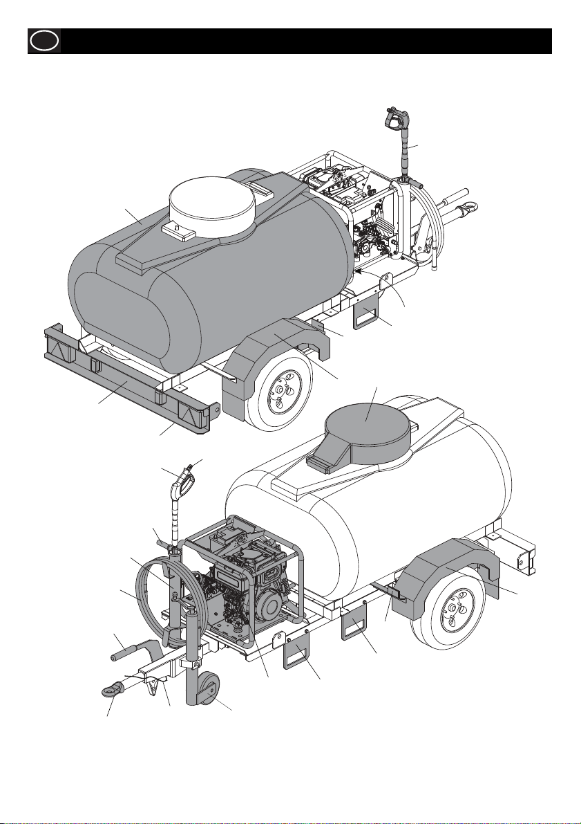
GB
1. Tank
2. Lance
3. Registration Plate
4. Lightboard
5. Mudguard
6. Refl ector
7. Pressure Washer
8. Tank Filler Cap
9. Lance Swivel Joint
10. Lance Trigger
Machine Description - Bowser
2
1
6
5
3
4
10
11
12
13
14
15
9
7
18
16
11. Detergent Control Handle
12. Lance & Hose Holder
13. High Pressure Hose
14. Handbrake
15. Ring Eye / Ball Hitch
16. Adjustable Jockey Wheel
17. Tank Drain Tap
18. Break Away Cable
19. Forktruck Tine Guides
17
8
5
6
6
Page 7
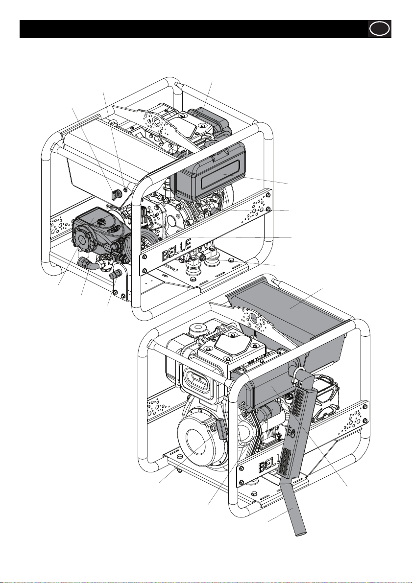
Machine Description - Pressure Washer
1. Key Start
2. Ignition / Low Oil Pressure Buzzer
& Warning Light
3. Air Cleaner
3
2
1
4. Pump
5. Pump Inlet
6. Pump Outlet
7. Fuel Tank
7
10
8
9
GB
4
5
8. Engine Speed Control
9. Detergent Inlet Strainer
10. Engine Oil Drain
11. Battery Housing
12. Exhaust
13. Exhaust Extension
14. Starter Motor
15. Recoil Start
11
6
15
14
1
13
12
7
Page 8
GB
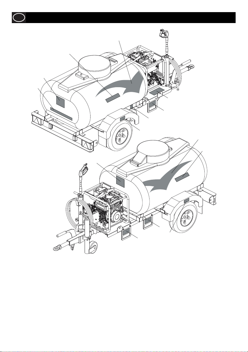
Decals - Bowser
A
B
A
A
D
F
E
C
A
B
A
F
C
F
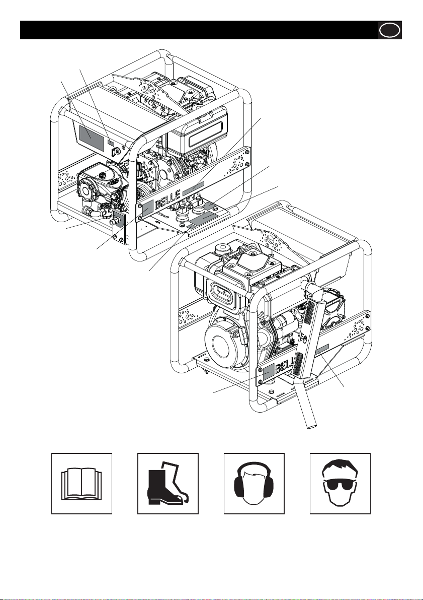
A. Altrad Branding Decals.
B. Model Identifi cation Decals - Identifi es the model of Bowser Pressure Washer
C. Tyre Pressure Decal
D. Drain Tap Decal - If the forecasted ambient temperature is below freezing, the Water Tank & Pump must be drained using the
Drain Tap. This decal indicates where the taps should be whilst operating the machine, draining the pump or draining the pump
and tank.
E. Statutory Plate - includes Type Approval Number, VIN (Vehicle Identifi cation Number) and Axle Weights
F. Forktruck Decal - highlights where the Bowser can be handled using a Forktruck.
NOTE:- DO NOT lift the Bowser when there is water in the tank.
G. Operating Decal - information on how to safely start the Bowser Pressure Washer.
H. Ignition Warning Light Decal - The Light is illuminated when the ignition is in the ON position but the mechanical engine stop
may be activated. A warning buzzer will also sound.
J. Altrad Logo Decal.
8
Page 9
Decals - Pressure Washer
GB
H
G
K
L
M
N
J
P
J
K. Model Identifi cation Decal - Identifi es the model of Pressure Washer.
L. Safety Information Decal - includes information on the model name, noise
level (in dB(A)) and safety symbols which are identifi ed below:-
Please Read
Operators Manual
M. Operating Safety Decal - highlights important safety information that must be read before operating the machine.
N. High Pressure Outlet Decal - highlights the position of the High Pressure Outlet on the machine.
P. Noise Decal - indicates the noise level of the machine.
Wear Protective
Footwear
Wear Ear
Protection
L
Wear Eye
Protection
9
Page 10

GB
For your own personal protection and for the safety of those around you, please read and ensure you fully understand the following
safety information. It is the responsibility of the operator to ensure that he/she fully understands how to operate this equipment safely.
If you are unsure about the safe and correct use of the Boswer, consult your supervisor or Altrad Belle.
IMPROPER SIZING OF THE TRAILER TO THE TOW VEHICLE
Trailers that weigh too much for the towing vehicle can cause stability problems, which can lead to death or serious injury.
Furthermore, the additional strain put on the engine and drive-train may lead to serious tow vehicle maintenance problems. For these
reasons the maximum towing capacity of your towing vehicle should not be exceeded (see Technical Data section)
DRIVING TOO FAST
With ideal road conditions, the maximum recommended speed for safely towing a trailer is 60mph. If you drive too fast, the trailer is
more likely to sway, thus increasing the possibility for loss of control. Also your tyres may overheat, thus increasing the possibility of a
blowout.
CAUTION
FAILURE TO ADJUST DRIVING BEHAVIOR WHEN TOWING A TRAILER
When towing a trailer, you will have decreased acceleration, increased stopping distance, and increased turning radius (which means
you must make wider turns to keep from hitting curbs, vehicles, and anything else that is on the inside corner). Furthermore, the
trailer will change the handling characteristics of your towing vehicle, making it more sensitive to steering inputs and more likely to be
pushed around in windy conditions or when being passed by large vehicles. In addition, you will need a longer distance to pass, due
to slower acceleration and increased length. With this in mind:
• Be alert for slippery conditions. You are more likely to be affected by slippery road surfaces when driving a tow vehicle with a
trailer, than driving a tow vehicle without a trailer.
• Anticipate the trailer “swaying.” Swaying can be caused by excessive steering, wind gusts, roadway edges, or by the trailer
reaction to the pressure wave created by passing trucks and busses.
• When encountering trailer sway, take your foot off the accelerator, and steer as little as possible in order to stay on the road. Use
small “trimlike” steering adjustments. Do not attempt to steer out of the sway; you’ll only make it worse. Also, do not apply the tow
vehicle brakes to correct trailer swaying. The application of the trailer brakes alone will tend to straighten out the combination,
especially when going downhill.
• Check rearview mirrors frequently to observe the trailer and traffi c.
• Use lower gear when driving down steep or long grades. Use the engine and transmission as a brake. Do not ride the brakes, as
they can overheat and become ineffective.
• Be aware of your trailer height, especially when approaching bridges, roofed areas and around trees.
IMPROPER LOADING
The total weight of the load you put in or on the trailer, plus the empty weight of the trailer itself, must not exceed the trailer’s Gross
Vehicle Weight rating (GVW). An overloaded trailer can result in loss of control of the trailer, leading to death or serious injury.
Never load a trailer so that the weight on any tyre exceeds its rating.
TRAILER NOT PROPERLY COUPLED TO THE HITCH
It is critical that the trailer be securely coupled to the hitch, and that the emergency breakaway brake lanyard is correctly attached.
Uncoupling may result in death or serious injury to you and to others.
• Make sure the hitch and ball are rated for the trailer.
• Make sure the hitch [ball size] matches the coupler.
• Check the hitch ball for wear, corrosion and cracks before coupling. Replace worn, corroded or cracked hitch ball before coupling
to the trailer.
• Make sure the hitch ball is tight to the hitch before coupling the trailer.
An improperly coupled trailer can result in death or serious injury. Do not move the trailer until:-
• The coupler is secured and locked;
• The safety chains are secured to the tow vehicle; and
• The trailer jacks are fully retracted.
Do not tow the trailer on the road until:-
• The trailer brakes are checked;
• The breakaway switch is connected to the tow vehicle;
• The load is secured to the trailer; and
• The trailer lights are connected and checked.
CORRECT CONNECTION OF BREAKAWAY BRAKE
Your trailer is equipped with brakes and a breakaway brake system that can apply the brakes on your trailer, if your trailer comes
loose from the hitch for any reason.
An ineffective breakaway brake system can result in a runaway trailer, leading to death or serious injury if the coupler or ball hitch
fails. Test the function of the breakaway brake system before towing the trailer. Do not tow the trailer if the breakaway brake
system is not working; have it serviced or repaired.
Connect the breakaway lanyard to the tow vehicle NOT to the hitch, ball or support.
Driving too fast for conditions can result in loss of control and cause death or serious injury.
Adjust speed down when towing trailer.
General Safety - Bowser
10
Page 11
General Safety - Bowser
MATCHING TRAILER AND HITCH
WARNING
WORN TYRES, LOOSE WHEELS AND Wheel NUTS
Just as with your tow vehicle, the trailer tyres and wheels are important safety items. Therefore, it is essential to inspect the trailer
tyres before each tow.
If a tyre has a bald spot, bulge, cut, cracks, or is showing any cords, replace the tyre before towing. If a tyre has uneven tread wear,
take the trailer to a dealer service center for diagnosis. Uneven tread wear can be caused by tyre imbalance, axle misalignment or
incorrect infl ation.
Tyres with too little tread will not provide adequate frictional forces on wet roadways and can result in loss of control, leading to death
or serious injury.
Improper tyre pressure causes increased tyre wear and may reduce trailer stability, which can result in a tyre blowout or possible loss
of control. Therefore, before each tow you must also check the tyre pressure. Remember, the correct tyre pressure is listed on the
Certifi cation (VIN) label, and should be checked when tyres are cold. Allow 3 hours cool-down after driving as much as 1 mile at
40 mph before checking tyre pressure
The tightness of the wheel nuts is very important in keeping the wheels properly seated to the hub. Before each tow, check to make
sure they are tightened to the correct torque.
CAUTION
The correct tightening sequence and tightness (torque) for wheel nuts is listed in the “Inspection, Service & Maintenance” chapter of
this manual. Use a calibrated torque wrench to tighten the wheel nuts.
Wheel nuts are also prone to loosen after fi rst being assembled. When driving a new trailer (or after wheels have been remounted),
check to make sure they are tightened to the correct torque after the fi rst 10, 25 and 50 miles of driving and before each tow
thereafter.
Failure to perform this check can result in a wheel parting from the trailer and a crash, leading to death or serious injury.
CAUTION
TYRE SAFETY TIPS
Preventing Tyre Damage
• Slow down if you have to go over a pothole or other object in the road.
• Do not run over curbs or other foreign objects in the roadway, and try not to strike the curb when parking.
Tyre Safety Checklist
• Check tyre pressure regularly (at least once a month), including the spare.
• Inspect tyres for uneven wear patterns on the tread, cracks, foreign objects, or other signs of wear or trauma.
• Remove bits of glass and foreign objects wedged in the tread.
• Make sure your tyre valves have valve caps.
• Check tyre pressure before going on a long trip.
• Do not overload your vehicle. Check the tyre information placard or owner’s manual for the maximum recommended load for the
vehicle.
WEIGHT AND LOAD DISTRIBUTION
Correct loading of your trailer is essential for your safety. Tire, wheel, axle or structural failure can be caused by overloading.
CAUTION
INAPPROPRIATE CARGO
Your trailer is designed for specifi c cargo, only carry that cargo in the trailer. Your trailer must not be used to carry certain items, such
as people, containers of hazardous substances or containers of fl ammable substances.
TRANSPORT USING A FORKTRUCK
• DO NOT lift the Bowser when there is water in the tank.
• Only use the designated Forktruck Tine Guides, highlighted by the decals.
Use of an under-rated hitch, ball or tow vehicle can result in loss of control leading to death or serious
injury. Make certain your hitch and tow vehicle are rated for your trailer.
Metal creep between the wheel rim and wheel nuts (bolts) will cause rim to loosen.
Death or injury can occur if wheel comes off. Tighten wheel nuts (bolts) before each tow.
Inadequate wheel nut torque can cause a wheel to part while towing. Death or serious injury can
result. Make sure wheel nuts are tight before towing trailer.
An overloaded trailer can result loss of control of the trailer, leading to death or serious injury. Never
load a trailer so that the weight on any tire exceeds its rating. Never exceed the trailer Gross Vehicle
Weight rating (GVW).
GB
11
Page 12
GB
INOPERABLE BRAKES, LIGHTS OR MIRRORS
Be sure that the brakes and all of the lights on your trailer are functioning properly before towing your trailer. Lights on a trailer are
controlled via a connection to the tow vehicle, generally a multi-pin electrical connector.
Check the trailer taillights by turning on your tow vehicle headlights. Check the trailer brake lights by having someone step on the tow
vehicle brake pedal while you look at trailer lights. Check the turn signal lights by operating the turn signal lever in the tow vehicle.
CAUTION
If your trailer has hydraulic “surge” brakes, pull the emergency breakaway brake lanyard to check the operation of the surge
mechanism.
Standard mirrors usually do not provide adequate visibility for viewing traffi c to the sides and rear a towed trailer. You must provide
mirrors that allow you to safely observe approaching traffi c.
HAZARDS FROM MODIFYING YOUR TRAILER
Essential safety items and structural integrity can be damaged by altering your trailer.
Alteration of the trailer structure or modifi cation of mechanical, electrical, hydraulic or other systems on your trailer must be performed
only by qualifi ed technicians who are familiar with the system as installed on your trailer.
Failure to connect the tow vehicle lighting and braking to the trailer will result in
inoperable lights and brakes, and can lead to collision.
General Safety - Bowser
GB
A ball hitch / ring coupler connects to a ball that is located on or under the rear
bumper of the tow vehicle. This system of coupling a trailer to a tow vehicle is
sometimes referred to as “bumper pull.”
A ball hitch / ring coupler trailer may be fi tted with a tongue jack that can raise
and lower the coupler. The tongue jack is mounted to the A-frame (front, or
tongue) part of the trailer. By rotating the jack handle clockwise, the jack will
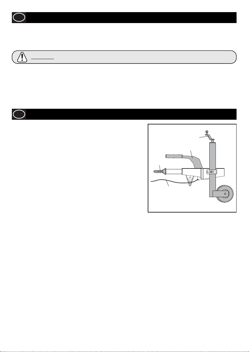
extend and raise the tongue of the trailer. Figure 1 shows a trailer with a ball
hitch coupler.
Be sure the ball hitch / ring coupler coupler is suitable for the size and weight of
the trailer. The load rating of the coupler and the necessary ball size are listed
on the trailer tongue. You must provide a hitch and ball for your tow vehicle,
where the load rating of the hitch and ball is equal to or greater than that of
your trailer. Also, the ball size must be the same as the coupler size. If the hitch
ball is too small, too large, is underrated, is loose or is worn, the trailer can
come loose from the tow vehicle, and may cause death or serious injury.
THE TOW VEHICLE, HITCH AND BALL MUST HAVE A RATED TOWING
CAPACITY EQUAL TO OR GREATER THAN THE TRAILER GROSS VEHICLE
WEIGHT RATING (GVW).
IT IS ESSENTIAL THAT THE HITCH BALL BE OF THE SAME SIZE AS THE COUPLER.
IF THE HITCH BALL IS TOO SMALL, IS UNDERRATED, IS LOOSE OR IS WORN, THE TRAILER CAN COME LOOSE FROM THE
TOW VEHICLE, RESULTING IN DEATH OR SERIOUS INJURY.
The ball size and load rating (capacity) are marked on the ball; hitch capacity is marked on the hitch.
BEFORE COUPLING THE TRAILER TO THE TOW VEHICLE
• Be sure the size and rating of hitch ball match the size and rating of the coupler. Hitch balls and couplers are marked with their
size and rating.
• Wipe the hitch ball clean and inspect it visually and by feel for fl at spots, cracks and pits.
• Rock the ball to make sure it is tight to the hitch, and visually check that the hitch ball nut is solid against the lock washer and
hitch frame.
• Wipe the inside and outside of the coupler clean and inspect it visually for cracks and deformations; feel the inside of the coupler
for worn spots and pits.
• Be sure the coupler is tight to the tongue of the trailer. All coupler fasteners must be visibly solid against the trailer frame.
ATTACH AND TEST THE BREAKAWAY BRAKE SYSTEM
If the coupler or hitch fails, a properly connected and working breakaway brake system will apply brakes on the trailer.
Visually inspect the breakaway system for broken or missing parts. Repair or replace worn, damaged or missing parts before towing
trailer.
An ineffective breakaway brake system can result in a runaway trailer, leading to death or serious injury if the coupler or ball hitch
fails.
Test the function of the breakaway brake system before towing the trailer. DO NOT tow the trailer if the breakaway brake system is
not working; have it serviced or repaired. Connect the breakaway lanyard to the tow vehicle - NOT to the hitch, ball or support.
Coupling To The Tow Vehicle
Tow Ring/Ball Hitch
Breakaway Cable
Figure. 1
Adjustable
Jockey Wheel
Handbrake
12
Page 13
Breaking In A New Trailer
RETIGHTEN WHEEL NUTS AT FIRST 10, 25 & 50 MILES
Wheel wheels can shift and settle quickly after being fi rst assembled, and must be checked after the fi rst 10, 25 and 50 miles of
driving. Failure to perform this check may result in a wheel coming loose from the trailer, causing a crash leading to death or serious
injury. Refer to the “Service & Maintenance” section for the correct tightening sequence and torque value for the wheel wheels nuts
(bolts).
CAUTION
TYRE PRESSURE
Check tire pressures on both the trailer and tow vehicle. Infl ate to the value indicated on the trailer Certifi cation/VIN label located on
the right front side.
Wheel nuts are prone to loosen after being fi rst assembled. Death or serious injury can result.
Check wheel nuts for tightness on a new trailer, and after re-mounting a wheel at 10, 25 and 50 miles.
GB
13
Page 14
GB
For your own personal protection and for the safety of those around you, please read and ensure you fully understand the following
safety information. It is the responsibility of the operator to ensure that he/she fully understands how to operate this equipment safely.
If you are unsure about the safe and correct use of the Pressure Washer, consult your supervisor or Altrad Belle.
BEFORE STARTING THE PRESSURE WASHER
CAUTION
• This equipment is heavy and must not be lifted single-handedly. Where possible, please use the integrated wheels to transport
the Pressure Washer otherwise GET HELP or use suitable lifting equipment on the lifting point.
• Always switch OFF the engine before transporting, moving it around the site or servicing it.
• Cordon off the work area and keep members of the public and unauthorised personnel at a safe distance.
• Suitable PPE must be worn when using this equipment and should meet relevant EEC/local standards: waterproof clothing / boots
/ gloves, safety goggles, helmet or helmet & visor and ear defenders. Tie back long hair and remove any jewellery which may
catch in the equipment’s moving parts.
• Become familiar with the controls before operating the Pressure Washer and make sure you know how to safely switch this
machine OFF before you switch it ON in case you get into diffi culty.
• Never remove or tamper with any guards fi tted, they are there for your protection. Always check guards for condition and
security, if any are damaged or missing, DO NOT USE THE PRESSURE WASHER until the guard has been replaced or repaired.
• DO NOT operate the Pressure Washer when you are ill, feeling tyred, or when under the infl uence of alcohol or drugs.
• ALWAYS ensure the water pressure is released before starting the engine. This can be done safely by depressing the trigger.
• ALWAYS ensure high-pressure hose is connected before starting the engine.
• Replace any worn/damaged decals.
• Remove all packaging material before operating.
WHEN OPERATING THE PRESSURE WASHER
• During use the engine becomes very hot, allow the engine to cool before touching it. Never leave the engine running and
unattended.
• EXHAUST FUMES CAN KILL - Ensure plenty of ventilation when running petrol/diesel engines in a confi ned area.
• Place the Pressure Washer at least 3 metres away from buildings and other equipment during operation.
• High pressure jets can be dangerous if misused. The lance must not be aimed at persons, animals, live electrical equipment or the
machine itself.
• DO NOT run the pump dry for more than 30 secs. This will cause internal damage.
• DO NOT leave engine running whilst not in use for long periods. This may cause damage to internal components.
• DO NOT use the Presssure Washer on any equipment that is connected to mains electrical supply. ENSURE all electrical
components are covered and check for water ingress before reconnecting to the mains supply.
• NEVER disconnect a hose with pressure in it or allow a hose to be fl attened / kinked.
• ALWAYS drain water from pump after operating in cold conditions to prevent frost damage.
• DO NOT use the Pressure Washer whilst positioned on a ladded. Use a suitable platform or scaffolding.
FUEL SAFETY
• Before refuelling, switch off the engine and allow it to cool.
• When refuelling, DO NOT smoke or allow naked fl ames in the area.
• Refuel in a well ventilated area with the engine switched off. Check for spilled fuel or leaks.
• Spilt fuel must be made safe immediately, using sand. If fuel is spilt on your clothes, change them.
• Store fuel in an approved, purpose made container away from heat and ignition sources.
General Safety - Pressure Washer
Improper maintenance or use can be hazardous. Read and Understand this section before you
perform any maintenance, service or repairs.
CAUTION
SAFETY AND ACCIDENT PROTECTION
Operating Instructions:
All persons who apply, assemble, operate, start, control, maintain or repair this machine must read and understand these operating
instructions.
Owner Responsibility:
The owner must ensure that only qualifi ed persons operate, maintain, or repair this machine.
Storage:
When not in use, store in a dry, locked place. Keep away from children.
Transport :
This equipment is heavy and must not be lifted single-handedly. Where possible, please use the integrated wheels to transport
the Pressure Washer otherwise GET HELP or use suitable lifting equipment on the lifting point.
NOTE:- ALWAYS ensure handle is always locked in placed when transporting the machine
Fuel is fl ammable. It may cause injury and property damage. Shut down the engine, extinguish all
open fl ames and do not smoke while fi lling the fuel tank. Always wipe up any spilled fuel.
14
Page 15
Start and Stop Procedure
STOPPING - Yanmar L100
• In preparation for stopping the engine, move the throttle lever to LOW position.
• Allow the engine to idle.
• Move the Throttle Lever to STOP position to stop the engine. Then, set the Key Switch to “OFF” position.
STARTING - Yanmar L100 Electric Start
• Insert the key into the key switch.
• Place the throttle into the mid-way postion.
• Turn the key clockwise to the START position. Release the key as soon as the engine starts, it will return to the ON position.
STARTING - Yanmar L100 Manual Start
• Grasp the recoil starter handle.
• Pull the handle out slowly until you feel strong resistance.
• Slowly return the recoil starter to the initial position.
• Push the decompression lever down and then release it. The decompression lever will automatically return to the original position
when the engine starts.
• Grasp the recoil starter handle.
• Pull the handle all the way out with a strong and even motion. Use two hands if necessary.
• Slowly return the starter handle to the initial position.
• If the engine does not start, repeat the procedure.
GB
CAUTION
The max. engine running speed is pre-set by the manufacturer and must not be adjusted.
15
Page 16
GB
Operating Instructions - Pressure Washer
WARNING
PRE-OPERATION
• Check your Pressure Washer before use and IMMEDIATELY replace any damaged parts.
• Place the Pressure Washer on fi rm level ground with the engine switched OFF.
• Check the engine oil level, low oil levels will result in the engine not starting.
• Check the fuel level.
• This equipment is could emit a Sound Power Level (LWA) of up to 110dB(A). See Technical Data section for more details and wear
appropriate ear defenders.
• Your Altrad Belle Pressure Washer comes preset and NO adjustment is necessary.
• Be aware of how to stop the Pressure Washer by use of the On/Off switch or throttle lever.
Refer to the engine and pump manuals provided for full pre-operation check.
HOSE CONNECTION - HIGH PRESSURE OUTLET (MACHINE MUST BE TURNED OFF)
• Ensure in-line fi lters are in good condition and not removed.
• Check condition of the o-rings in the ends of the hose.
• Attach the high pressure hose to the pump connection.
• Attach the lance to opposite ends of the high pressure hose.
CAUTION
OPERATION
• Turn on the water supply.
• Start the engine (see start and stop procedure)
• Aim the lance at the area being cleaned and press the lance trigger.
• Adjust the pressure regulator to obtain required working pressure. ALWAYS use on full throttle.
CAUTION
• On completion of the job, stop the engine (see start and stop procedure)
• Turn off the water supply.
• Press the lance trigger to release the pressure within the lance.
Before you operate or carry out any maintenance on this machine YOU MUST READ and STUDY
this manual.
When connection to temporary / gravity-fed supply, always ensure supply hose is primed with water to
ensure pump is not run dry on start-up. Running dry will permanently damage the pump.
The high pressure of water may cause the lance to jolt. Ensure you have a good grip of the lance
before operating the pressure washer.
CAUTION
When Using Detergents
• Set the machine up as for using water.
• Connect the detergent hose to the machine and place the fi lter end into the detergent supply.
• Loosen detergent control valve.
• Loosen control handle to deliver detergent.
• On completion of the job, fl ush out the hose and lance with clean water to remove any residual detergent.
• Tighten detergent control valve.
• Tighten control handle.
When Using the Hose Reel
NOTE: When using the pressure washer with a hose reel, the high pressure outlet on the front of the machine becomes redundant.
You can use this coupling to attach the hose for storage purposes.
• Pull the securing pin in the side of the hose reel to release the reel. Unravel the hose to the desired length.
• Connect the hose to the lance.
• On completion of the job, remove the hose from the lance and reel the hose back in.
• Connect your hose to the coupling if you desire.
Always drain water from pump after operating in cold conditions to prevent frost damage.
16
Page 17
Troubleshooting Guide - Bowser
GB
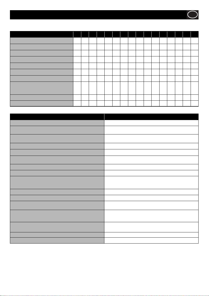
= MOST LIKELY CAUSE = LIKELY CAUSE
Symptom A B C D E F G H I J K L M N O P
Brakes over-heating
Trailer failing to auto-reverse
Hand brake not working effi ciently
Brakes not working effi ciently
Brakes snatching
Trailer ‘snaking’
Trailer swerving to one side
Brakes remaining on after hand
brake has been released
Trailer failing to tow easily (resistance)
Trailer brakes are jerky
Problem Remedy
A - Brake Shoes - too tight, wheels not rotating correctly. Reset Brakes according to the reset procedure.
B - Brake Cable - sticking, dirty, trapped or corroded.
C - Brake Spring broken or dislodged.
D - Brake Shoes - Worn Remove hubs, clean brakes and drums, replace brake shoes.
E - Hitch incorrectly adjusted. Follow adjustment procedure as laid down.
F - Cable linkage system incorrectly adjusted, sticking.
G - Cable system insuffi ently supported or supports broken. Re-fi t fl exible supports under trailer to reduce friction in system.
H - Trailer moves backwards on slippery surface. Use manual stop on over-run coupling (if fi tted)
I - Hand brake left ‘on’ or ‘partially on’.
J - Damper failing in coupling. Contact Altrad Belle.
K - Coupling shaft jammed or damaged / rusty. Contact Altrad Belle.
L - Incorrect nose weight on trailer coupling.
M - Rust formation on hub grease in brake drum.
N - Brake Shoe carrier rollers are rusty, damaged / worn.
O - Brakes not equally adjusted on all wheels. Jack-up the trailer and adjust.
P - Wrong tyre pressures. Check tyre pressures and infl ate to the correct recommendations.
Remove Cables, clean and re-grease and fi t to the reset
procedure.
Remove hubs, clean brakes and drums, refi t new springs and
brake shoes.
Remove linkages, cables and rods then clean, refi t and re-adjest
linkage system.
Ensure hand brake fully off - if vehicle has been driven
extensively with hand brake on, remove hubs, check brakes and
hub bearing - replace if necessary.
Adjust load to give between 50 - 100kgs ‘Nose weight’ on trailer
coupling.
Remove hubs/drums, clean carrier shoe with a wire brush.
Grease rollers with ‘Copperslip’ or similar material, refi t and
adjust.
Remove hubs and brakes, clean carrier shoe with wire brush.
Grease rollers with ‘copperslip’ or similar material, refi t and adjust.
17
Page 18
GB
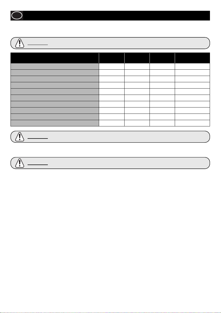
You must inspect, maintain and service your trailer regularly to insure safe and reliable operation. If you cannot or are unsure how
to perform the items listed here, have your dealer do them. Note: In addition to this manual, also check the relevant component
manufacturer’s manual.
CAUTION
Service and Maintenance - Bowser
Regular maintenance with particular attention to the Brake condition / adjustment and Bearings is vital
to the safety of the trailer.
Attention Weekly
Check and adjust Brakes
Check and adjust system
Grease Linkages and Cables
Grease and Check Over-Run Coupling
Check Tyre Pressures
Check and Grease Hubs
Check Wheel Nut Tightness
Check Tyre Tread Depth
Check Hub Adjustment
Remove Hubs - Check Brakes, Bearings
CAUTION
LIGHTS AND SIGNALS
Before each tow, check the trailer taillights, stoplights, turn signals and any clearance lights for correct operation.
CAUTION
WHEEL RIMS
If the trailer has been struck, or impacted, on or near the wheels, or if the trailer has struck a curb, inspect the rims for damage (i.e.
being out of round); and replace any damaged wheel. Inspect the wheels for damage every year, even if no obvious impact has
occurred.
Never install aftermarket wheels or wheel nuts on your trailer. Use only original equipment wheels and wheels nuts. Aftermarket
wheels and wheel nuts may not meet the load carrying requirements, pressure capacity and offset as the original equipment.
WHEEL NUTS (BOLTS)
• Be certain you have a clear understanding of the specifi c wheel maintenance responsibilities your vehicle manufacturer requires
/recommends you, as the owner, must perform in order to insure your wheel equipment is safely maintained. Check the wheel nut
tightness the fi rst 10, 25 and 50 miles of driving and before each tow thereafter. Refer to the owner’s manual and speak with your
dealer if you have any questions about correct tightening practices.
• The only way to be certain you have checked the tightness or torqued the wheel nuts to the correct value is with a torque wrench.
Fourway wrenches, ratchets, and similar tools can be useful for short-term emergency repairs but are not appropriate tools for
accurately checking wheel nut torque. You must use a torque wrench to accurately indicate the torque that you are applying to the
wheel nut.
• Keep a record of the date and approximate mileage when you check the wheel nut torque. Note any wheel nut that has lost
torque.
Investigate the reason(s) if the wheel nut torque is not maintained after more than one re-torque application, because this
indicates there is something wrong with the wheel nuts, nut studs, wheels and/or hubs and should be corrected.
• Contact your dealer or vehicle manufacturer immediately if you experience any persistent wheel nut loosening or any other wheel,
wheel or axle problems.
• In the event of a wheel separation incident, notify the vehicle manufacturer and dealer. Seek prompt professional assistance in
assessing the trailer and its gear, and retain, but don’t re-use involved wheels, wheels and studs.
DO NOT repair or service the trailer yourself. Contact a trained technician.
Worn or broken suspension parts can cause loss of control and injury may result.
Have trailer professionally inspected annually and after any impact.
To avoid collisions, taillights, stoplights and turn signals must work.
First 1200
Miles
Every 2500
Miles
Every 16000 Miles /
Annually
18
Page 19
Service and Maintenance - Bowser
WHEEL NUTS (BOLTS) Cont.
Tighten the wheel nuts to the correct tightness to prevent wheels from coming loose.
Refer to the steps that follow and the axle manufacturer’s information. Use a calibrated
torque wrench to tighten the wheel nuts. Over-tightening may result in breaking the
studs or permanently deforming the mounting stud holes in the wheels.
Remove all excess paint, oil and grease from mounting surfaces.
Start all wheel nuts by hand to prevent cross threading.
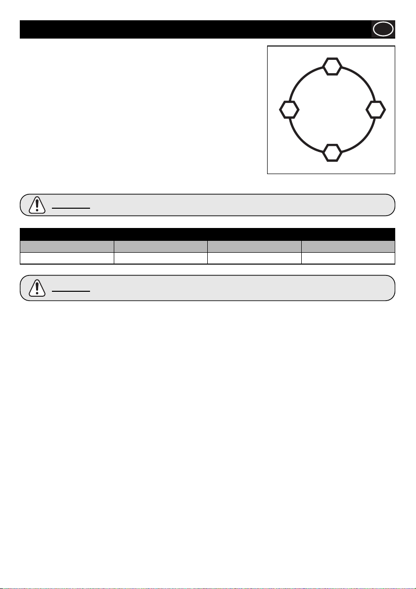
Tighten wheel nuts in sequence shown in in Figure 2.
NEVER install aftermarket wheels or wheel nuts on your trailer. Use only original
equipment wheels and wheels nuts. Aftermarket wheels and wheel nuts may not meet
the load carrying requirements, pressure capacity and offset as the original equipment.
NEVER install aluminum wheels on hubs/studs that were designed for steel wheels.
The stud length required for aluminum wheels is greater than that required for steel
wheels.
GB
1
43
2
Figure. 2
CAUTION
Stud Size 1st Stage 2nd Stage 3rd Stage
M12 30Nm 60Nm 100Nm
CAUTION
Information or torque values stamped on nuts supersedes the information listed in this manual.
WHEEL NUT TORQUE
Wheel nuts are prone to loosen right after a wheel is mounted to a hub. When driving on a remounted
wheel, check to see if the wheel nuts are tight after the fi rst 10, 25 and 50 miles of driving and before
each tow thereafter.
19
Page 20
GB
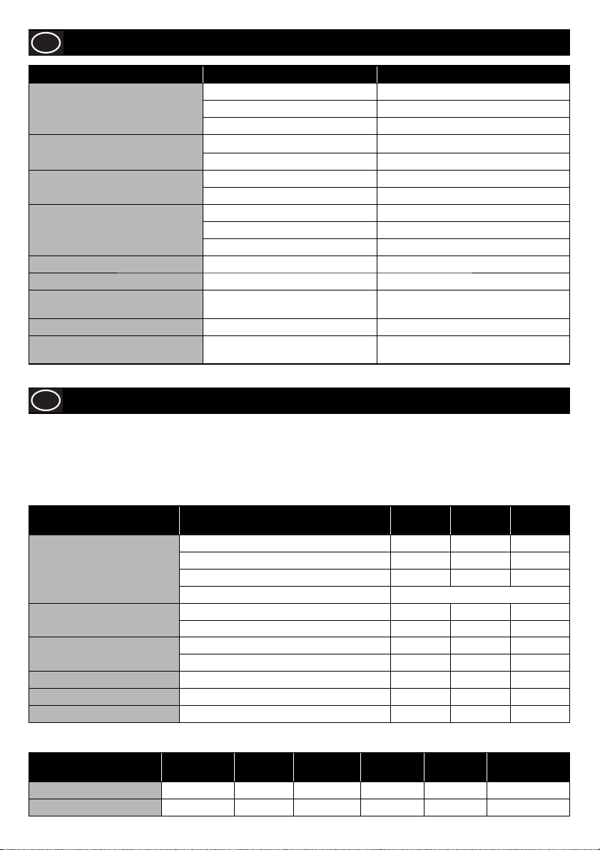
Problem Cause Remedy
Machine stops suddenly or will not
start.
Sudden pressure loss.
Low pressure.
Low pressure, machine is noisy and
vibrates.
Pump will not by-pass. Non-return valve dirty or jammed. Clean or replace.
Water drips from pump box. Pump seals worn. Replace.
Oil drips from pump bottom. Oil seal worn. Replace.
Oil is cloudy. Water ingress through oil fi lter pwheel. Rinse pump out and replace oil
Water leaks occasionally from
underneath the machine.
Troubleshooting Guide - Pressure Washer
Low oil. Check and top-up oil.
Flat battery. Check / replace battery.
Blown fuse. Check / replace fuse.
No water supply. Check supply & fi lters.
No chemical supply. Check chemical reservoir, close valve.
High pressure nozzle worn Replace high pressure nozzle.
Unloader set incorrectly. Set unloader to correct setting.
Valves worn or blocked. Clean / replace as required.
Piston seals worn. Replace.
Pump sucking air. Check water supply pipe and unions.
Pump seals worn.
Water in pump too hot. Release pressure by
operating the lance.
GB
The following schedule details the attentions considered necessary to ensure satisfactory operation of the Pressure Washer.
NOTE:- The attentions and periods summarised in the schedule are the initial recommendations and should be revised to suit the
Power Unit working conditions. Only authorised dealers should repair the Pressure Washer, and within the requirements of
the CE mark (where applicable), where no deviation from the original specifi cation must take place.
Please refer to the Engine Manufacturers instruction leafl et, before attempting any maintenance checks or procedures.
Item Attention Daily
Engine
Hoses
Pump
Fuel Filter Replace.
Water Filter Clean.
High Pressure Nozzle Replace.
Oil / Fuel Type & Quantity - Spark Plug Type
Diesel Yanmar L100 SAE 15W 40 1.65 Diesel 5.4 N/A N/A
Gearbox
Service and Maintenance - Pressure Washer
Check oil level and top up a required
Check fuel level and top up a required
Drain fuel tank and refi ll.
Oil change See relevant engine manual
Check connections for leaks or damage.
Check condition for damage.
Check oil, drain and replace.
Replace seals.
Oil Type
SAE 15W 40 0.65 N/A N/A N/A N/A
Quantity
(Litre)
Fuel Type
Capacity
(Litre)
Spark Plug
Type
6 Months /
500 Hours
Yearly /
1000 Hours
Electrode
Gap (mm)
20
Page 21
Replacement Parts
Contact your nearest Altrad Belle dealer. When ordering replacement parts, please quote the product type, serial number &
engine/motor model. Detail the part required in conjunction with the parts list provided, indicating the Page Number, Item Number and
quantity required.
GB
Warranty
Your new Altrad Belle Pressure Washer is warranted to the original purchaser for a period of one-year (12 months) from the original
date of purchase. The Altrad Belle warranty is against defects in design, materials and workmanship.
The following are not covered under the Altrad Belle warranty:
1. Damage caused by abuse, misuse, dropping or other similar damage caused by or as a result of failure to follow assembly,
operation or user maintenance instructions.
2. Alterations, additions or repairs carried out by persons other than Altrad Belle or their recognised agents.
3. Transportation or shipment costs to and from Altrad Belle or their recognised agents, for repair or assessment against a
warranty claim, on any machine.
4. Materials and/or labour costs to renew, repair or replace components due to fair wear and tear.
The following components are not covered by warranty.
• Engine air fi lter
• Engine spark plug / injector
• Nozzles
Altrad Belle and/or their recognised agents, directors, employees or insurers will not be held liable for consequential or other
damages, losses or expenses in connection with or by reason of or the inability to use the machine for any purpose.
Warranty Claims
All warranty claims should fi rstly be directed to Altrad Belle, either by telephone, by Fax, by Email, or in writing.
For warranty claims:
Write to:
Altrad Belle Warranty Department,
Sheen, Nr. Buxton,
Derbyshire,
SK17 0EU
England.
Warranty Registration:
In the bid for ALTRAD Belle to become greener and more eco friendly, we have now introduced online
Warranty registration. To access the registration page of our website, please use the following address:-
http://www.bellegroup.com/index.php?p=warranty_registration
Alternatively, please scan the adjacent QR Code (Quick Response Code) using your smartphone to access
the registration page.
GB
21
Page 22
1-01
1
2
3
12
4
11
6
4
7
5
6
8
9
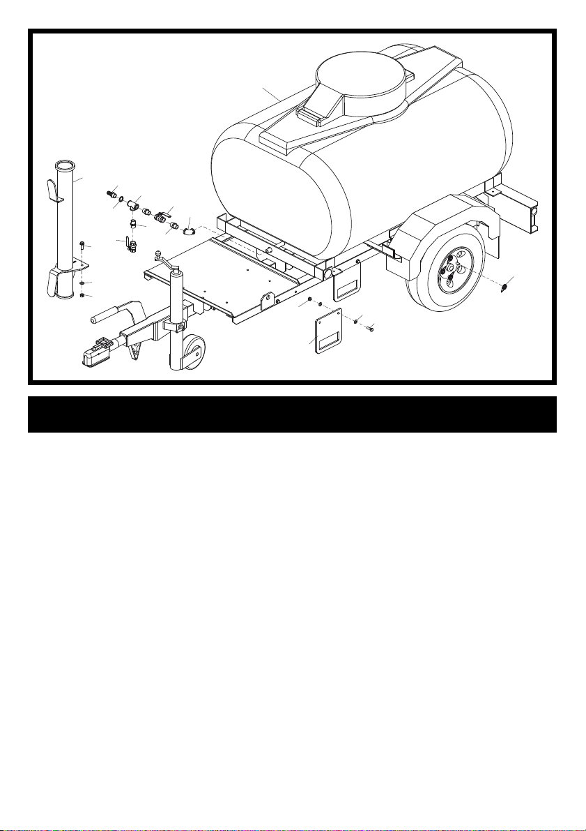
Trailer Assembly 1
1 995/02500 ........... Bowser Trailer ........................ Orange ....................1
1 995/02600 ........... Bowser Trailer ........................ Red .......................... 1
2 995/03500 ........... Lance Holster .......................................................... 1
3 6/0318 ................. Hosetail ..................................19mm ...................... 1
4 6/0321 ................. Ball Valve ................................................................ 2
5 6/0317 ................. Elbow ...................................................................... 1
6 6/0319 ................. Adaptor ................................................................... 3
7 7/10003 ...............Screw .....................................M10 x 35 .................. 2
8 4/1005 ................. Washer ..................................M10 ......................... 2
9 8/10006 ............... Nut .........................................M10 .........................2
10 1/1120 ................. Wheel Nut Marker ................................................... 4
11 5/0086 ................. Seal ........................................M16 ......................... 1
12 6/0325 ................. Tee Adaptor ............................................................1
13 995/99943 ........... Bracket .................................................................... 4
14 7/12030 ............... Screw ...................................................................... 8
15 4/1204 ................. Washer ................................................................... 16
16 8/10023 ............... Nut ..........................................................................8
10
16
15
14
13
22
Page 23
1-02
20
46
49
47 48
50
21
1
2
3
7
4
6
5
8
9
10
12
11
14
13
16
15
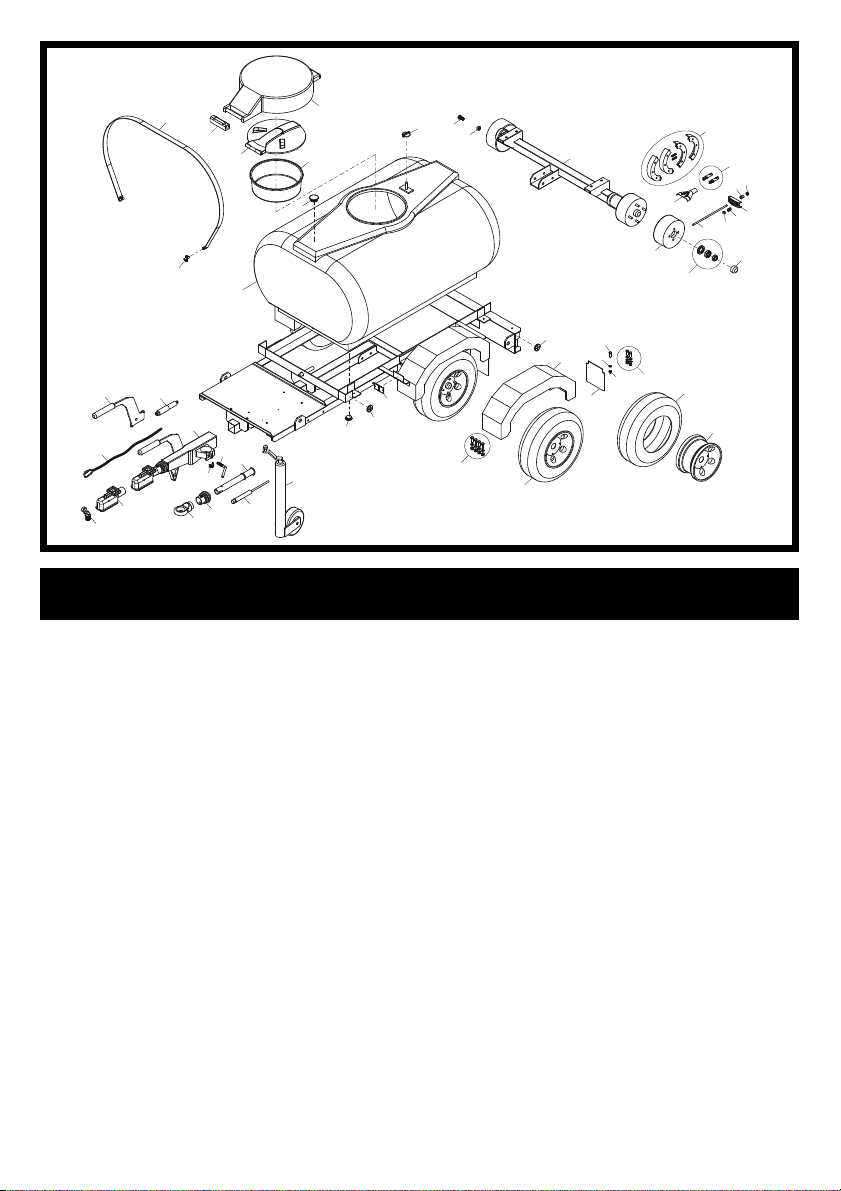
Trailer Assembly 2
1 995/99948 ........... Tank ........................................................................1
2 995/99985 ........... Handbrake Lever ....................................................1
3 995/99986 ........... Energy Store ........................................................... 1
4 ............................ Brake Away Cable .................................................. 1
5 995/99973 ...........Lock Kit (for 50mm Ball Hitch) ................................ 1
6 995/99945 ...........50mm Ball Hitch ......................................................1
7 995/99952 ...........50mm Ball Hitch Coupling Complete ...................... 1
8 995/99998 ........... Locking Handle ....................................................... 1
9 995/99953 ........... Drawtube ................................................................ 1
10 995/99999 ........... Locking Pad ............................................................1
11 995/99946 ........... 40mm Ring Hitch .................................................... 1
12 995/99955 ........... Gater ....................................................................... 1
13 995/99954 ........... Damper ................................................................... 1
14 995/99957 ........... Jockey Wheel Complete ......................................... 1
15 995/99984 ........... Plug ......................................................................... 1
16 73/0060 ............... Reflector - Amber .................................................... 4
17 73/0059 ............... Reflector - Clear ...................................................... 2
18 995/99899 ........... Mudguard Fastener Kit ...........................................2
19 995/99962 ........... Wheel ...................................................................... 2
20 995/99981 ........... Strap cw Retaing Bars ............................................ 2
21 995/99983 ........... Retaining Bar ..........................................................4
22 995/99988 ........... Wheel Rim .............................................................. 2
23 995/99987 ........... Tyre ......................................................................... 2
24 995/99898 ........... Mudflap Fastener Kit ............................................... 1
25 995/99979 ........... Mudflap ................................................................... 2
26 995/99996 ........... Nut ..........................................................................4
27 995/99997 ........... Washer ................................................................... 4
28 995/99995 ........... Screw ...................................................................... 4
29 995/99961 ........... Mudguard ................................................................ 2
30 995/99976 ........... Grease Cap_Small ................................................. 2
31 995/99972 ........... Bearing Kit .............................................................. 2
32 995/99970 ........... Hub .........................................................................2
33 995/99974 ........... Brake Rod ...............................................................2
34 995/99991 ........... Dome Nut ...............................M8 ........................... 2
35 995/99992 ........... Locking Nut ............................M8 ...........................2
36 995/99977 ........... Balance Bar ............................................................ 2
37 995/99994 ........... Locking Nut ............................M10 .........................2
38 995/99993 ........... Locking Nut ............................M10 .........................2
39 995/99978 ........... Eyelets .................................................................... 2
40 995/99975 ........... Shroud ....................................................................2
41 995/99971 ........... Brake Shoes ........................................................... 2
42 995/99969 ........... Axle Complete ........................................................ 1
43 995/99990 ........... Wheel Nut ............................................................... 8
45
44
43
42
40
32
16
28
27
29
24
26
17
25
18
19
44 995/99989 ........... Wheel Stud ............................................................. 8
45 3/1007 ................. Linch Pin ................................................................. 1
46 995/99949 ........... Outer Lid ................................................................. 1
47 995/99950 ........... Inner Lid .................................................................. 1
48 995/99980 ........... Basket Filter ............................................................ 1
49 995/99951 ........... Hinge cw Screws .................................................... 1
50 995/99982 ........... Plug ......................................................................... 1
41
39
38
37
36
35
34
33
30
31
23
22
23
Page 24
2
1-03
4
1
3
4
15
17
16
8
7
6
5
9
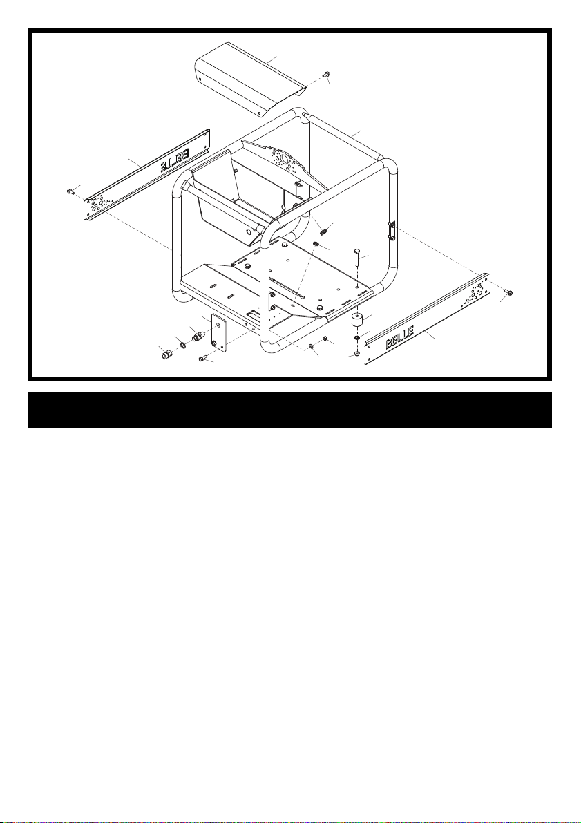
Pressure Washer Frame Assembly
1 995/03300SP ...... Frame ..................................................................... 1
2 995/99940S ......... Cover .....................................Orange .................... 1
2 995/99940R ........ Cover .....................................Red .......................... 1
3 996/99907S ......... Side Guard .............................Orange .................... 2
3 996/99907R ........ Side Guard .............................Red .......................... 2
4 7/8037 .................Screw .....................................M8 x 20 .................... 8
5 6/0284 ................. Adaptor ................................................................... 1
6 5/0007 ................. Seal ......................................................................... 1
7 6/0272 ................. Bulkhead ................................................................. 1
8 995/99941 ........... Plate ........................................................................ 1
9 7/8095 .................Screw .....................................M8 x 25 .................... 2
10 4/8006 ................. Washer ..................................M8 ...........................2
11 8/8008 ................. Nut .........................................M8 ........................... 2
12 8/10021 ............... Nut .........................................M12 ......................... 4
13 05.3.067 .............. Washer ..................................M12 .........................4
14 995/99939 ........... Spacer Boss ........................................................... 4
15 3/3020 ................. Grommet ................................................................. 1
16 7/10068 ............... Screw .....................................M10 x 60 .................. 4
17 3/3018 ................. Grommet ................................12.3 x 3.2mm ........... 1
14
4
13
11
12
10
3
24
Page 25
2
1
2-01
7
3
11
10
38
12
9
39
14
8
38
4
13
19
17
34
18
36
34
23
35
Engine, Gearbox & Pump Assembly
1 20/0139 ............... Engine ................................... Yanmar L100 ........... 1
2 23/00603 ............. Clamp ..................................................................... 1
3 995/03400 ........... Exhaust ................................................................... 1
4 6/1157 .................Pump & Gearbox Assy ........................................... 1
6 21/0377 ............... Key .......................................................................... 1
7 70/0325 ............... Battery ...................................12v ........................... 1
8 7/5021 .................Screw .....................................M5 x 25 .................... 1
9 70/0267 ............... Buzzer ....................................12v ........................... 1
10 8/5003 ................. Nut .........................................M8 ........................... 1
11 7/8037 ................. Screw .....................................M8 x 20 .................... 1
12 909/99949 ........... Clamp ..................................................................... 1
13 4/8006 ................. Washer ..................................M8 ...........................5
14 8/8008 ................. Nut .........................................M8 ........................... 1
15 7/8007 ................. Screw .....................................M8 x 35 .................... 4
16 4/8003 ................. Washer ..................................M8 ...........................4
17 6/0318 ................. Hosetail ................................................................... 1
18 6/0317 ................. Elbow ...................................................................... 1
19 6/5023 ................. Water Filter ............................................................. 1
20 4/8023 ................. Washer ..................................M8 ...........................2
21 21/0438 ............... AV Mount ................................................................ 2
22 4/8006 ................. Washer ..................................M8 ...........................2
23 8/8008 ................. Nut .........................................M8 ........................... 2
24 30/0090 ............... Hose ....................................................................... 2.8M
25 6/0282 ................. Thermal Relief Valve .............................................. 1
26 15.0.063 .............. Clip .......................................................................... 3
27 30/0090 ............... Hose ....................................................................... 2.8M
28 6/5025 ................. Deturgent Strainer Filter ......................................... 1
29 8/10006 ............... Nut .........................................M10 ......................... 4
30 4/1005 ................. Washer ..................................M10 .........................8
31 21.0.292 .............. AV Mount ................................................................ 2
32 4/1003 ................. Washer ..................................M10 .........................4
33 7/10003 ............... Screw .....................................M10 x 35 .................. 4
34 5/0086 ................. Seal ........................................ 3/4” ..........................2
35 6/0240 ................. Adaptor ...................................................................1
36 5/0002 ................. Seal ........................................ 1/2” ..........................1
37 7/10009 ............... Screw .....................................M10 .........................1
38 4/5002 ................. Washer ..................................M5 ...........................2
39 70/0267 ............... Spacer .................................................................... 1
40 3/7012 ................. P-Clip ...................................................................... 5
37
32
30
33
6
32
30
13
40
16
15
20
26
21
22
25
26
27
24
31
30
29
26
28
25
Page 26
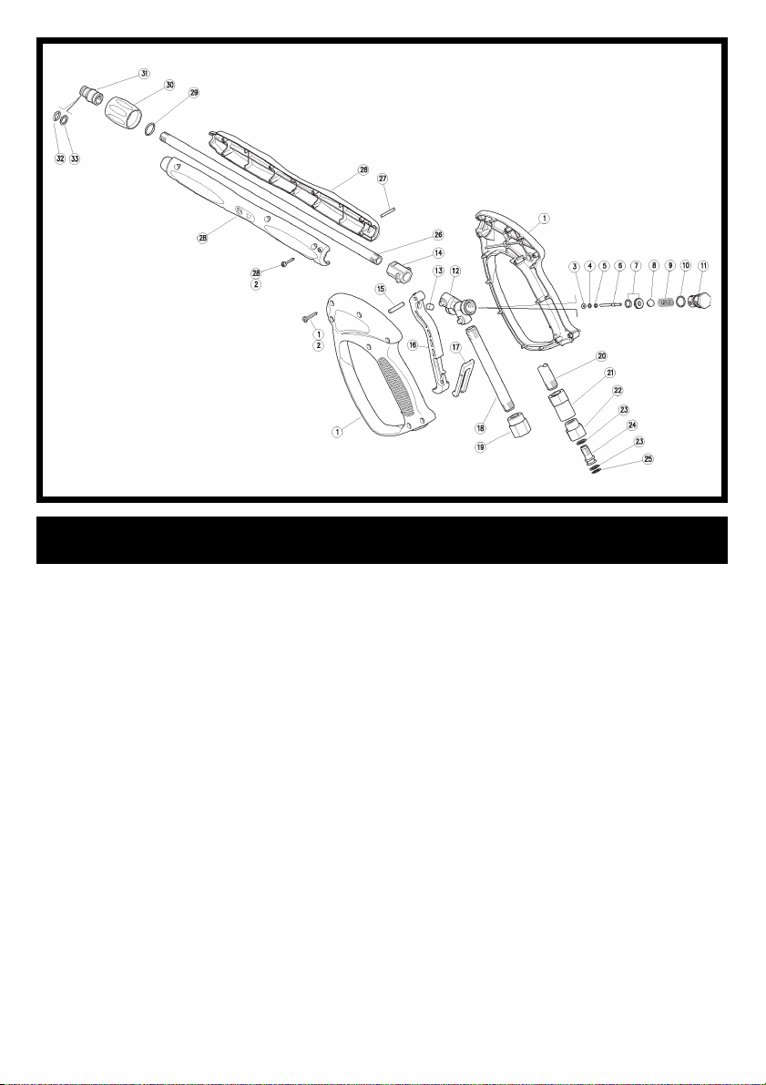
Lance Assembly - Handle End
1 30.1207.24 ..........Handle Case Kit ......................................................1
2 16.3077.00 .......... Screw ...................................................................... 13
3 10.4018.00 .......... Back-Up Ring .......................................................... 1
4 10.3165.00 .......... O-Ring .................................................................... 1
5 14.3511.00 .......... Washer ................................................................... 1
6 30.0704.51 .......... Piston ...................................................................... 1
7 30.1708.20 ..........Seal & O-Ring Kit ....................................................1
8 14.7448.00 .......... Ball .......................................................................... 1
9 30.2596.51 .......... Spring ..................................................................... 1
10 10.3020.02 .......... O-Ring .................................................................... 1
11 30.2595.31 .......... Spring Plug ............................................................. 1
12 30.1205.35 .......... Connector ...............................................................1
13 30.0675.84 .......... Stop Pin .................................................................. 1
14 30.4554.84 .......... Adapter ...................................................................1
15 30.2517.31 .......... Pin ........................................................................... 1
16 30.1204.84 .......... Trigger .................................................................... 1
17 30.1510.84 .......... Safety Latch ............................................................ 1
18 30.1203.66 .......... Tube ........................................................................ 1
19 30.1206.31 .......... Coupling .................................................................. 1
20 30.1221.66 .......... Tube ........................................................................ 1
21 30.1222.31 .......... Adaptor ...................................................................1
22 30.2019.31 .......... Coupling .................................................................. 1
23 10.4010.01 .......... Back-Up Ring .......................................................... 2
24 30.2017.51 .......... Pin ........................................................................... 1
25 10.3109.95 .......... O-Ring .................................................................... 1
26 30.1282.66 .......... Tube ........................................................................ 1
27 15.1046.00 .......... Pin ........................................................................... 1
28 40.4003.24 .......... Lance Casing Kit ..................................................... 1
29 26.0252.51 .......... Snap Ring ............................................................... 1
30 30.1286.22 .......... Nut .........................................M22 ......................... 1
31 26.0261.31 .......... pLUG .....................................14mm ......................1
32 10.3109.95 .......... O-Ring .................................................................... 1
33 10.4010.01 .......... Back-Up Ring .......................................................... 1
- 30.1554.24 .......... Repair Kit (Inc. Items 3, 4, 5, 6, 7, 8, 10, 23 & 25) .. 1
3-01
26
Page 27
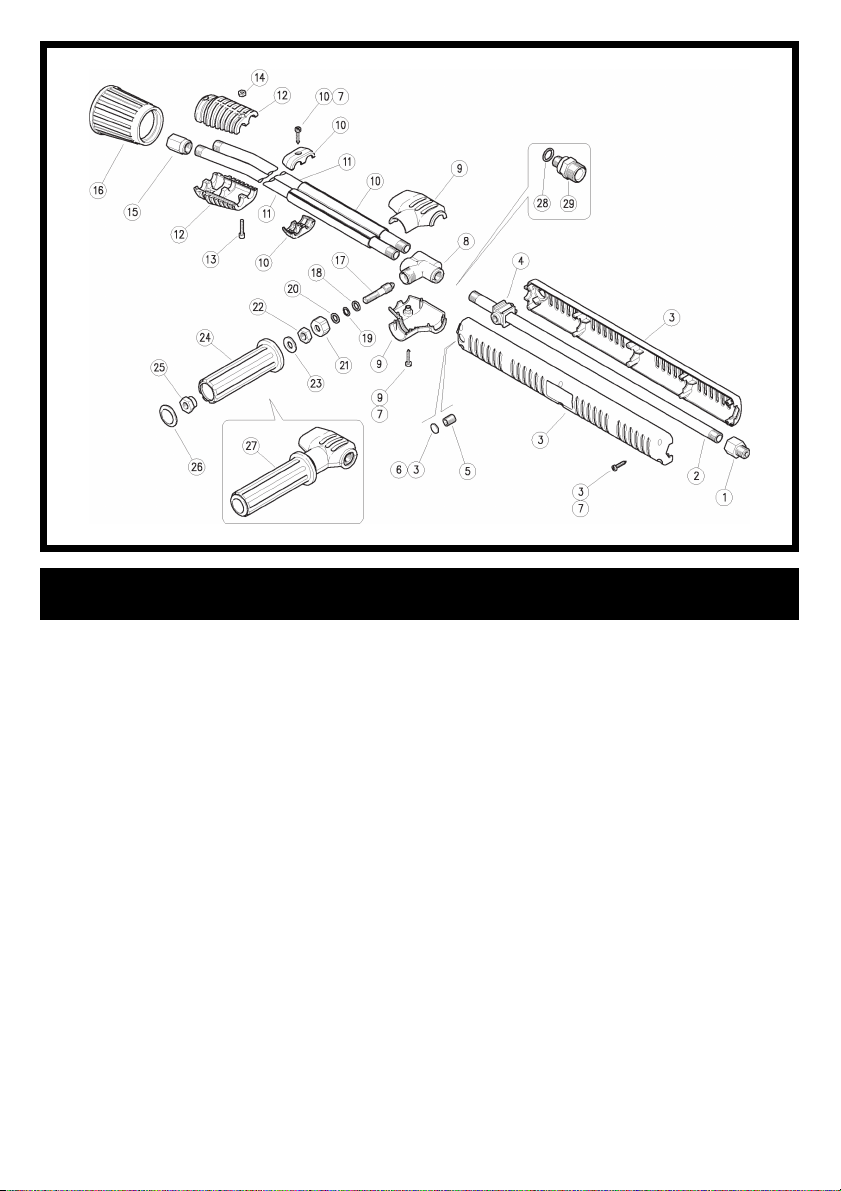
Lance Assembly - Nozzle End
1 40.5008.31 .......... Fitting ...................................................................... 1
2 40.0315.56 .......... Tube ........................................................................ 1
3 40.0308.24 ..........Upper Barrel Casing Kit .......................................... 1
4 40.0304.84 .......... Tube Fastener ........................................................1
5 16.2230.00 ..........Screw .....................................M10 x 8 .................... 1
6 40.0303.84 .......... Plug ......................................................................... 1
7 16.3077.00 .......... Screw ...................................................................... 8
8 41.0401.35 .......... Valve Housing ......................................................... 1
9 41.0424.24 ..........Lower Barrel Casing Kit .......................................... 1
10 41.0820.24 .......... Clamp Kit ................................................................ 1
11 40.7711.56 .......... Tube ........................................................................ 1
12 41.0416.84 .......... Lower Casing .......................................................... 2
13 16.1855.00 .......... Screw .....................................M4 x 20 .................... 2
14 11.4513.05 .......... Nut .........................................M4 ........................... 2
15 40.0007.61 .......... Nozzle Holder ......................................................... 2
16 41.0418.81 .......... Nozzle Protector ..................................................... 1
17 41.0405.51 .......... Shutter ....................................................................1
18 14.3643.00 .......... Washer ................................................................... 1
19 10.3170.00 .......... O-Ring .................................................................... 1
20 10.4020.00 .......... Back-Up Ring .......................................................... 1
21 41.0408.31 .......... Nut .........................................M18 ......................... 1
22 11.4574.00 .......... Nut .........................................M8 ........................... 1
23 14.3572.00 .......... Washer ................................................................... 1
24 41.0409.84 .......... Knob ....................................................................... 1
25 41.0410.31 .......... Nut .........................................M8 ........................... 1
26 41.0411.84 .......... Plug ......................................................................... 1
27 41.0906.24 .......... Valve Kit .................................................................. 1
28 14.3913.17 .......... Washer ................................................................... 1
29 26.1020.31 .......... Adaptor ...................................................................1
- 41.0422.24 .......... Spares Kit (Inc. Items 12, 13, 14 & 16) ................... 1
- 41.0423.24 .......... Spares Kit (Inc. Items 17 - 28) ................................ 1
3-02
27
Page 28
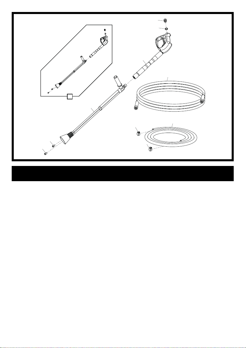
8
3-03
7
5
2
10
6
4
9
Lance & Hoses
1 34/0051 ............... Hose ....................................................................... 1
2 31/0146 ...............High Pressure Hose ................................................1
3 3/7066 ................. Jubilee Clip .............................................................2
4 6/0292 ................. Pressure Nozzle ....................08/180 ..................... 1
4 6/0291 .................Pressure Nozzle ....................13/230 & 15/250 ...... 1
5 995/02201 ........... Lance Trigger .......................................................... 1
6 995/02202 ........... Lance Barrel ...........................................................1
7 5/0007 ................. Seal ......................................................................... 1
8 6/0290 ................. Adaptor ................................................................... 1
9 6/0293 ................. Chemical Nozzle ..................................................... 1
10 995/03900SP ...... Lance Complete .....................08/180 ..................... 1
10 995/04000SP ...... Lance Complete .....................13/230 & 15/250 ......1
3
1
3
28
Page 29
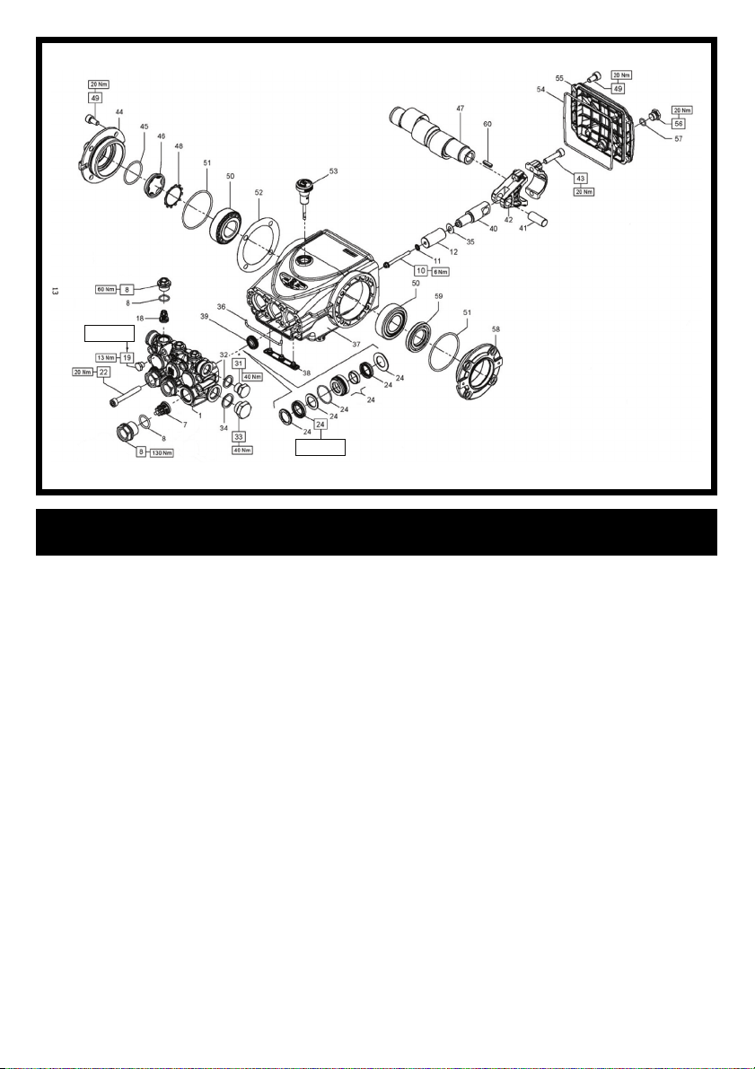
Loctite 542
Lubricate with
Grease
Pump Assembly
1 59.1208.41 ..................Pump Head................................................................ 1
7 36.7115.01 ..................Suction Valve Assembly ............................................ 3
8 E3B2515 KIT 292 ........Seals & Plugs Kit ....................................................... 1
10 99.1690.00 ..................Screw.....................................M5 x 55 ...................... 3
11 96.6905.00 ..................Washer .................................. M5 .............................. 3
12 59.0400.09 ..................Piston......................................................................... 1
18 36.7193.01 ..................Delivery Valve Assembly ........................................... 3
19 98.1967.00 ..................Plug .......................................1/8” x 8 .......................1
22 99.3175.00 ..................Screw.....................................M8 x 60 ...................... 8
31 98.2099.00 ..................Blanking Plug.........................3/8” x 13 ..................... 1
32 96.7380.00 ..................Seal Washer ..........................17.5 x 23 x 1.5 ............ 1
33 98.2179.00 ..................Blanking Plug.........................1/2” x 10 ..................... 1
34 96.7514.00 ..................Seal Washer ..........................21.5 x 27 x 1.5 ............ 1
35 96.6990.00 ..................Seal Washer ..........................7.5 x 23 x 0.5 .............. 1
36 59.2110.82 ..................Sponge Gasket ...................... Dia 3 x 10³ ................. 1
37 59.0100.22 ..................Pump Housing ........................................................... 1
38 58.2104.51 ..................Cover ......................................................................... 1
39 90.1565.50 ..................Ring .......................................15 x 24 x 5/7 ............... 3
40 59.0500.66 ..................Piston Guide .............................................................. 3
41 97.7399.00 ..................Dowel Pin ..............................14 x 34 ....................... 3
42 59.0300.01 ..................Complete Connecting Rod ........................................3
43 99.3099.00 ..................Screw.....................................M8 x 35 ...................... 6
44 47.1512.22 ..................Lateral Side Cover ..................................................... 1
45 90.3877.00 ..................O-Ring ....................................................................... 1
46 70.2118.01 ..................Oil Level Sight Glass ................................................. 1
47 59.0203.35 ..................Shaft .......................................................................... 1
48 90.0756.00 ..................Circlip.....................................Dia 45 ......................... 1
49 90.3039.00 ..................Screw.....................................M8 x 16 ...................... 8
50 91.8375.00 ..................Roller Bearing ............................................................ 2
51 90.3913.00 ..................O-Ring ....................................................................... 2
52 97.5680.00 ..................Gasket ...................................Dia 74.5 x 104 x 0.3 ... 1
53 98.2105.00 ..................Dipstick ..................................3/8” x 51 ..................... 1
54 90.3922.00 ..................O-Ring ...................................133.02 x 2.62 ............. 1
55 59.1600.22 ..................Rear Cover ................................................................ 1
56 98.2042.50 ..................Blanking Plug............................................................. 1
57 90.3585.00 ..................O-Ring ...................................10.8 x 1.78 ................. 1
58 47.1510.22 ..................Lateral Cover ............................................................. 1
59 90.1648.00 ..................Ring .......................................30 x 55 x 4 .................. 1
60 91.4685.00 ..................Key ............................................................................ 1
4-01
29
Page 30
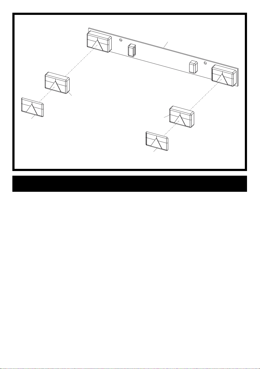
5-01
1
2
4
Lightboard Assembly Option
1 70/0370 .......................Lightboard Assembly ................................................. 1
2 995/99959 ...................Lamp Assembly ..................... Left Hand .................... 1
3 995/99964 ...................Lamp Assembly ..................... Right Hand ................. 1
4 995/99960 ...................Lens ....................................... Left Hand .................... 1
5 995/99965 ...................Lens ....................................... Right Hand ................. 1
3
5
30
Page 31
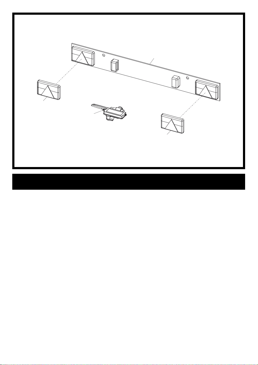
3
2
LED Lightboard Assembly Option
1 70/0368 .......................LED Lightboard.......................................................... 1
2 70/0369 .......................Plug & Play Smart Load Relay .................................. 1
3 995/99966 ...................LED Lamp Assembly ............. Left Hand .................... 1
4 995/99967 ...................LED Lamp Assembly ............. Right Hand ................. 1
5-02
1
4
31
Page 32
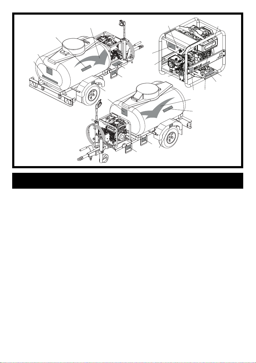
4
17
3
9
6-01
2
1
7
2
Decals
1 800/99223 ...................Decal ..............................Web Address ..................... 1
2 800/99218 ...................Decal ..............................Logo (148mm) ................... 2
3 800/99221 ...................Decal ..............................BWX 15/250 Large ............ 2
4 800/99219 ...................Decal ..............................Wings LH ........................... 1
5 800/99220 ...................Decal ..............................Wings RH .......................... 1
6 800/99242 ...................Decal ..............................Forklift ................................ 4
7 800/99222 ...................Decal ..............................Tyre Pressure .................... 2
8 800/99318 ...................Decal ..............................Logo (60mm) ..................... 2
9 800/99224 ...................Decal ..............................BWX 15/250 Large ............ 2
10 800/99355 ...................Decal ..............................109 dB(A) .......................... 1
11 800/99377 ...................Decal ..............................Safety Insructions .............. 1
12 19.0.373 ......................Decal ..............................4 in 1 Safety ......................1
13 800/99352 ...................Decal ..............................High Pressure Outlet ......... 1
14 800/99243 ...................Decal ..............................Drain Taps ......................... 1
15 800/99678 ...................Decal ..............................Ignition ............................... 1
16 800/99262 ...................Decal ..............................Operating Instructions ....... 1
17 800/21250 ...................Decal ..............................Iginition Warning Light ....... 1
16
14
6
15
13
12
11
108
5
4
6
6
7
32
Page 33

33
Page 34

ALTRAD BELLE
Sheen, Nr. Buxton, Derbyshire, SK17 0EU, GB
Tel. +44 (0)1298 84606 - Fax +44 (0)1298 84722 - Email: [email protected]
www.Altrad-Belle.com
34
 Loading...