

Page 1
us a/Ca na da
u.s.a. O nL Y
Combitherm®
CombiTouch® Gas
TECHNICAL SERVICE
MANUAL
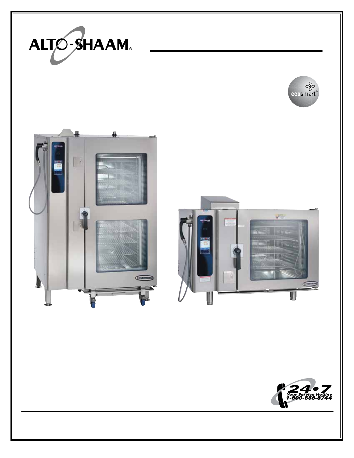
20.20esG CombiTouch 7.14esG CombiTouch
W164 N9221 Water Street • P.O. Box 450 • Menomonee Falls, Wisconsin 53052-0450 USA
PHONE: 262.251.3800 • 800.558.8744
p ri n te d i n u . s. a .
www.alto-shaam.com
FAX: 262.251.7067 • 800.329.8744
M N-2 92 48 • 0 5 /11
Page 2

How to Use this Technical Service Manual
This manual has been compiled as a complete resource for a technician working on Combitherm CombiTouch Gas models.
It includes necessary product information and drawings, along with helpful troubleshooting procedures.
Navigation
On this document, starting with the Main Table of Contents on the following page, you may click on any item that has a
page number and quickly jump to the information you need. Note that you may Return to the Main Table of Contents from
the bottom of any Section Contents page.
Printing
From this document, you may print the Current Page or any range of pages.
Here’s a tip: Because printers vary in their capacity to handle large drawings, make a test print of one of the Wiring
Diagrams before printing the model’s section.
C O MB I T H E RM C O M BI TO U C H G A S TE C Hn I CA l S E Rv IC E M A nU A l • i
Page 3
Table of ConTenTs
HOW TO USE THIS TECHNICAL
SERVICE MANUAL
TABLE OF CONTENTS ii
COMBITOUCH CONTROL INTRODUCTION 1
CONTROL PANEL IDENTIFICATION 2
FACTORY DEFAULT SETTINGS 6
SAFETY PRECAUTIONS 7
OPERATION MODES
Steam 8
Combination 10
Convection 12
Retherm 14
Core Temperature Probe 16
Core Temperature - Delta-T 17
AUXILIARY FUNCTIONS
Preheating 18
Gold-n-Brown™ 18
Cool-Down Feature 18
Reduced Fan Speed 19
Reduced Power 19
Multi-shelf Timer 19
Steam Injection 19
CombiSmoker™ Procedures 20
PREPROGRAMMED RECIPES
Using Preprogrammed Recipes 22
Recipe Programming 23
Preprogrammed Bakery Recipes 24
Preprogrammed Convenience
Product Recipes
Preprogrammed Fish & Seafood Recipes 27
Preprogrammed Meat Recipes 28
Preprogrammed Miscellaneous Recipes 30
Preprogrammed Poultry Recipes 31
Preprogrammed Vegetable Recipes 32
i
25
HACCP ACCESS 34
CLEANING & MAINTENANCE
Cleaning Menus 35
Preventive Maintenance 36
Food Trolley Cleaning 36
Protecting Stainless Steel Surfaces 37
Cleaning Agents 37
Cleaning Materials 37
Daily Gasket Cleaning 38
Probe Usage and Cleaning 38
Daily Oven Cleaning 38
Daily Steam Generator Flush 38
Regular Decalcification 38
Monthly Cleaning 38
Combitherm Oven Cleaner Precautions 39
Steam Generator Flush 39
Decalcification 39
TROUBLE SHOOTING
Emergency Operation Mode 40
Error Codes 42
COMBITHERM PARTS
Service Parts 47
COMBITHERM WIRING DIAGRAMS
Index 78
C O MB I T H E RM C O M BI TO U C H G A S TE C Hn I CA l S E Rv IC E M A nU A l • ii
Page 4

INTRODUCTION
COMBITOUCH® CONTROL
The Combitherm CombiTouch control features a simple,
graphics-based control panel that commands all the
oven functions. Access up to 250 of your recipes that
are identied by your own uploaded pictures. Manual
cooking by time and temperature also are easily done with
the CombiTouch control.
Intuitive interface - The Alto-Shaam CombiTouch offers
a simple interface that commands
all of the Combitherm’s cooking
functions. As the name implies, it
is fully operable by touch.
Graphic controls - The highly
visual graphic-based control
overcomes language barriers while
the simple, logical procedures
ensure that correct steps are
followed every time.
STEAM MODE
COMBINATION MODE
CONVECTION MODE
An excellent memory - Access
up to 250 of your recipes that are
identied by your own uploaded
pictures. The Combitherm
with CombiTouch also comes
standard with more than 100 preprogrammed recipes and photos,
covering most commonly prepared food items.
RETHERM MODE
Standard HACCP - The Combitherm with CombiTouch
includes a standard downloadable HACCP function.
Six levels of Gold-n-Brown™ - Six precise and consistent
browning levels are available with the CombiTouch. The
exclusive Gold-n-Brown feature gives the operator the
ability to achieve the ideal cooking environment for the
ideal nish.
Superior baking - The new two-speed reversing fan
provides excellent and consistent
baking results. A moisture
injection feature provides perfect
sheen and crust on breads and
pastry items.
Multi-shelf timers - Track cooking
time of either seven or 10 different
food items (depending on oven
size) in the same oven with multishelf timers. Time is tracked in
minutes and seconds.
On-board diagnostics - The
CombiTouch system includes
on-board diagnostic functionality
with results displayed right on the
touch screen.
Reduced energy setting - CombiTouch features
an interactive control display with reduced energy setting.
Powerful tool - The CombiTouch control plays an important part in our continuous improvement process. New features
and abilities can be uploaded to your oven as they become available. Simply call our Service Department for assistance.
ECOSMART® TECHNOLOGY
The Alto-Shaam CombiTouch
Combitherm combination oven/steamer
employs Ecosmart operating efficiencies
in the design and application of all
operating and programming functions.
Ecosmart operational characteristics include the use
of a water barrier to close the oven compartment to
the outside air. While maintaining a non-pressurized
atmosphere, the primary purpose of the Ecosmart
system is to prevent the steam and heat generated
within the oven compartment from freely escaping
to the outside.
The Ecosmart design displaces the air within the
cooking compartment and achieves a higher level
of steam saturation that offers quick-steaming at
temperatures above 212°F (100°C).
This guide is provided as an operational aid with
step-by-step instructions of the basic functions of
the Combitherm oven, along with the many other
additional features of the control.
1
Page 5

OPERATING INSTRUCTIONS
CONTROL PANEL IDENTIFICATION
RECIPE MENU
When the oven is powered on, the Recipe Menu is the
rst screen you will see. This allows quick access to
begin the cooking process. As a rst time user, you
may want to personalize your CombiOven to reect the
settings you are most comfortable with.
Return to Previous Screen - Press the red arrow to
access the Main Menu screen.
1. Cleaning Mode
Four (4) cleaning levels are available: rinse, light,
normal, and heavy-duty cleaning.
2. Download/Upload Files
Download all preprogrammed recipes (factory default
MAIN MENU
SCREEN
1 CLEANING MODE
2 DOWNLOAD/UPLOAD FILES
3 SETTINGS
4 SERVICE MODE
(PASSWORD PROTECTED)
and user-programmed) and photos to a USB memory
stick. See below for more information.
3. Settings and HACCP Access
Change factory default settings. See next page for
more information.
4. Service Mode (password protected)
This mode is only available to qualied
service technicians.
UPLOAD/DOWNLOAD SCREEN
1 DOWNLOAD RECIPES
3 ADD ALL RECIPES
4 UPLOAD ALL PHOTOS
6 ADD SOUNDS
2 UPLOAD
RECIPES
5 DELETE
PHOTOS
2
1. Copy Recipes to Oven
Copy all recipes from USB memory stick
to oven. This will replace and overwrite
existing recipes.
2. Copy Recipes from Oven
Copy all recipes from oven to USB memory stick
3. Add Recipes to Oven
Copy all recipes from USB memory stick to the
oven. This will add the recipes to the beginning
of the existing recipe list.
4. Copy Photos to Oven
Upload photo les from a USB memory stick to
oven for user-programmed recipes
5. Delete Photos on Oven
Delete specic photo les used in the
programmed recipes on oven
6. Add Sounds
Page 6

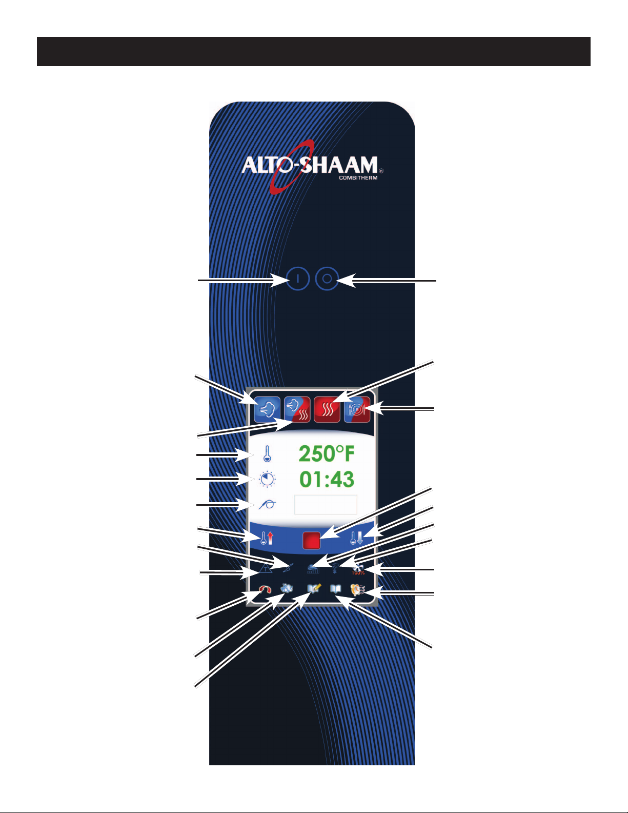
CONTROL PANEL IDENTIFICATION
1 FAHRENHEIT OR CELSIUS
3 NUMBER OF SHELVES FOR
MULTI-SHELF TIMER
5 DEFAULT MEMO
OPERATING INSTRUCTIONS
OPERATING INSTRUCTIONS
SETTINGS SCREEN
2 TIMER FORMAT
4 MULTI-SHELF TIMER FORMAT
6 DISPLAY SETTINGS
7 RETURN TO PREVIOUS SCREEN
1. Fahrenheit or Celsius Function - Choose
temperature format.
2. Timer Format - Display time as
HOURS:MINUTES:SECONDS or HOURS:MINUTES.
3. Multi-shelf Timer Number of Shelves -
Choose the default number shelves in the oven to be
used by the multi-shelf timer.
4. Multi-shelf Timer Format - Display
MINUTES:SECONDS or MINUTES only in timer.
5. Default Memo - Reverts all settings to factory
defaults. Clears all user-input times and temperatures
except those in programmed recipes.
6. Display Settings - Choose to display text or
image assigned to a recipe.
8 FORWARD TO NEXT SCREEN
7. Return to Previous Screen - Return to previous
screen when nished adjusting settings.
8. Forward to Next Screen - Advance to next screen to
review additional settings.
9. Sound/Alarm Settings - Change alarm sounds
and volume.
10. Touchscreen Brightness - Adjust brightness
of Touchscreen.
11. Lock/Unlock Recipes - Password protect
preprogrammed recipes.
12. Set/Change Date & Time - Set or change oven
time and date settings.
13. HACCP Data - Review data collected or
download data to a USB drive.
9 SOUND SETTINGS
11 LOCK/UNLOCK RECIPES
13 HACCP DATA
10 TOUCH SCREEN BRIGHTNESS
12 SET/CHANGE DATE & TIME
3
Page 7
OPERATING INSTRUCTIONS
CONTROL PANEL IDENTIFICATION
1 POWER ON KEY
2 STEAM MODE
3 COMBINATION MODE
6 TEMPERATURE
7 TIME
8 CORE TEMPERATURE
9 PREHEAT
12 REDUCED POWER MODE
22 DELTA-T (ONLY VISIBLE
IN CERTAIN MODES)
1 POWER OFF KEY
4 CONVECTION MODE
5 RETHERM MODE
11 START/STOP ICON
10 COOL DOWN
13 GOLD-N-BROWN MODE
14 SMOKING MODE (OPTIONAL)
15 FAN SPEED
20 MULTI-SHELF TIMER
16 GO TO PREVIOUS SCREEN
17 CLEANING MODE
18 ADD RECIPE
19 FIND RECIPE
4
Page 8

OPERATING INSTRUCTIONS
CONTROL PANEL IDENTIFICATION
MAIN MENU ICONS
1. Power ON key
Activates power to the oven and automatically lls the
steam generator equipped models with water that will
heat to a stand-by mode temperature of 188°F (77°C).
2. Steam Mode
The oven will operate in the steam mode at a
temperature range of 85°F to 250°F (30°C to 121°C).
• Automatic steaming at 212°F (100°C) factory-set
default.
• Quick steaming between 213°F and 250°F (101°C
and 121°C).
• Low temperature steaming between 85°F and 211°F
(29°C and 99°C).
3. Combination Mode
Selection key for cooking with a combination of steam
and convection heat. Can be set between 212°F to 485°F
(100°C and 252°C).
4. Convection Mode
Selection key for convection cooking without steam at a
temperature range of 85°F to 485°F (29°C to 252°C).
5. Retherm Mode
Food rethermalization or reheating mode will operate
with automatic steam injection at a temperature range
of 245°F to 320°F (120°C to 160°C).
6. Temperature
Used to set the required cooking temperature, to recall
the set cooking temperature, or to check the actual oven
temperature.
11. Start/Stop
Initiates all cooking mode functions and programmed
procedures stored in memory. Stops an activated
cooking mode or programmed procedure currently
in progress.
AUXILIARY FUNCTION ICONS
12. Reduced Power Mode
Used to reduce kitchen power peaks and
energy consumption.
13.
Gold-N-Brown Mode
This indicator will illuminate when the browning
function is set by the operator in a timed or
programmed cooking cycle in any mode. Level 1
provides least amount of browning, level 6 the most.
14. Smoking Mode (optional)
This indicator will illuminate when the smoking
function is set by the operator in a timer, probe or
programmed cooking cycle in either convection mode
or combination mode.
15. Fan Speed
This indicator will illuminate whenever the operator
sets a reduced fan speed to protect products affected
by high-velocity air movement.
16. Return to Previous Menu
17. Cleaning Mode
Four (4) cleaning levels are available: rinse, light,
normal, and heavy-duty cleaning.
7. Time
Used to set the required cooking time or recall the set
cooking time.
8. Core Temperature
Used to set the required internal product temperature,
to recall the internal product temperature set by the
operator, or to display the current internal temperature
of the product.
9. Preheat Mode
Preheats the oven cavity to a temperature set by user.
10. Cool Down Mode
Lowers temperature of the oven cavity at an
accelerated pace to temperature set by user.
18. Add Recipe
Used to create, change, duplicate, and delete
programmed menus.
19. Find Recipe
Access a menu list of all stored cooking programs.
20. Multi-shelf Timer
Use separate timers for one or more shelves in the
oven compartment.
21. Steam Injection (not shown on illustration)
Press to add moisture in any cooking mode. Steam will
inject into the cavity as long as the icon is touched.
22. Delta-T Core Temperature (only visible in certain
modes) Cook by probe. Mode automatically adjusts
cooking temperature in proportion to the internal
temperature of the product.
5
Page 9

OPERATING INSTRUCTIONS
COMBITOUCH FACTORY DEFAULT SETTINGS
COOKING MODE OVEN TEMPERATURE CORE TEMPERATURE COOKING TIME
Steam
Combination Steam
Convection
Retherm
Preheat
Cool Down
Delta T
212°F
(100°C)
350°F
(175C)
350°F
(175°C)
275°F
(135°C)
350°F
(175°C)
212°F
(100°C)
120°F
(50°C)
160°F
(70°C)
160°F
(70°C)
160°F
(70°C)
160°F
(70°C)
N/A N/A
N/A N/A
170°F
(75°C)
25 minutes
60 minutes
30 minutes
5 minutes
N/A
6
Page 10
OPERATING INSTRUCTIONS
IMPORTANT SAFETY PRECAUTIONS
NOTE: Automatic steam venting is a standard safety
feature built into all Combitherm oven models.
This feature vents all steam from the oven
compartment immediately before cooking time
expires or set probe temperature is reached.
This function is provided in all programmed
and timed production when operating in any
Steam, Combination, Convection, and Retherm
cooking mode. Automatic steam venting does
not function if the oven door is opened before
time expires or when the oven has been set to
continuous operation.
DANGER
AT NO TIME SHOULD THE INTERIOR
OR EXTERIOR BE STEAM CLEANED,
HOSED DOWN, OR FLOODED WITH
WATER OR LIQUID SOLUTION OF
ANY KIND. DO NOT USE WATER JET
TO CLEAN.
SEVERE DAMAGE OR
ELECTRICAL HAZARD
COULD RESULT.
WARRANTY BECOMES VOID IF
APPLIANCE IS FLOODED
NOTE: Use authorized combitherm oven cleaner only.
unauthorized cleaning agents may discolor or
harm interior surfaces of the oven. Read and
understand label and material safety data sheet
before using the oven cleaner.
FOR OPERATOR SAFETY
NOTE AND OBSERVE ALL SAFETY PRECAUTIONS
LOCATED THROUGHOUT THIS GUIDE
HOT STEAM CAUSES BURNS
ROTATE THE DOOR HANDLE TO THE FIRST OPEN
ROTATION POSITION ONLY. WAIT UNTIL THE
STEAM IS VENTED BEFORE FULLY OPENING THE
DOOR.
CAUTION
METAL PARTS OF THIS EQUIPMENT
BECOME EXTREMELY HOT WHEN
IN OPERATION. TO AVOID BURNS,
ALWAYS USE HAND PROTECTION
WHEN OPERATING THIS APPLIANCE.
DO NOT HANDLE PANS CONTAINING LIQUID
OR SEMILIQUID PRODUCTS POSITIONED
ABOVE THE EYE LEVEL OF THE OPERATOR.
SUCH PRODUCTS CAN SCALD AND CAUSE
SERIOUS INJURY.
DO NOT USE THE ATTACHED HAND-HELD
HOSE TO SPRAY ANYTHING OTHER THAN
THE INTERIOR OF THE COMBITHERM OVEN
COMPARTMENT.
DO NOT USE THE SPRAY HOSE ON
THE SURFACE OF A HOT COOKING
COMPARTMENT. ALLOW THE OVEN TO COOL
TO A MINIMUM OF 150°F (66°C).
7
Page 11

OPERATING INSTRUCTIONS
STEAM MODE
The Steam mode provides the operator with the ability
to steam, poach, or blanch. This mode will automatically
steam at the boiling point of water; quick-steam above the
boiling point for faster cooking results; or low temperature
steam, below the boiling point, for more delicate products
such as pâté, mousse, seafood, or custard.
PRESS ON BUTTON TO POWER OVEN ON.
PRESS THE STEAM MODE ICON.
Automatic Steam temperature of 212°F (100°C)
will appear in the display. The last set time or
oven control default setting for time will appear
in the display.
PRESS THE START ICON TO STEAM AT THE
DISPLAYED SETTINGS.
TO CHANGE THE DISPLAYED SETTINGS:
TOUCH THE DISPLAYED TEMPERATURE.
The cooking temperature will appear at the top of
the temperature selection window. Type in desired
temperature or use up and down arrows to adjust
temperature. When nished, touch the green checkmark
key to conrm change.
• Automatic Steaming 212°F (100°C)
• Quick Steaming 213°F to 250°F (101°C to 121°C)
• Low Temperature Steaming 85°F to 211°F (29°C to 99°C)
TO COOK BY PRODUCT CORE TEMPERATURE:
TOUCH THE PROBE ICON.
The previously set core temperature or oven control
default setting will appear highlighted within the oven
display. Touch the displayed core temperature. The
internal product core temperature will appear at the top
of the temperature selection window. Type in desired
internal product core temperature or use up and down
arrows to adjust temperature. When nished, touch the
green checkmark key to conrm change.
Attach removable probe before activating core
temperature function, and insert into product.
PRESS THE GREEN START ARROW ICON TO
BEGIN COOKING IN STEAM MODE.
• The temperature and remaining cooking time will
appear in the display.
• If cooking by probe, the actual internal product
temperature will appear next to the icon during
operation. To change the set value for core temperature,
press the temperature next to the icon and make
changes as required.
When the cooking time has expired or the operator set
internal temperature has been reached, an alarm will
sound indicating the end of the operating mode.
• To stop the buzzer, press the red stop key or open
the oven door.
TO COOK BY TIME:
TOUCH THE DISPLAYED TIME.
The cooking time will appear at the top the time selection
window. Type in desired time period or use up and down
arrows to adjust time. When nished, touch the green
checkmark key to conrm change.
Or, to set Continuous Operation mode, type in --:-- and
touch the green checkmark key to conrm.
TO STOP COOKING PROGRAM AT ANY TIME,
PRESS RED STOP BUTTON.
8
Page 12

OPERATING INSTRUCTIONS
STEAM MODE CHEF OPERATING TIPS
This mode will steam a full or partial load of a single
product, or multiple products without transfer of avors.
When steaming multiple products, however, individual
product cooking times must be taken into consideration.
STEAM
Perforated, 2-1/2" deep pans (65mm)
are particularly suitable for use in
this program mode. These pans will
provide a shorter cooking time and
will prevent product over-cooking at
the bottom of the pan.
Separate ice-encrusted vegetables
before steaming to assure
even cooking.
A variety of products can be steamed
at the same time but attention must
be paid to the different cooking times
required for each food product.
HIGH TEMP STEAMING
High temperature steaming is
suitable for hearty, root-type
vegetables such as potatoes, legumes,
and cabbage.
High temperature steaming
provides a cooking time which is
approximately 10-percent shorter
than the regular steam mode
temperature of 212°F (100°C).
Set the steam cooking temperature
between 221°F (105°C) and 230°F
(110°C) for small loads and between
230°F (110°C) and 250°F (121°C) for
full loads.
The non-pressurized atmosphere of the Combitherm
also provides the ability to open the door during the
steam mode in order to monitor products more closely
throughout the steaming process.
LOW TEMP STEAM
The low temperature steam mode
will function whenever the oven
compartment temperature is below
212°F (100°C).
It will take longer to steam products
using the low temperature
steam mode.
Steaming sausages in low
temperature steam prevents cracked
or peeling skins.
Use low temperature steam for
delicate foods such as shrimp, sh,
seafood, and crème caramel.
For best results, low temperature
steam all delicate food items at a
temperature of 210°F (99°C)
or below.
9
Page 13

OPERATING INSTRUCTIONS
COMBINATION MODE
The Combination mode will prove to be the most versatile
and widely used mode the Combitherm oven has to offer.
It will produce the best possible results on the widest
variety of products — all within the shortest period of
time. The unique control function of this mode enables
the operator to roast or bake with a combination of steam
and convection heat. In addition to shorter cooking times,
this combination of steam and heat offers less product
shrinkage and more moisture retention than obtained in a
standard convection oven.
PRESS ON BUTTON TO POWER OVEN ON.
PRESS THE COMBINATION MODE ICON.
The last set values or oven control default setting for
temperature and time will appear in the display.
PRESS THE START ICON TO COOK AT THE
DISPLAYED SETTINGS.
TO CHANGE THE DISPLAYED SETTINGS:
TOUCH THE DISPLAYED TEMPERATURE.
The cooking temperature will appear at the top of
the temperature selection window. Type in desired
temperature or use up and down arrows to adjust
temperature. When nished, touch the green checkmark
key to conrm change.
• Cooking temperature range: 212 to 485 °F (100 to 252°C)
TO COOK BY TIME:
TOUCH THE DISPLAYED TIME.
TO COOK BY PRODUCT CORE TEMPERATURE:
TOUCH THE PROBE ICON.
The previously set core temperature or oven control
default setting will appear highlighted within the oven
display. Touch the displayed core temperature. The
internal product core temperature will appear at the top
of the temperature selection window. Type in desired
internal product core temperature or use up and down
arrows to adjust temperature. When nished, touch the
green checkmark key to conrm change.
Attach removable probe before activating core
temperature function, and insert into product.
PRESS THE GREEN START ARROW ICON TO
BEGIN COOKING IN COMBINATION MODE.
• The temperature and remaining cooking time will
appear in the display.
• If cooking by probe, the actual internal product
temperature will appear next to the icon during
operation. To change the set value for core temperature,
press the temperature next to the icon and make
changes as required.
PRESS FOR STEAM INJECTION AT ANY TIME
DURING COOKING. Steam will inject into the
cavity as long as the icon is touched.
When the cooking time has expired or the operator set
internal temperature has been reached, an alarm will
sound indicating the end of the operating mode.
• To stop the buzzer, press the red stop key or open
the oven door.
The cooking time will appear at the top the time selection
window. Type in desired time period or use up and down
arrows to adjust time. When nished, touch the green
checkmark key to conrm change.
Or, to set Continuous Operation mode, type in --:-- and
touch the green checkmark key to conrm.
10
TO STOP COOKING PROGRAM AT ANY TIME,
PRESS RED STOP BUTTON.
Page 14

OPERATING INSTRUCTIONS
COMBINATION MODE CHEF OPERATING TIPS
The Combination mode injects the optimum amount of
steam automatically. There is no need to select moisture
levels. Foods do not dry out. Flavors are retained with no
transfer of avors when mixing product loads.
Due to automatic steam adjustment, the door can be
opened at any time during a cooking operation. Be
certain to observe the safety warning when opening the
oven door.
The Combination mode is particularly efcient when
used for baking, broiling, grilling, stewing, braising,
and roasting.
When using the Combination mode, cooking temperatures
can be reduced 10- to 20-percent below the temperatures
used for conventional cooking methods.
Cooking time will be reduced approximately 40-percent
when cooking at the same temperature used for
convection oven cooking and up to 50- to 60-percent less
time when cooking at the same temperature used for a
conventional oven.
Food browning in the Combitherm begins at a cooking
temperature of approximately 250°F (120°C).
A higher cooking temperature results in heavier browning
but also results in greater product weight loss. To achieve
additional browning use the Moisture Vent Key or set
Gold-n-Brown into the product procedure. Gold-n-Brown
is particularly useful for adding color to high moisture
products such as chicken and other poultry items or
for additional browning of full loads and other
moist products.
The Combination mode provides even browning without
the necessity to turn the pans.
For more even cooking, do not cook in pans deeper than
4" (100mm).
11
Page 15

OPERATING INSTRUCTIONS
CONVECTION MODE
The Convection mode operates with hot circulated air
within a temperature range of 85° to 485°F (29 to 252°C).
For many applications, better results may be
achieved with the Combination mode; therefore, the
operator may want to consider using the Convection
mode on a more limited basis.
PRESS ON BUTTON TO POWER OVEN ON.
PRESS THE CONVECTION MODE ICON.
The last set values or oven control default setting for
temperature and time will appear in the display.
PRESS THE START ICON TO COOK AT THE
DISPLAYED SETTINGS.
TO CHANGE THE DISPLAYED SETTINGS:
TOUCH THE DISPLAYED TEMPERATURE.
The cooking temperature will appear at the top of
the temperature selection window. Type in desired
temperature or use up and down arrows to adjust
temperature. When nished, touch the green checkmark
key to conrm change.
• Cooking temperature range: 85 to 485 °F (29 to 252°C)
TO COOK BY TIME:
TO COOK BY PRODUCT CORE TEMPERATURE:
TOUCH THE PROBE ICON.
The previously set core temperature or oven control
default setting will appear highlighted within the oven
display. Touch the displayed core temperature. The
internal product core temperature will appear at the top
of the temperature selection window. Type in desired
internal product core temperature or use up and down
arrows to adjust temperature. When nished, touch the
green checkmark key
Attach removable probe before activating core
temperature function, and insert into product.
PRESS THE GREEN START ARROW ICON TO
BEGIN COOKING IN COMBINATION MODE.
• The temperature and remaining cooking time will
appear in the display.
• If cooking by probe, the actual internal product
temperature will appear next to the icon during
operation. To change the set value for core temperature,
press the temperature next to the icon and make
changes as required.
PRESS FOR STEAM INJECTION AT ANY TIME
DURING COOKING. Steam will inject into the
cavity as long as the icon is touched.
to conrm change.
TOUCH THE DISPLAYED TIME.
The cooking time will appear at the top the time selection
window. Type in desired time period or use up and down
arrows to adjust time. When nished, touch the green
checkmark key to conrm change.
Or, to set Continuous Operation mode, type in --:-- and
touch the green checkmark key to conrm.
When the cooking time has expired or the operator set
internal temperature has been reached, an alarm will
sound indicating the end of the operating mode.
• To stop the buzzer, press the red stop key or open
the oven door.
TO STOP COOKING PROGRAM AT ANY TIME,
PRESS RED STOP BUTTON.
12
Page 16

OPERATING INSTRUCTIONS
CONVECTION MODE CHEF OPERATING TIPS
The Convection Mode can be used to roast or bake
products needing very short cooking times or for high
moisture products such as mufns, cakes, and cookies, or
for browning the surface of the product.
The Convection mode works best with foods containing
little moisture or for very moist food which require a
dryer nished product.
For baking, preheat the Combitherm at a temperature of
325°F to 375°F (163°C to 191°C). Once preheated, reset the
temperature as required.
A higher cooking temperature results in heavier browning
but also results in greater product weight loss. To achieve
additional browning use the Moisture Vent Key or set the
Browning Feature into the product procedure.
13
Page 17

OPERATING INSTRUCTIONS
RETHERM MODE
The Retherm mode operates with hot circulated air within
a temperature range of 245° to 320°F (120° to 160°C).
PRESS ON BUTTON TO POWER OVEN ON.
PRESS THE RETHERM MODE ICON.
The last set values or oven control default setting for
temperature and time will appear in the display.
PRESS THE START ICON TO COOK AT THE
DISPLAYED SETTINGS.
TO CHANGE THE DISPLAYED SETTINGS:
TOUCH THE DISPLAYED TEMPERATURE.
The cooking temperature will appear at the top of
the temperature selection window. Type in desired
temperature or use up and down arrows to adjust
temperature. When nished, touch the green checkmark
key to conrm change.
• Cooking temperature range: 245 to 320 °F (120 to 160°C)
TO COOK BY TIME:
TO COOK BY PRODUCT CORE TEMPERATURE:
TOUCH THE PROBE ICON.
The previously set core temperature or oven control
default setting will appear highlighted within the oven
display. Touch the displayed core temperature. The
internal product core temperature will appear at the top
of the temperature selection window. Type in desired
internal product core temperature or use up and down
arrows to adjust temperature. When nished, touch the
green checkmark key
Attach removable probe before activating core
temperature function, and insert into product.
PRESS THE GREEN START ARROW ICON TO
BEGIN COOKING IN COMBINATION MODE.
• The temperature and remaining cooking time will
appear in the display.
• If cooking by probe, the actual internal product
temperature will appear next to the icon during
operation. To change the set value for core temperature,
press the temperature next to the icon and make
changes as required.
to conrm change.
TOUCH THE DISPLAYED TIME.
The cooking time will appear at the top the time selection
window. Type in desired time period or use up and down
arrows to adjust time. When nished, touch the green
checkmark key to conrm change.
Or, to set Continuous Operation mode, type in --:-- and
touch the green checkmark key to conrm.
PRESS FOR STEAM INJECTION AT ANY TIME
DURING COOKING. Steam will inject into the
cavity as long as the icon is touched.
When the cooking time has expired or the operator set
internal temperature has been reached, an alarm will
sound indicating the end of the operating mode.
• To stop the buzzer, press the red stop key or open
the oven door.
TO STOP COOKING PROGRAM AT ANY TIME,
PRESS RED STOP BUTTON.
14
Page 18

OPERATING INSTRUCTIONS
RETHERM MODE CHEF OPERATING TIPS
Since plated meals consist of dissimilar products, there
are several important factors to consider in order to
produce the nest results. Product density (compactness),
thickness, quantity of product on each plate, and quantity
of plates all relate to the length of time necessary to
reheat. Again, experience is the best method to determine
reheating time. Once the time has been determined and
recorded for a specic meal, the results will be consistent
for future reheating times.
HELPFUL HINTS FOR REHEATING ON THE
PLATE
• ALL FOOD COMPONENTS ON THE PLATE SHOULD
BE OF SIMILAR DENSITIES.
• ALL FOOD COMPONENTS ON THE PLATE SHOULD
BE SIMILAR IN THICKNESS.
• ARRANGE ALL FOOD COMPONENTS EVENLY ON
THE PLATE.
• AVOID EXCESSIVE OVERLAPPING OF PRODUCT.
• SAUCES MUST BE HEATED AND ADDED TO
PRODUCT AFTER REHEATING.
• A MIXED VARIETY OF MEALS CAN BE REHEATED
AT THE SAME TIME.
À LA CARTE RETHERMALIZATION
À la carte rethermalization is designed to take a single
plate from a refrigerated temperature to serving
temperature for immediate service. Plates are prepared
in advance, covered, and refrigerated. Preheat the
Combitherm oven. Remove plate from refrigeration and
place in the oven at 275°F (135°C) for an uncovered plate
or 300°F (150°C) for a covered plate. Plates with meat
components will take more time than plates containing
all vegetable components. Follow internal temperature
requirements for reheating and allow for override time.
After reheating, remove the plate from the oven, add any
sauces, garnish, and serve. This process can be repeated
as required.
For the most efcient continuous service, it is suggested
that the Combitherm oven be dedicated to the
rethermalization process during serving hours.
BANQUET RETHERMALIZATION
Banquet rethermalization is designed for high volume, full
or partial load (multiple plate) reheating.
Plates are assembled in advance, covered, and refrigerated
or loaded on the roll-in cart and refrigerated. Preheat
the Combitherm oven at 275°F (135°C) for uncovered
plates or 300°F (150°C) for covered plates. Remove plates
or the roll-in cart from refrigeration, load in the oven
and set timer as required. Follow internal temperature
requirements for reheating and allow for override time.
Remove the plates or roll-in cart from the Combitherm.
Placing our thermal blanket cover over the roll-in cart
keeps food hot for 20 to 40 minutes, depending on the
type of food, retherm temperature, and environmental
factors. For longer holding times, roll the cart into the
CombiMate™ companion holding cabinet.
RETHERMALIZING PREFABRICATED AND
VACUUM-PACKED FROZEN FOODS
For bulk product rethermalization, completely defrost
product bags in walk-in cooler. DO NOT REMOVE
PRODUCT FROM THE BAG. Load thawed bags in
preheated oven and rethermalize in the Low Temperature
Steam mode until the required internal temperature is
reached. Place rethermalized bags in a preheated
holding cabinet set at 140° to 165°F (60° to 74°C) until
ready for service.
For large volume on-the-plate regeneration, defrost
bags in walk-in cooler. Open bags and plate per menu
requirements in a (maximum) 55°F (13°C) refrigerated
room. Place on Alto-Shaam roll-in cart (trolley), and roll
into Combitherm oven preheated at 275°F (135°C).
Regenerate in the Convection mode for 3 to 5 minutes.
Switch to the Retherm mode for an additional 3 minutes
or more if required. Placing our thermal blanket cover
over the roll-in cart keeps food hot for 20 to 40 minutes,
depending on the type of food, retherm temperature, and
environmental factors. For longer holding times, roll the
cart into the CombiMate™ companion holding cabinet.
PLATE COVERS MUST BE USED FOR ON-THE-PLATE REGENERATION.
15
Page 19

OPERATING INSTRUCTIONS
CORE TEMPERATURE PROBE MODE
As an alternative to timer operation, the Core
Temperature Probe mode can be used in conjunction
with any program mode to cook by sensing internal
product temperature using the included probe. For a more
accurate internal temperature, an optional, specialized,
Combitherm product probe senses temperature from four
strategic points and displays a temperature average.
PRESS ON BUTTON TO POWER OVEN ON.
ATTACH REMOVABLE PROBE BEFORE ACTIVATING
CORE TEMPERATURE FUNCTION, AND INSERT
INTO PRODUCT.
The probe must be inserted so that the tip is positioned
in the center of the food mass. For liquid or semi-liquid
foods, suspend the probe in the center of the product and
secure the probe wire to the edge of the container.
PRESS THE REQUIRED COOKING MODE ICON.
The last set values or oven control default setting for
temperature and time will appear in the display.
TOUCH THE PROBE ICON.
The previously set core temperature or default setting
will appear highlighted within the oven display. Touch
the displayed core temperature. The internal product core
temperature will appear at the top of the temperature
selection window. Type in desired internal product
core temperature or use up and down arrows to adjust
temperature. When nished, touch the green checkmark
key to conrm change.
PRESS THE GREEN START ARROW ICON TO
BEGIN COOKING.
• The actual internal product temperature will appear
next to the icon during operation. To change the set
value for core temperature, press the temperature next
to the icon and make changes as required.
PRESS FOR STEAM INJECTION AT ANY TIME
DURING COOKING. Steam will inject into the
cavity as long as the icon is touched.
PRESS THE START ICON TO COOK AT THE
DISPLAYED SETTINGS, OR
TOUCH THE DISPLAYED TEMPERATURE.
The cooking temperature will appear at the top of
the temperature selection window. Type in desired
temperature or use up and down arrows to adjust
temperature. When nished, touch the green checkmark
key to conrm change.
When the operator-set internal temperature has been
reached, an alarm will sound indicating the end of the
operating mode.
• To stop the buzzer, press the red stop key or open
the oven door.
TO STOP COOKING PROGRAM AT ANY TIME,
PRESS RED STOP BUTTON.
16
Page 20

OPERATING INSTRUCTIONS
DELTA-T CORE TEMPERATURE COOKING MODE
This special program function cooks by internal product
temperature with the use of the probe. Unlike the
standard core temperature mode however, the Delta-T
oven temperature automatically increases in direct
proportion to the internal temperature of the product. The
Delta-T mode cooks with convection heat but provides a
more gentle method of cooking. Browning occurs toward
the end of the cooking cycle.
PRESS THE ON BUTTON TO POWER OVEN ON.
ATTACH REMOVABLE PROBE BEFORE ACTIVATING
CORE TEMPERATURE FUNCTION, AND INSERT INTO
PRODUCT.
The probe must be inserted so that the tip is positioned
in the center of the food mass. For liquid or semi-liquid
foods, suspend the probe in the center of the product and
secure the probe wire to the edge of the container.
PRESS THE REQUIRED COOKING MODE ICON.
The last set values or oven control default setting for
temperature and time will appear in the display.
PRESS THE DELTA T ICON THAT APPEARS IN
THE LOWER LEFT CORNER OF THE TOUCH
SCREEN.
PRESS THE GREEN START ARROW ICON TO
BEGIN COOKING.
• The actual internal product temperature will appear
next to the icon during operation. To change the set
value for core temperature, press the temperature next
to the icon and make changes as required.
PRESS FOR STEAM INJECTION AT ANY TIME
DURING COOKING. Each push of the icon will
release one pulse of steam.
When the operator-set internal temperature has been
reached, a buzzer will sound indicating the end of the
operating mode.
• To stop the buzzer, press the red stop key or open
the oven door.
TOUCH THE PROBE ICON.
The previously set core temperature or default setting
will appear highlighted within the oven display. Touch
the displayed core temperature. The internal product core
temperature will appear at the top of the temperature
selection window. Type in desired internal product
core temperature or use up and down arrows to adjust
temperature. When nished, touch the green checkmark
key to conrm change.
TO STOP COOKING PROGRAM AT ANY TIME,
PRESS RED STOP BUTTON.
17
Page 21

OPERATING INSTRUCTIONS
AUXILIARY FUNCTIONS
All auxiliary functions can be engaged at any time during
any cooking mode and can be programmed into cooking
procedures. At the end of a cooking mode or program, the
oven automatically disengages all auxiliary functions.
PREHEATING FEATURE
SELECT DESIRED COOKING MODE.
PRESS THE GOLD-N-BROWN ICON.
Choose the desired
Gold-n-Brown level. (Level 1 provides least amount
of browning, level 6 the most.) After a level has been
selected, the previous screen will be displayed and the
Gold-n-Brown icon will be highlighted.
PRESS PREHEAT ICON.
The preheat temperature will appear at the top of the
preheat temperature selection window. Type in desired
temperature or use up and down arrows to adjust
temperature. When nished, touch the green checkmark
key to conrm change.
When the preheat temperature has been reached, a
buzzer will sound indicating the end of the preheat
function. To stop the buzzer, press the red stop
icon . The preheat temperature will be maintained
if the stop icon is not pressed.
GOLD-N-BROWN FEATURE
The browning feature is an automatic function designed to
regulate humidity to provide additional color to products
as needed. This feature is particularly useful for adding
color to high moisture products such as chicken and other
poultry items, or for additional browning of full loads
and other moist products. In addition, this feature may
be used to add texture to fried items such as french fries
or breaded chicken. Gold-n-Brown can be used in any
cooking mode and can be programmed into a cooking
procedure.
Browning can be used for any product. Depending on the
type of product and product load, the browning feature
may also slightly increase the set cooking time in order to
fully complete the browning function. This is a standard
operating condition of this feature.
SELECT DESIRED COOKING MODE.
ADJUST TEMPERATURE AND TIME SETTINGS.
PRESS THE GREEN START ARROW ICON TO
BEGIN COOKING.
The oven will engage the browning feature in the cooking
mode set by the operator. Gold-N-Brown can be used in
steam mode to reduce moisture.
COOL DOWN FEATURE
The cool-down feature provides the operator with the
ability to lower the temperature of the oven compartment
at an accelerated pace. This function is useful when it is
necessary to immediately change from a high temperature
cooking function to a lower temperature function or to the
steam program. This function is also useful to help cool
the oven compartment in preparation for cleaning.
CHEF OPERATING TIP
When using the cool-down feature in preparation
for cleaning, it is important to remember that the
temperature in the display indicates the air temperature
inside the oven compartment and not the interior
walls of the oven. Always allow the oven walls to
cool to a minimum of 140°F (60°C) before spraying the
compartment with oven cleaner.
PRESS COOL DOWN ICON.
The cool down temperature will appear at the top of
the cool down temperature selection window. Type in
desired temperature between 50 and 200°F (10 and 93°C)
or use up and down arrows to adjust temperature. When
nished, touch the green checkmark key to
conrm change.
OPEN OVEN DOOR.
A buzzer will sound indicating the end of the cool down
function. Press the red stop key
to stop the buzzer.
or open the oven door
18
Page 22

OPERATING INSTRUCTIONS
AUXILIARY FUNCTIONS
REDUCED FAN SPEED
The reduced fan speed function is useful for ow-sensitive
products such as soufês and meringues, or any products
affected by a high velocity of air movement.
SELECT DESIRED COOKING MODE AND SET
MODE FUNCTIONS.
PRESS FAN SPEED ICON.
The FAN SPEED icon toggles between 100% and 50%.
PRESS THE GREEN START ARROW ICON TO
BEGIN COOKING.
REDUCED POWER
The reduced power function can be used to reduce kitchen
power peaks and energy consumption.
SELECT DESIRED COOKING MODE AND SET MODE
FUNCTIONS.
PRESS REDUCED POWER ICON.
MULTI-SHELF TIMER
The multi-shelf timer allows the operator to program
different cook times for individual shelves.
SET COOKING MODE, TEMPERATURE AND TIME.
The time set by the user will be the default time for each
shelf timer.
PRESS THE MULTI-SHELF TIMER ICON.
ADJUST TIME SETTINGS FOR EACH SHELF AND
PRESS GREEN CHECKMARK KEY TO
CONFIRM CHANGE.
PRESS THE GREEN START ARROW ICON FOR
EACH INDIVIDUAL SHELF. The unit will immediately
start running in continuous operation mode.
When time expires for a shelf, the time background will
turn red and an alarm will sound.
OPEN THE DOOR OR PRESS THE RED STOP
BUTTON TO SILENCE ALARM. Remove food
as appropriate.
The REDUCED POWER icon will be highlighted.
PRESS THE GREEN START ARROW ICON TO
BEGIN COOKING.
The oven will operate with reduced power in whatever
cooking mode is set by the operator.
NOTE: Reduced power will result in
longer cooking times.
STEAM INJECTION
Press to add moisture while in any cooking mode.
Steam will inject into the cavity as long as the icon
is touched.
19
Page 23
OPERATING INSTRUCTIONS
CombiSmoker™ ProCedureS U.S. PAT. 7,157,668; EU PAT. 1659911
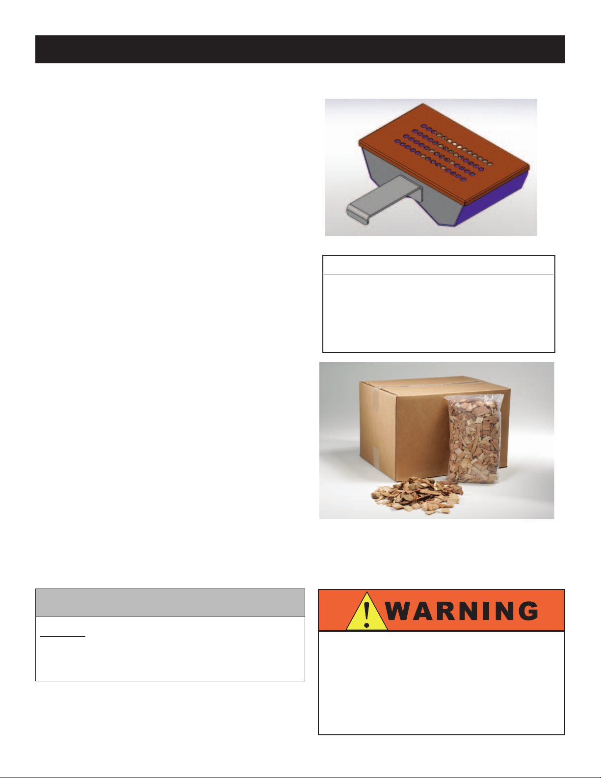
LOAD WOOD CHIPS.
• Measure one container full of dry wood chips.
• Soak dry chips in water for 5 minutes.
• Shake excess water off wood chips.
• Place moistened chips back into the container
and position the container securely on the two prongs
located on the interior back panel of the oven.
A full container of wood chips will produce smoke for an
approximate period of one to two hours depending on the
cooking temperature being used for the selected product.
The preprogrammed CombiTouch recipes have been
tested to ensure complete product smoke penetration and
full smoke avor.
CHEF OPERATING TIP
Products such as ribs that require heavier smoke
penetration to reach full smoke avor should remain in
the oven after cooking has been completed. Do not open
the oven door.
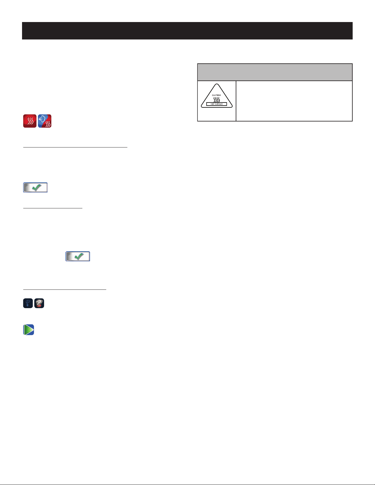
AVAILABLE FROM ALTO-SHAAM
WOOD CHIPS 20 pound bulk packs
THE TOTAL WEIGHT OF
Apple WC-22543
WOOD CHIP BULK PACKS
Hickory WC-2829
MAY VARY DUE TO HIGH
MOISTURE CONTENT
Cherry WC-22541
WHEN PACKAGED.
Sugar Maple WC-22545
Set the oven in the Low Temperature Steam Mode at 140°
to 160°F (60° to 71°C) and allow the product to remain in
the oven for a period of one hour.
If you would like assistance, you are invited to contact
an Alto-Shaam corporate chef for recommendations.
NOTE: Always keep the oven door closed whenever
operating the smoking function.
The CombiTouch CombiSmoker can be operated
without using the smoking function. After using the
oven as a smoker, however, it is necessary to clean the
oven in order to prevent a transfer of smoke avor to
non-smoked products. Cleaning instructions are provided
in this manual.
CAUTION
DO NOT OPEN THE OVEN DOOR DURING THE
SMOKING FUNCTION. The introduction of outside
air in the oven compartment may cause the wood
chips to flame.
THE USE OF IMPROPER MATERIALS FOR
THE SMOKING FUNCTION COULD RESULT IN
DAMAGE, HAZARD, EQUIPMENT FAILURE,
OR COULD REDUCE THE OVERALL LIFE
OF THE OVEN.
20
DO NOT USE SAWDUST FOR SMOKING.
DO NOT USE WOOD CHIPS SMALLER
THAN THUMBNAIL SIZE.
Page 24
OPERATING INSTRUCTIONS
CombiSmoker™ ProCedureS
The ability to smoke product, hot or cold, is offered on
all boiler-free electric models and on all gas models.
The smoking function can be engaged in either the
Combination mode or the Convection mode of operation.
The smoking function cannot be operated when the oven
is operating in the steam mode or the retherm mode.
SELECT CONVECTION OR COMBINATION
COOKING MODE.
TO CHANGE THE TEMPERATURE:
TOUCH THE DISPLAYED TEMPERATURE.
Type desired temperature or use up and down arrows to
adjust temperature then touch the green checkmark key
to conrm.
TO COOK BY TIME:
CAUTION
METAL PARTS OF THIS EQUIPMENT
BECOME EXTREMELY HOT WHEN
IN OPERATION. TO AVOID BURNS,
ALWAYS USE HAND PROTECTION
WHEN OPERATING THIS APPLIANCE.
TOUCH THE DISPLAYED TIME.
The cooking time will appear at the top the time selection
window. Type in desired time period or use up and down
arrows to adjust time. When nished, touch the green
checkmark key to conrm change.
Or, to set Continuous Operation mode, type in --:-- and
touch the green checkmark key to conrm.
TO ACTIVATE CombiSmoke:
Press the SMOKING icon. The icon will be
highlighted on the screen.
PRESS THE GREEN START ARROW ICON TO
BEGIN COOKING.
21
Page 25
OPERATING INSTRUCTIONS
PREPROGRAMMED RECIPES
The CombiTouch Combitherm comes preprogrammed
with more than 100 recipes and photo icons, covering
most commonly prepared food items. CombiTouch
also allows you to save up to 250 of your recipes and
uploaded photos.
MAIN MENU COOKING MODE MENU
Select RECIPE MODE from any screen.
Navigate to desired recipe icon using green NEXT and
PREVIOUS SCREEN arrows. Press icon for desired recipe.
Cooking steps will start immediately. (See 24-33 for a list
of all preprogrammed recipes.)
PROGRAMMED
RECIPES
NUMBER OF
RECIPE SCREENS
PREVIOUS
SCREEN
RECIPE MENU
EDIT
RECIPES
PREVIOUS &
NEXT SCREEN
RECIPE
MODE
& NEXT RECIPE
PROGRAM/EDIT RECIPES
EDITABLE
RECIPES
PREVIOUS
DELETE
RECIPE
EDIT
RECIPE
CONFIRM
CHANGES
22
Page 26

OPERATING INSTRUCTIONS
RECIPE PROGRAMMING VIA RECIPE MANAGEMENT SOFTWARE
The recipes can be edited, using the Touchscreen directly
or with the Recipe Management Software. This Windows
based software and step-by-step instructions are available
for download via the Alto-Shaam website.
http://www.alto-shaam.com/combitouch.aspx
RECIPE PROGRAMMING VIA THE TOUCHSCREEN
ADD A RECIPE
The recipe programming function allows the operator
to program a cooking procedure using multiple cooking
modes and any auxiliary functions desired. Recipes
remain programmed until deleted by the operator.
1. Select any cooking mode.
2. Click ADD RECIPE icon.
3. Select rst desired cooking mode. Last input
temperature, time and probe setting will be displayed.
4. Change temperature, time and/or cook by probe as
desired.
5. Change auxilary functions as desired (fan speed,
Gold-N-Brown, etc.)
6. When nished with cooking step, press WRITE
icon. Will display next cooking step programming
screen.
7. Repeat steps 3 through 6 for each cooking step or
proceed to step 8 if only one step in recipe.
8. When nished programming recipe, touch the
CONFIRM CHANGES icon.
9. A keypad will appear. Input name of recipe and assign
a picture. Touch the picture icon to display the picture
instead of text on recipe menu. Press CONFIRM
CHANGES icon.
®
DOWNLOAD
LINK
EDIT A RECIPE
To edit an existing default or user-programmed recipe:
1. Select RECIPE SETTINGS MODE from the Recipe
Menu. The touch screen background will turn red to
indicate that the user is in EDIT MODE.
2. Press the icon of the recipe to be edited. Selected recipe
will be highlighted.
3. Press EDIT RECIPE. The rst cooking step in the
recipe will be displayed.
Or click DELETE RECIPE to remove recipe.
Click CONFIRM CHANGES to conrm deletion.
4. Edit cooking mode, temperature, time, probe
temperature and/or auxilary functions.
5. Press CONFIRM CHANGES. A keyboard will
appear. Edit the title as appropriate. Select a picture
if desired, by pushing the picture icon to view the
picture library.
Press CONFIRM CHANGES at the bottom of
the keyboard.
6. Press CONFIRM CHANGES at the bottom of the
touch screen to exit EDIT RECIPE mode.
10. The saved recipe will appear as the rst recipe in
the list.
11. Touch the newly saved recipe icon. Cooking steps in
recipe will immediately start.
23
Page 27
OPERATING INSTRUCTIONS
PREPROGRAMMED BAKERY RECIPES
Icon Recipe Oven Mode Temp Time
Fan
Speed Smoker Browning
Bakery retherm Retherm
Brownies Convection
Cinnamon Rolls Combination
Cookies Convection
Croissants Combination
Danish Pastry Combination
Dinner Rolls Combination
French Bread Combination
275°F
(135°C)
325°F
(163°C)
350°F
(177°C)
325°F
(163°C)
325°F
(163°C)
350°F
(177°C)
350°F
(177°C)
350°F
(177°C)
4 minutes 100% -- --
25 minutes 100% -- --
20 minutes 100% -- --
12 minutes 50% -- --
15 minutes 50% -- --
15 minutes 100% -- --
10 minutes 100% -- --
20 minutes 100% -- --
Fruit Bread Combination
Fruit Pie Combination
Muffins Convection
Par-baked Bread (frozen) Combination
Par-baked Rolls Combination
Proofing Low Temp Steam
Puff Pastry Combination
Sheet Cake Convection
300°F
(149°C)
340°F
(171°C)
325°F
(163°C)
340°F
(171 °C)
350°F
(177°C)
90°F
(32°C)
350°F
(177°C)
325°F
(163°C)
50 minutes 100% -- --
30 minutes 100% -- --
15 minutes 50% -- --
15 minutes 100% -- --
10 minutes 100% -- --
30 minutes 50% -- --
10 minutes 100% -- --
20 minutes 50% -- --
24
Page 28
OPERATING INSTRUCTIONS
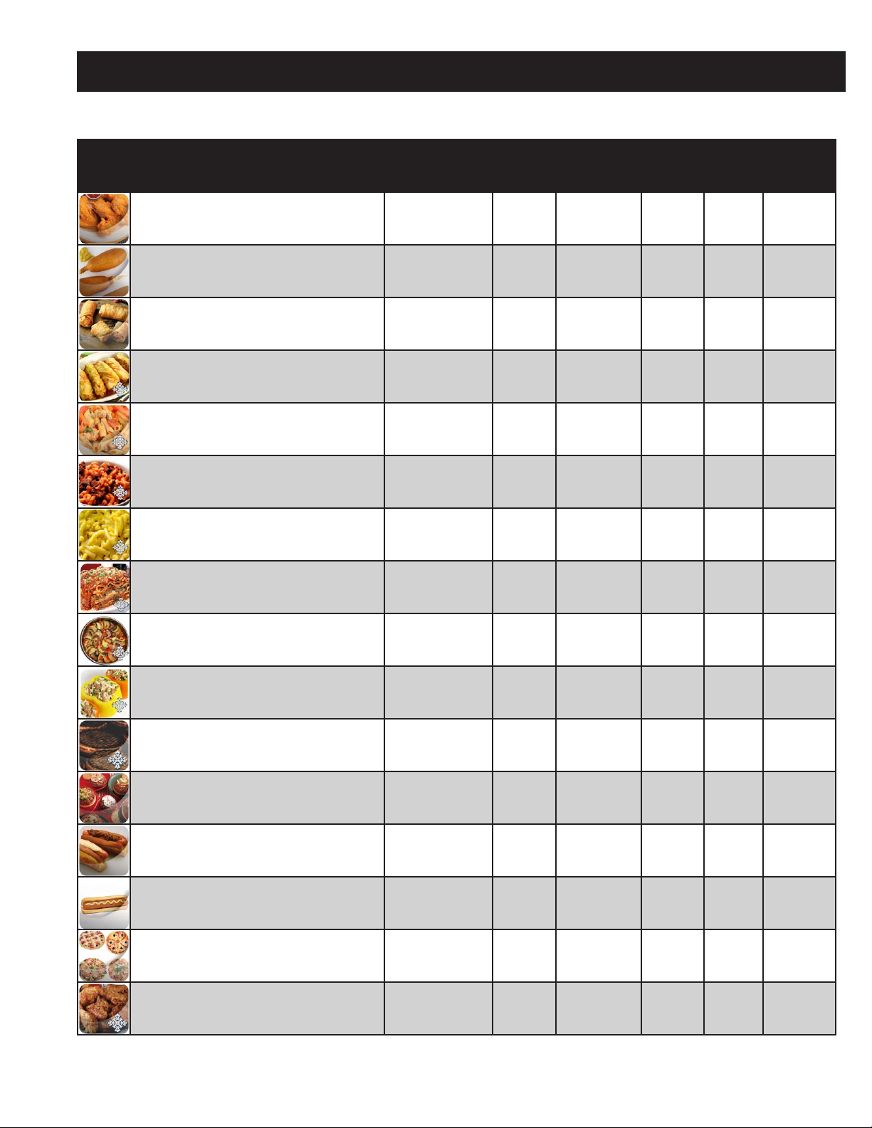
PREPROGRAMMED CONVENIENCE PRODUCT RECIPES
Icon Recipe Oven Mode Temp Time
Chicken Wings Combination
Corn Dogs Combination
Egg Rolls Combination
Frozen Entrée: Cabbage Rolls
Frozen Entrée: Chicken Primavera
Frozen Entrée: Macaroni & Beef
Frozen Entrée: Macaroni & Cheese
Frozen Entrée: Meat Lasagna
Combination
Combination
Combination
Combination
Combination
400°F
(204°C)
350°F
(177°C)
375°F
(191°C)
350°F
(177°C)
350°F
(177°C)
350°F
(177°C)
350°F
(177°C)
350°F
(177°C)
10 minutes 100% -- 2
18 minutes 100% -- 1
15 minutes 100% -- 3
160°F probe
(71°C)
160 minutes 100% -- --
145 minutes 100% -- --
140 minutes 100% -- --
150 minutes 100% -- --
Fan
Speed Smoker
100% -- --
Browning
Level
Frozen Entrée: Ratatouille
Frozen Entrée: Stuffed Peppers
Hamburger Patties - Frozen Combination
Hamburger Patties - Thawed Combination
Hot Dogs - Low Temp Steam Low Temp Steam
Hot Dogs - Steamed Steam
Mini Pizza Combination
Precooked Chicken Pieces - Frozen (MRB) Convection
Combination
Combination
350°F
(177°C)
350°F
(177°C)
350°F
(177°C)
350°F
(177°C)
160°F
(71°C)
212°F
(100°C)
350°F
(177°C)
365°F
(185°C)
35 minutes 100% -- --
150 minutes 100% -- --
12 minutes 100% -- 4
5 minutes 100% -- --
13 minutes 50% -- --
10 minutes 100% -- --
10 minutes 100% -- --
30 minutes 100% -- 3
25
(CONTINUED ON NEXT PAGE)
Page 29

OPERATING INSTRUCTIONS
PREPROGRAMMED CONVENIENCE PRODUCT RECIPES (CONTINUED)
Icon Recipe Oven Mode Temp Time
Precooked Chicken Pieces - Refrigerated Convection
Spring Rolls Combination
Tater Tots Combination
325°F
(163°C)
375°F
(191°C)
375°F
(191°C)
20 minutes 100% -- 1
15 minutes 100% -- --
10 minutes 100% -- 3
Fan
Speed Smoker
Browning
Level
26
Page 30
OPERATING INSTRUCTIONS
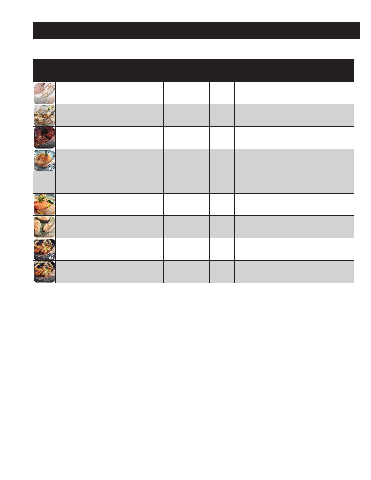
PREPROGRAMMED FISH & SEAFOOD RECIPES
Icon Recipe Oven Mode Temp Time
Baked Fish - Fresh Combination
Grilled Fish Fillets Combination
Lobster - Whole Steam
Salmon - Cold Smoked (1) Convection
(2) Convection
Salmon - Filets Low Steam
Salmon - Steaks Steam
Shrimp - Smoked Convection
400°F
(204°C)
460°F
(238°C)
195°F
(91°C)
34°F
(1°C)
34°F
(1°C)
145°F
(63°C)
145°F
(63°C)
34°F
(1°C)
6 minutes 100% -- 2
4 minutes 100% -- --
13 minutes 50% -- --
15 minutes 50% On --
30 minutes 50% Off --
7 minutes 50% -- --
8 minutes 100% -- --
10 minutes 50% On --
Fan
Speed Smoker
Browning
Level
Shrimp - Steamed Low Steam
160°F
(71°C)
12 minutes 50% -- --
27
Page 31

OPERATING INSTRUCTIONS
PREPROGRAMMED MEAT RECIPES
Icon Recipe Oven Mode Temp Time
Bacon Combination
Beef Brisket - Smoked (1) Combination
(2) Combination
Beef Roast Cook & Hold (1) Delta-T
(2) Steam
Beef Rounds - by Core Temp Delta-T
Beef Rounds - by Time Combination
Beef Short Ribs Combination
375°F
(191°C)
225°F
(107°C)
225°F
(107°C)
125°F
(52°C)
135°F
(57°C)
130°F
(54°C)
250°F
(121°C)
275°F
(135°C)
10 minutes 100% -- --
90 minutes 50% On --
180 minutes 50% -- --
Probe 120°F
(46°C)
Continuous 50% -- 2
Probe 125°F
(52°C)
130 minutes 100% -- --
90 minutes 100% -- --
Fan
Speed Smoker
50% -- --
100% -- 1
Browning
Level
Beef Short Ribs - Smoked (1) Combination
(2) Combination
Beef Tenderloin Combination
Beef Tri-tips Combination
Breakfast Sausage Links Combination
Grilled Pork Chops Combination
Grilled Steaks Combination
275°F
(135°C)
275°F
(135°C)
250°F
(121°C)
250°F
(121°C)
350°F
(177°C)
460°F
(238°C)
460°F
(238°C)
30 minutes 50% On --
60 minutes 100% -- --
Probe 125°F
(52°C)
Probe 125°F
(52°C)
8 minutes 100% -- --
6 minutes 100% -- 1
Probe 130°F
(54°C)
100% -- 2
100% -- 3
100% -- --
(CONTINUED ON NEXT PAGE)
28
Page 32

OPERATING INSTRUCTIONS
PREPROGRAMMED MEAT RECIPES (CONTINUED)
Icon Recipe Oven Mode Temp Time
Ham - by Core Temp Delta-T
Leg of Lamb - by Core Temp Delta-T
Meat Loaf - by Core Temp Combination
Pork - Back Ribs - Raw Combination
Pork - Back Ribs - Smoked (1) Combination
(2) Steam
Pork - Loin Roast - by Core Temp Combination
Pork Ribs Reheat Combination
125°F
(52°C)
125°F
(52°C)
275°F
(135°C)
250°F
(121°C)
250°F
(121°C)
160°F
(71°C)
300°F
(149°C)
400°F
(204°C)
Probe 150°F
(66°C)
Probe 130°F
(54°C)
Probe 155°F
(68°C)
45 minutes 100% -- --
60 minutes 100% On --
Continuous 50% -- --
Probe 150°F
(66°C)
7 minutes 100% -- --
Fan
Speed Smoker
50% -- --
100% -- 2
100% -- 3
100% -- 2
Browning
Level
Pork Shoulder - Smoked (1) Combination
(2) Combination
Rack of Lamb - by Core Temp Delta-T
Sausage - Fresh - by Low Temp Steam Low Temp Steam
225°F
(107°C)
225°F
(107°C)
130°F
(54°C)
160°F
(71°C)
90 minutes 100% On --
Probe 185°F
(85°C)
130 minutes 100% -- 2
15 minutes 50% -- --
-- --
29
Page 33

OPERATING INSTRUCTIONS
PREPROGRAMMED MISCELLANEOUS RECIPES
Icon Recipe Oven Mode Temp Time
Casseroles - by Core Temp Combination
Casseroles - Time Combination
Custard/Crème Brulee
Eggs - Hardboiled Steam
Eggs - Poached - Low Temp Steam Low Temp Steam
Eggs - Poached - Steamed Steam
Eggs - Scrambled in bag; shake at
18 minutes
Eggs - Scrambled in pan Steam
Low Temp Steam
Steam
350°F
(177°C)
350°F
(177°C)
190°F
(88°C)
212°F
(100°C)
170°F
(77°C)
212°F
(100°C)
212°F
(100°C)
212°F
(100°C)
Probe 150°F
(66°C)
30 minutes 100% -- --
45 minutes 50% -- 1
12 minutes 100% -- --
5 minutes 50% -- --
3 minutes 100% -- --
25 minutes 100% -- --
15 minutes 100% -- --
Fan
Speed Smoker
100% -- --
Browning
Level
Eggs - Sous Vide Steam
French Fries - Full Load (1) Convection
(2) Combination
Pasta Steam
Pate en Croute - by Core Temp (1) Convection
(2) Combination
Pizza - Fresh Combination
Rice Steam
Soup in Bag Steam
148°F
(64°C)
400°F
(204°C)
400°F
(204°C)
212°F
(100°C)
350°F
(177°C)
350°F
(177°C)
400°F
(204°C)
212°F
(100°C)
230°F
(110°C)
45 minutes 50% -- --
1 minute 100% -- 4
9 minutes 100% -- 2
20 minutes 100% -- --
10 minutes 100% -- --
Probe 135°F
(57°C)
10 minutes 50% -- 1
20 minutes 100% -- --
50 minutes 100% -- --
100% -- --
Tamales Steam
30
212°F
(100°C)
30 minutes 100% -- --
Page 34

OPERATING INSTRUCTIONS
PREPROGRAMMED POULTRY RECIPES
Icon Recipe Oven Mode Temp Time
Chicken - Frozen Pieces Combination
Chicken - Oven Fried Pieces Combination
Chicken - Thawed Whole Combination
Chicken - Thawed Whole - by Core Temp Combination
Chicken - Whole Smoked (1) Convection
(2) Combination
Chicken baked - Thawed Pieces Combination
Duck Pieces - Raw Combination
350°F
(177°C)
450°F
(232°C)
350°F
(177°C)
350°F
(177°C)
34°F
(1°C)
350°F
(177°C)
375°F
(191°C)
375°F
(191°C)
30 minutes 100% -- 3
18 minutes 100% -- --
35 minutes 100% -- 1
Probe 175°F
(79°C)
15 minutes 50% On --
Probe 175°F
(79°C)
Probe 170°F
(77°C)
25 minutes 100% -- 4
Fan
Speed
100% -- 1
50% -- --
100% -- 2
Smoker
Browning
Level
Duck Whole - by Core Temp (1) Combination
(2) Combination
(3) Combination
Galantine - by Core Temp Low Temp Steam
Grilled Chicken Breasts Combination
Turkey Breast - Precooked - by Time Combination
Turkey Breast - Raw - by Core Temp Combination
Turkey Breast - Smoked (1) Combination
250°F
(121°C)
300°F
(149°C)
400°F
(204°C)
160°F
(71°C)
460°F
(238°C)
275°F
(135°C)
275°F
(135°C)
275°F
(135°C)
15 minutes 100% -- --
10 minutes 100% -- --
Probe 175°F
(79°C)
Probe 135°F
(79°C)
6 minutes 100% -- --
Probe 155°F
(68°C)
Probe 155°F
(68°C)
60 minutes 50% On --
100% -- 3
50% -- --
50% -- --
50% -- 1
(2) Combination
31
275°F
(135°C)
Probe 155°F
(68°C)
100% -- --
Page 35

OPERATING INSTRUCTIONS
PREPROGRAMMED VEGETABLE RECIPES
Icon Recipe Oven Mode Temp Time
Asparagus - Fresh Steam
Asparagus - Frozen Steam
Baked Potatoes Combination
Beets - Fresh Steam
Broccoli - Fresh Steam
Broccoli - Frozen Steam
Brussel Sprouts - Frozen Steam
Cabbage - Fresh Steam
190°F
(88°C)
212°F
(100°C)
350°F
(177°C)
230°F
(110°C)
212°F
(100°C)
212°F
(100°C)
212°F
(100°C)
212°F
(100°C)
3 minutes 50% -- --
5 minutes 100% -- --
40 minutes 100% -- 1
20 minutes 100% -- --
6 minutes 100% -- --
3 minutes 100% -- --
6 minutes 100% -- --
10 minutes 100% -- --
Fan
Speed Smoker
Browning
Level
Carrots - Fresh Steam
Carrots - Frozen Steam
Cauliflower - Fresh Steam
Cauliflower - Frozen Steam
Corn (Kernels) - Frozen Steam
Corn-on-the-Cob - Fresh Steam
Corn-on-the-Cob - Frozen Steam
225°F
(107°C)
212°F
(100°C)
212°F
(100°C)
212°F
(100°C)
212°F
(100°C)
212°F
(100°C)
212°F
(100°C)
10 minutes 100% -- --
6 minutes 100% -- --
5 minutes 100% -- --
4 minutes 100% -- --
4 minutes 100% -- --
14 minutes 100% -- --
10 minutes 100% -- --
(CONTINUED ON NEXT PAGE)
32
Page 36

OPERATING INSTRUCTIONS
PREPROGRAMMED VEGETABLE RECIPES (CONTINUED)
Icon Recipe Oven Mode Temp
Green Beans - Fresh Steam
Green Beans - Frozen Steam
Parsnips - Fresh Steam
Peas - Frozen Steam
Potatoes, Red or Salad Steam
Squash - Fresh Steam
Turnips - Fresh Steam
Zucchini - Fresh Steam
212°F
(100°C)
212°F
(100°C)
230°F
(110°C)
212°F
(100°C)
212°F
(100°C)
212°F
(100°C)
230°F
(110°C)
212°F
(100°C)
Fan
Time
8 minutes
5 minutes
10 minutes
4 minutes
30 minutes
3 minutes
10 minutes
3 minutes 100% -- --
Speed Smoker
100% -- --
100% -- --
100% -- --
100% -- --
100% -- --
100% -- --
100% -- --
Browning
Level
33
Page 37

OPERATING INSTRUCTIONS
HACCP ACCESS
The CombiTouch Combitherm meets the requirements
of established HACCP criteria by providing automated
sampling, record keeping, set-point validation, recipe
used, dates and time. Data is captured when Core
Temperature Probe cooking method is chosen. This data
is retained for the last 30 days. This information can be
viewed on screen or downloaded to a USB drive and then
copied to your computer. The le format is a text (.txt)
le.
NOTE: You access this information from the
Settings Screen. See illustrations on page 2 and 3
for navigation.
1. To download the data collected, remove the cap of a
USB port located on the left side of the oven and insert
the USB ash drive. If the ash drive is not recognized
by the Combitherm, a question mark will appear on
screen. Try again with another ash drive device or
call Alto-Shaam Service.
2.
3.
4. PRESS TO CONFIRM TRANSFER.
5. Remove the USB ash drive and replace the cap on the
USB port located on the left side of the oven.
The download process will automatically create a folder
on the USB ash drive titled “haccp”. Each text le
contains cooking program specics. See illustration below.
PRESS TO DOWNLOAD INFORMATION.
WAIT FOR THE ICON TO CHANGE FROM
LOADING TO COMPLETE.
COOKING
PROGRAM
CHOSEN
DATE
COOKED
TIME
OF DAY
COOKED
PREVIOUS
SCREEN
CORE
TEMPERATURE
RECIPE
USED
HACCP
DOWNLOAD
34
Page 38

CLEANING & MAINTENANCE
The CombiTouch Combitherm offers four (4) cleaning
levels: rinse, light, normal, and heavy-duty cleaning.
CombiClean tablets or Combitherm spray cleaner may be
used. Side racks, shelves and trolleys may remain inside
oven during cleaning.
SELECT CLEANING MODE FROM ANY SCREEN.
NOTE: If oven is too hot to safely clean, an oven with red
interior will appear on the screen and the cool
down function is automatically activated. Allow
oven to cool to 200°F before cleaning.
SELECT RINSE, LIGHT,
NORMAL, OR HEAVY-DUTY CLEANING.
INSERT APPROPRIATE NUMBER OF CombiClean
TABLETS as directed by touchscreen or spray interior of
oven with combi cleaner. User may add one additional
tablet in either normal or heavy duty modes for
particularly dirty ovens.
PRESS THE GREEN START ARROW ICON TO
BEGIN CLEANING.
PRESS GREEN WATER ON ICON TO CONFIRM
THAT WATER SUPPLY IS TURNED ON.
CLEANING MODE MENU
WATER ON
RINSE
LIGHT
CLEANING
CYCLE
PREVIOUS
SCREEN
Leave door slightly ajar when cleaning is nished.
See CLEANING MODE MENU illustration below for
additional cleaning mode information.
COMBI CLEANER REQUIREMENT
The number of required CombiClean
tabs is shown via an animation
WATER OFF
HEAVY-DUTY
CLEANING CYCLE
NORMAL
CLEANING
CYCLE
START/STOP
CLEANING IN PROCESS
OVEN TOO HOT WARNING
Must allow oven to cool down before inserting
CombiClean tabs or spraying with cleaner
35
Page 39

CLEANING & MAINTENANCE
PREVENTATIVE MAINTENANCE
In addition to the routine cleaning and maintenance
procedures, there are several additional steps to be
taken for both sanitation and to keep the oven running
efciently. These additional safeguards will help prevent
down time and costly repairs.
DO NOT DISPOSE OF GREASE, FAT, OR SOLID
WASTE DOWN THE OVEN DRAIN.
Fats and solids will eventually coagulate in the drain
system, causing blockage. Consequently, water
will back-up into the condenser and interior oven
compartment, resulting in an oven that is inoperable.
MAKE CERTAIN THE DRAIN SCREEN IS ALWAYS
IN PLACE. REMOVE ANY SOLID WASTE MATERIAL
FROM THE DRAIN SCREEN BEFORE IT ENTERS THE
DRAIN SYSTEM.
The routine removal of solids from the drain screen will
help prevent blockage.
USE THE AUTHORIZED COMBITHERM OVEN
CLEANER ONLY.
The use of unauthorized cleaning agents may discolor or
harm the interior surfaces of the oven.
TO PROLONG THE LIFE OF THE DOOR GASKET,
CLEAN THIS ITEM DAILY.
The acids and related compounds found in fat,
particularly chicken fat, will weaken the composition of
the gasket unless cleaned on a daily basis. Wipe with a
hot, soapy cloth.
TO ADDITIONALLY PROTECT GASKET LIFE,
ALLOW OVEN DOOR TO REMAIN SLIGHTLY OPEN
AT THE END OF THE PRODUCTION DAY.
An open door will relieve the pressure on the door gasket.
ROUTINELY CLEAN DOOR HINGES.
Open oven door to relieve tension. Clean all parts of
the hinge.
CLEAN PRONGS OF
REMOVABLE PROBE DAILY.
To ensure accurate internal
product temperature readings,
the prongs on the removable
probe must be cleaned daily.
ROLL-IN CART/FOOD TROLLEY CLEANING (ON EQUIPPED MODELS)
1. Remove food trolley to a cart wash area. Trolleys may be cleaned using
any mild cleaning detergent and warm water.
2. Hand wipe all framing, slides, drip pan, and base. Thoroughly clean
debris from the casters. A spray hose can be used for easier cart cleaning.
3. Remove detergent solution with warm water.
4. Wipe or spray with a sanitizing solution designed for use on metal and
vinyl food contact surfaces.
5. Allow trolley to air dry.
As an alternative, trolleys can be cleaned while inside the oven. Allow the
trolley to remain in the oven through the normal cleaning cycle, followed by
steps 2 through 5 above.
36
Page 40

CLEANING & MAINTENANCE
The cleaning function can usually be accomplished
scratches. Never use wire brushes, metal scouring
CLEANING AND PREVENTIVE MAINTENANCE
PROTECTING STAINLESS STEEL SURFACES
It is important to guard against corrosion
in the care of stainless steel
surfaces. Harsh, corrosive,
or inappropriate chemicals
can completely destroy the
protective surface layer
of stainless steel. Abrasive
pads, steel wool, or metal implements will abrade
surfaces causing damage to this protective coating
and will eventually result in areas of corrosion.
Even water, particularly hard water that contains
high to moderate concentrations of chloride, will
cause oxidation and pitting that result in rust
and corrosion. In addition, many acidic foods
spilled and left to remain on metal surfaces are
contributing factors that will corrode surfaces.
Proper cleaning agents, materials, and
methods are vital to maintaining the appearance
and life of this appliance. Spilled foods should be
removed and the area wiped as soon as possible
but at the very least, a minimum of once a day.
Always thoroughly rinse surfaces after using a
cleaning agent and wipe standing water as quickly
CLEANING AGENTS
Use non-abrasive cleaning products designed for
use on stainless steel surfaces. Cleaning agents
must be chloride-free compounds and must not
contain quaternary salts. Never use hydrochloric
acid (muriatic acid) on stainless steel surfaces.
Always use the proper cleaning agent at the
manufacturer's recommended strength.
Contact your local cleaning supplier for
product recommendations.
CLEANING MATERIALS
with the proper cleaning agent and a soft, clean
cloth. When more aggressive methods must be
employed, use a non-abrasive scouring pad on
difficult areas and make certain to scrub with the
visible grain of surface metal to avoid surface
pads, or scrapers to remove food residue.
CAUTION
A
R
P
C
E
S
O
N
W
O
N
S
O
N
R
TO PROTECT STAINLESS STEEL
S
SURFACES, COMPLETELY AVOID
THE USE OF ABRASIVE CLEANING
B
E
R
I
COMPOUNDS, CHLORIDE BASED
R
U
S
H
CLEANERS, OR CLEANERS
E
S
CONTAINING QUATERNARY SALTS.
NEVER USE HYDROCHLORIC ACID
E
L
E
T
(MURIATIC ACID) ON STAINLESS
P
A
D
S
STEEL. NEVER USE WIRE
BRUSHES, METAL SCOURING
PADS OR SCRAPERS.
37
Page 41

CLEANING & MAINTENANCE
CLEANING SCHEDULE
DAILY GASKET CLEANING
It is important to prolong the life of the oven gasket by
cleaning on a daily basis. Routine cleaning will help
protect the gasket from deterioration caused by acidic
foods.
1. Allow the oven to cool, then wipe the gasket and
crevices with clean cloth soaked in warm detergent
solution.
2. Wipe the gasket and crevices with a cloth and clean
rinse water.
Do not attempt to remove gasket or place in the
dishwasher.
PROBE USAGE AND CLEANING
After each use of the CORE TEMP mode, wipe the probe
tip with a clean paper towel to remove food debris. Follow
by wiping the probe with a disposable alcohol pad. Return
the probe to the proper door bracket position.
Probe Cleaning Procedures
1. Remove all food debris from probe between loads and
at the end of each production shift. Wipe the entire
probe, probe cable assembly, and probe holding bracket
with a clean cloth and warm detergent solution.
DAILY STEAM GENERATOR FLUSH
(Electric boiler equipped models only)
See next page for instructions
The steam generator must be ushed once a day when
operating the oven on a regular basis. This procedure will
prevent lime deposits and scale build-up from forming
in the steam generator. A steam generator ush is
automatically initiated during the cleaning function.
DAILY PRONG CLEANING
To ensure accurate internal
product temperature readings,
the prongs on the removable
probe must be cleaned daily.
1. Remove all food debris from
prongs at the end of each
production shift. Wipe the
entire prong casing, and between each prong with a
clean cloth and warm detergent solution.
2. Remove detergent by wiping with a cloth and clean
rinse water.
3. Allow to air dry before replacing detachable probe.
2. Remove detergent by wiping the probe, cable, and
bracket with a cloth and clean rinse water.
3. Wipe probe and probe bracket with disposable alcohol
pad or sanitizing solution recommended for food
contact surfaces.
4. Allow probe and cable to air dry in the probe
holding bracket.
5. Wipe the probe with a disposable alcohol pad prior to
inserting into a new food product.
DAILY OVEN CLEANING
To be performed at the end of the production day or
between production shifts.
REGULAR DECALCIFICATION
(Electric boiler equipped models only)
Qualified service technician should see CombiTouch Technical
Manual for instructions
It is important to decalcify the steam generator,
particularly in areas with extremely hard water. In
addition to the daily steam generator ush, this procedure
should be performed once a month by a qualied service
technician or more frequently depending on usage and
water conditions.
MONTHLY CLEANING
1. Spray Head
2. Water Intake Filter
3. Drain Pipe
2
3
1
38
Page 42

CLEANING & MAINTENANCE
Com biClea n CLEANING AGENTS
DANGER
RUBBER GLOVES MUST BE WORN WHEN USING
COMBICLEAN TABLETS OR SPRAY OVEN CLEANER.
NOTE: Use authorized Combitherm cleaner only.
Unauthorized cleaning agents may discolor or harm
interior surfaces of the oven. Read and understand
label and material safety data sheet before using the
oven cleaner.
CAUTION: Causes eye, skin, and respiratory tract
irritation. keep out of reach of children.
PRECAUTIONS:
- Do not take internally.
- Avoid contact with eyes and skin.
- Use rubber gloves when using this product.
- Wash hands thoroughly after handling.
- Avoid mixing with strong, concentrated acids.
AUTOMATIC STEAM GENERATOR FLUSH
Flushing the electric Combitherm steam generator on a
daily basis helps prolong the life of the steam generator
heating elements and reduces the need for service. The
CombiTouch provides this feature as an automatic
function once every 24 hours.
The steam generator ush is automatically activated when
the oven is powered on if no cleaning program has run
during the last 24 hours. An indicator icon will notify the
FIRST AID:
Skin: Flush with water. Remove contaminated clothing
and do not re-wear until washed. If irritation persists see
a physician.
Eyes: Flush with water for 15 minutes. See a
physician immediately.
Inhalation: If difculty in breathing occurs, leave area
immediately and do not return until dust is settled. If
irritation persists, see a physician.
Ingestion: Drink large quantities of milk or water. DO
NOT INDUCE VOMITING. See a physician immediately.
PROTECTIVE PACKAGING OF TABLETS WILL
BEGIN TO DISSOLVE ONTO SKIN IF HANDLED
WITH DAMP OR WET HANDS.
user that ushing is in process. This function cannot be
manually turned on or off and users cannot start a cooking
sequence during the generator ush. Wait until the ush
cycle is nished, then begin to use the oven as normal.
If the operator cleans the oven daily, it will not
automatically ush as this is one of the functions of the
cleaning cycles.
DECALCIFICATION (ON BOILER EQUIPPED MODELS)
USING SCALEFREE™
DECALCIFICATION MUST BE PERFORMED BY A
QUALIFIED SERVICE TECHNICIAN. QUALIFIED
TECHNICIANS SHOULD REFER TO THE ALTOSHAAM COMBITOUCH TECHNICAL MANUAL FOR
DECALCIFICATION PROCEDURES.
ScaleFree™ Descaling Compound is an acid-based
descaler combined with a proprietary chelating agent
that is effective in dissolving and removing carbonate,
lime-scale and iron-scale build-up caused by hard water.
ScaleFree efciently and effectively removes lime-scale
build-up from combi ovens.
ScaleFree™ is a non-hazardous, Biodegradable Citrus
Based Powder that when mixed with water becomes a
powerful lime-scale remover.
DO NOT COOK IN ANY PROGRAM MODE
WITH SCALEFREE™ IN THE STEAM GENERATOR
SYSTEM.
39
Page 43

TROUBLESHOOTING
EMERGENCY OPERATION MODE
If the oven malfunctions, an error code will appear in the
display. In the event of an error, the Combitherm may be
operated on a limited basis. Error conditions under which
continued operation is possible are indicated by “Yes”
in the chart on the next page. To operate the oven in the
event of an error code:
PRESS THE START KEY TO ACKNOWLEDGE
THE ERROR.
The icons that begin to flash represent operational
modes that are still usable.
SELECT ONE OF THE AVAILABLE COOKING MODES
SET THE OVEN CONTROLS AS IF OPERATING UNDER
NORMAL CIRCUMSTANCES.
Depending on the error code involved, oven function,
such as temperature range, may be limited.
PRESS THE START ICON TO BEGIN THE
COOKING.
PRESS THE STOP KEY WHEN THE TIMER
EXPIRES.
The Combitherm will return to normal operation when
the oven fault is corrected.
40
Page 44

TROUBLESHOOTING
EMERGENCY OPERATION MODE (CONTINUED)
ERROR CODES
When the oven malfunctions, an error code will appear in the display.
PRESS THE START ICON TO ACKNOWLEDGE THE ERROR.
The icons that begin to flash represent operational modes that are still usable.
When the oven fault is corrected, the Combitherm will return to normal operation.
Error
Code
E01
E02
E03
E04
E11
E13
E15
E20
E21
E22
E23
E24
E25
E26
E27
E34
E36
E51
E53
E54
E55
E57
E93
E94
Model Mode
Display Shows
Low Water Boiler Yes No No No To 365°F No
Control Temp High Yes Yes No No No No
Fan Motor Error Yes Yes No No No No
Fan Motor 2 Error Yes Yes No No No No
Convection Temperature High Yes Yes BOILER UNITS
Boiler Temperature High Yes No No No Yes No
Condenser Temperature High Yes Yes No No To 356°F No
B11 Core Temperature Probe Single Point
Fault - HACCP only
N6 Cavity Probe Fault Yes Yes BOILER UNITS
B10 Core Temp Probe Fault Yes Yes BY TIME ONLY BY TIME ONLY BY TIME ONLY BY TIME ONLY
B4 Boiler Probe Fault Yes No No No No No
B5 Bypass Probe Fault Yes Yes No No Yes No
B3 Condenser Probe Fault Yes Yes Yes No To 356°F No
N8 Boiler Safety Temperature Probe Fault Yes No No No No No
Boiler Element Temperature High Yes No No No Yes No
Steam Generator Drain Pump Fault Yes No No No No No
Steam Temperature High Yes No No No Yes No
No Water in Boiler Yes No No No Yes No
Fan Motor High Temperature Yes Yes No No No No
Fan Motor 2 High Temperature Yes Yes No No No No
Vent Not Open Yes Yes Yes
No Rinse Water Yes Yes Yes Yes Yes Yes
Communication Error FROM Display Board Yes Yes No No No No
Communication Error TO Display Board Yes Yes No No No No
ES ESG
ESI
Yes Yes No No No No
Steam Combination Convection Retherm
No No No
ONLY
No No No
ONLY
NO BROWNING)
(
Yes
(NO BROWNING)
Yes
(NO BROWNING)
(NO BROWNING)
Yes
41
Page 45

TROUBLESHOOTING
CombiTouch ERROR CODES
This section is provided for the assistance of qualified technicians only and is not intended for use by
untrained or unauthorized service personnel. If your Alto-Shaam® unit is not operating properly, check the
following before calling your Authorized Alto-Shaam Service Agent:
☛ Check the power flow to the unit. Plug in outlet?
Do not attempt to repair or service the CombiOven beyond this point. Contact Alto-Shaam for the
nearest authorized service agent. Repairs made by any other service agents without prior authorization
by Alto-Shaam will void the warranty on the unit.
When the oven malfunctions, an error code will appear in the display.
PRESS THE START ICON TO ACKNOWLEDGE THE ERROR.
The icons that begin to flash represent operational modes that are still usable.
When the oven fault is corrected, the Combitherm will return to normal operation.
Error
Code
E01
E02
E03
E04
E11
Error Call Out in Display Description of Error Possible Cause
Low Water Boiler Low water level in boiler — Water supply is shut off.
Control Temperature High Relay board surface
temperature too high
Fan Motor Error Fan motor does not work — Exhaust hood is not operating properly.
Fan Motor 2 Error Lower fan motor on 20•20
does not work
Convection Temperature
High
Excess oven temperature Convection Mode & Combi Mode:
— Low water pressure.
— Generator drain cap missing or loose.
— Generator drain pump is not sealing.
— Generator drain pump elbow leaking.
— Faulty or scaled water level probe.
— Faulty or plugged dual solenoid valve assembly.
— Wiring or connection issue.
— No output to dual solenoid from relay board.
— Relay board, high voltage is not operating.
— Wiring or connection issue.
— Cooling fan on Relay board assembly is
not operating.
— Cooling Fan on display board is not operating.
— Main Cooling fan is not operating.
— Cooling Fan on motor drive is not operating.
— Unit is less than 20” from a heat producing source
on its left hand side.
— Check LED fl ashes on the Motor Control.
— See Motor Control Error Code list.
— Connection Issue on Hall Effect sensor.
— Fan whel is not operating.
— Hall sensor does not detect motor rotation.
— Exhaust hood is not operating properly.
— Check LED fl ashes on the Motor Control.
— See Motor Control Error Code list.
— Connection Issue on Hall Effect sensor.
— Fan wheel is not operating.
— Hall sensor does not detect motor rotation.
— Convection Oven contactor(s) stuck closed.
— N6 Oven Cavity Temperature probe defective.
— N6 Cavity Probe connection problem.
— Relay board, high voltage is not operating.
— Wiring or connection issue.
Combi Mode Only:
— Insuffi cient water supply into oven for
steam production.
(CONTINUED ON NEXT PAGE)
42
Page 46

CombiTouch ERROR CODES
TROUBLESHOOTING
Error
Code
E13
E15
E20
E21
E22
E23
E24
E25
E26
E27
Error Call Out in Display Description of Error Possible Cause
Boiler Temperature High Boiler temperature overheats — Scale build up inside steam generator.
Condensor Temperature High Excess condensor
temperature
HACCP Only - B11 Core
Temperature Probe Single
Point Fault
Error E20 is not shown in display.
Instead a probe sign with “?” is
shown as popup window. In case
the customer cooks in time mode
during fi rst step and during second
step switches to probe mode but has
no probe in place, the error E20 will
be shown in the error code list and
HACCP list.
N6 Cavity Probe Fault Cavity temperature probe
B10 Core Temperature Probe
Multipoint Fault
B4 Boiler Probe Fault Boiler temperature probe
B5 Bypass Probe Fault Bypass steam temperature
B3 Condensor Probe Fault Condensor water
N8 Boiler Safety
Temperature Probe Fault
Boiler Element Temperature
High
Single point core temperature
probe defect
or disconnected.
defect or disconnected
Multipoint core temperature
probe defect or disconnected
defect or disconnected
probe defect or disconnected
temperature probe defect or
disconnected
Steam generator heating
element protection probe
defect or disconnected
Excess steam generator
safety probe
— Scale build up on water level probe.
— B4 Probe connection problem.
— B4 probe faulty.
— Untreated water supply line is shut off.
— Untreated water supply line is connected to warm
water.
— B3 probe connection problem.
— B3 probe is faulty.
— Single solenoid valve Y2 obstructed or faulty.
— Wiring or connection problem.
— Relay board, high voltage is not operating.
— Clean Probe Receptacle Pins with sand paper.
— B11 Single Point Core Temperature probe with
quick connect, defective.
— B11 Single Point Core Temperature probe wires
with quick connect, disconnected.
— B11 Single Point Core Temperature probe
receptacle, defective.
— B11 Single Point Core Temperature probe
receptacle wires disconnected.
— N6 Oven Cavity Temperature probe defective.
— N6 Oven Cavity Temperature connection problem.
— B10 Multipoint Core Temperature probe defective.
— B10 Multipoint Core Temperature probe connection
problem.
— B4 Boiler temperature probe defective.
— B4 probe wires connection problem.
— B5 Bypass steam temperature probe defective.
— B5 Bypass steam temperature connection problem.
— B3 Condensor temperature probe defective.
— B3 Condensor probe connection problem.
— N8 Boiler temperature probe defective.
— N8 probe connection problem.
— Scale build up inside steam generator.
— Scale build up on water level probe.
— Water level probe connection failure.
— N8 boiler temperature probe defective.
— N8 probe connection problem.
— Steam element contactor(s) stuck closed.
— Wiring or connection problem.
43
(CONTINUED ON NEXT PAGE)
Page 47

TROUBLESHOOTING
CombiTouch ERROR CODES
Error
Code
E34
E36
E51
E53
E54
E55
Error Call Out in Display Description of Error Possible Cause
Steam Generator Drain
Pump Fault
Steam Temperature High Oven cavity temperature is
No Water In Boiler Water inside steam generator
Fan Motor High
Temperature
Fan Motor 2 High
Temperature
Vent not open Browning valve does not
Water level in steam
generator does not drop
during cleaning program
too high when operating in
a steam mode or cleaning
program
does not reach low water
level
Fan motor too hot — Exhaust hood is not operating properly.
20•20 lower fan motor too hot — Exhaust hood is not operating properly.
open
— Scale build up inside the steam generator drain
pump.
— Scale build up inside the steam generator affecting
water level probes.
— Generator drain pump is faulty
— Connection issue at drain pump.
— No output to pump from relay board.
— Water supply is shut off.
— Low water pressure.
— Wiring or connection issue.
— Water injection pipe obstructed.
— Water fl ow control valve plugged or defective.
— Dual solenoid valve Y-1 obstructed or defective.
— No output to solenoid valve form relay board.
— Water supply is shut off.
— Low water pressure.
— Generator drain cap missing or loose.
— Generator drain pump is not sealing.
— Generator drain pump elbow leaking.
— Faulty or scaled water level probe.
— Faulty or plugged dual solenoid valve assembly.
— Wiring or connection issue.
— No output to dual solenoid from relay board.
— Check LED fl ashes on the Motor Control.
— See Motor Control Error Code list.
— Connection Issue on Hall Effect sensor.
— Fan wheel is not operating.
— Hall sensor does not detect motor rotation.
— Check LED fl ashes on the Motor Control.
— See Motor Control Error Code list.
— Connection Issue on Hall Effect sensor.
— Fan wheel is not operating.
— Hall sensor does not detect motor rotation.
— Alignment issue between motor cam and vent
motor safety switch (micro switch).
— Fault vent valve (motor).
— Fault vent valve safety switch (micro switch).
— Wiring or connection problem.
44
(CONTINUED ON NEXT PAGE)
Page 48

CombiTouch ERROR CODES
TROUBLESHOOTING
Error
Code
E57
E93
E94
E98
E99
Error Call Out in Display Description of Error Possible Cause
No rinse water During rinse no water
fl ow is detected through
solenoid valve
Communication Error,
FROM Display Board
Communication Error,
TO Display Board
RB is in Cesius and DB is in
Fahrenheit
RB is in Fahrenheit and DB
is in Cesius
Communication error
between display board and
low voltage relay board
Communication error
between display board and
low voltage relay board
Confl ict of unit confi guration
in the setup menu
Confl ict of unit confi guration
in the setup menu
— Water supply is shut off.
— Low water pressure.
— Check wiring to all components mentioned below.
— Flow switch is dirty or defective.
— Dual water solenoid valve obstructed or faulty (Y3.)
— Relay board, high voltage, defective.
— Check ribbon cable connections mentioned below.
— Ribbon cable defective.
— Relay board, low voltage, connector defective.
— Display board connector defective.
— Check ribbon cable connections mentioned below.
— Ribbon cable defective.
— Relay board, low voltage, connector defective.
— Display board connector defective.
— Relay board and Data board do not match, use
setup menu to change format.
— Relay board and Data board do not match, use
setup menu to change format.
(SEE MOTOR CONTROL ERROR CHART ON NEXT PAGE)
45
Page 49

TROUBLESHOOTING
CombiTouch MOTOR CONTROL ERROR CODES
Type of Error Indication Release of Error
Undervoltage LED fl ashing sequence, with 1 fl ash per period. Voltage of intermediate circuit is less than 250V
Overvoltage LED fl ashing sequence, with 2 fl ashes per period. Voltage of intermediate circuit exceeds 445V
Excess
Temperature
Overcurrent LED fl ashing sequence, with 4 fl ashes per period.
Overcurrent LED fl ashing sequence, with 5 fl ashes per period. Intermediate circuit current exceeds 4.0A
Short-circuit LED fl ashing sequence, with 6 fl ashes per period.
Power on LED fl ashing sequence, with 7 fl ashes per period.
Watchdog LED fl ashing sequence, with 8 fl ashes per period. Watchdog of the microcontroller released, program crash
LED fl ashing sequence, with 3 fl ashes per period. Temperature sensor in the power unit is more than 93°C
Blocked motor, detected by current peak monitoring from
900 rpm rotating fi eld
Release of interrupt at intermediate circuit current larger
than 53A
Effective mains voltage does not correspond to jumper
setting 115V/230V
46
Page 50

Combitherm parts
Rear and Left-Hand Side Service Parts ................................................. 48
Plumbing Hoses .................................................................................. 52
CombiClean™ Inner Tube and Nozzle ................................................... 57
Condensation Tank ............................................................................. 57
Sprayer Holder Assembly ..................................................................... 58
Oven Light Assembly ........................................................................... 58
Smoker Box Assembly ......................................................................... 58
Hinge Assemblies ................................................................................ 59
Touch Control .................................................................................... 60
Routing of Ribbon Cable — Tabletop ................................................... 62
Routing of Ribbon Cable — Floor-Standing ........................................... 63
Combitherm Motor ............................................................................. 64
CombiClean™ Motor Pump Assembly ................................................... 65
Mechanical Parts –
Mechanical Parts –
Mechanical Parts –
Right-Hand Door Assembly –
Right-Hand Door Assembly –
Left-Hand Door Assembly –
Recessed Door Assembly –
Recessed Door Track –
Recessed Door Assembly –
Recessed Door Track –
Electrical Assemblies -
Electrical Assemblies -
6.10ESG, 10.10ESG, 7.14ESG ...................................... 66
12.18ESG, 10.20ESG ................................................. 67
20.20ESG ................................................................ 68
6.10ESG, 10.10ESG, 7.14ESG, 12.18ESG .......... 69
10.20ESG, 20.20ESG ......................................... 70
6.10ESG, 10.10ESG, 7.14ESG .............................. 71
6.10ESG, 10.10ESG, 7.14ESG, 12.18ESG .............. 72
6.10ESG, 10.10ESG, 7.14ESG ...................................... 73
10.20ESG, 20.20ESG ............................................. 74
12.18ESG, 10.20ESG, 20.20ESG .................................. 75
6.10ESG, 10.10ESG, 7.14ESG, 12.18ESG, 10.20ESG .... 76
20.20ESG ............................................................ 77
Return to Main Table of Contents ........................................................ 1
C o mb it he rm P a rt s • C O M B IT H E R M C OM B I T O UC H G A S T EC Hn I CA l SE R vI CE M An U Al • 47
Page 51

parts information
40 42
11
8
14
20
45
46
19
3
36
7
43
32
48
50
37
2
31
30
31
30
26
10
54
54
58
33
rear and Left-hand side serviCe parts — 6.10esG, 10.10esG,
7.14esG, 12.18esG,
16
22
52
8
24
1
15
5
9
29
28
50
48
36
39
53
11
10.20esG
51
49
35
25
51
21
34
47
49
18
6
54
7
36
3
2
10
19
4
19
37
50
48
32
43
8
11
26
54
17
25
30
31
55
56
27
57
30
31
46
30
31
C o mb it he rm P a rt s • C O M B IT H E R M C OM B I T O UC H G A S T EC Hn I CA l SE R vI CE M An U Al • 48
20
45
33
40 42
58
14
Page 52

Item Part Service Parts Description Qty.
1 1008395 Conical Washer 1
2 1008846 Bracket, Hose Guide 1
3 1010730 Bracket, Hose Guide 1
4 PB-28095 Condensor Tank 1
5 HO-27892 Hose, 7/8" 1
6 BG-29085 Bearing, Flanged Sleeve 2
7 BU-28391 Bushing, Socket Membrane 1
8 CM-29039 Clamp, Hose, 55mm 4
9 CM-29301 Clamp, Hose, 23mm 1
10 EB-22221 Elbow 1
11 EB-27207 Washer, Drain Support 2
12 FR-22496 Rubber “C” Gasket (not shown) 1.5’
13 FT-27406 Coupling, without Stop, 1.5" 1
14 FT-29124 Fitting, 1/2" Barb to 3/8" NPT Adaptor 1
15 FT-29263 Fitting 1
16 FT-29273 Fitting, Low Pressure 1
17 HO-27203 Hose, Hand Shower, 46" long 1
18 MO-34635 Pump, Circulation, 110V 1
MO-34636 Pump, Circulation, 208-240V 1
19 HO-2957 Hose, Steam Bypass 1
20 NP-27538 Valve Holder Assembly 2
21 NU-22292 Hex Nut 1
22 NU-22759 Hex Nut 1
23* NU-27107 Hex Nut Cap 1
24 NU-28710 Hex Jam Nut 1
25 PB-26960 Sprayer Holder 1
26 PB-27838 Plumbing, Nylon, 1/2" Y 1
27 PB-29162 Manifold, Injection Tube 1
28 PB-29289 Reducer Hose, 7/8" to 1/2" 1
29 PB-29489 Coupler, 1/2" to 1/2" 1
30 PR-33724 Thermocouple, Oven Temperature 1
parts information
*not shown
Item Part Service Parts Description Qty.
31 SA-25061 Thermocouple Probe 1
32 SA-26890 Seal, Vent Motor 1
33 SA-28149 O-Ring Seal 2
34 SC-22273 PH Pan Head Screw 2
35 SC-22766 Phillips Pan Head Screw 4
36 SC-22779 PH Pan Head Screw 5
37 SC-22926 Screw, M5 x 16 3
38* SL-3836 Sleeve, Grommet Edging 1.1’
39 TE-24257 1-3/4" OD Copper Tee 1
40 TE-27204 Tee Valve 1
41 TU-22256 Tubing, Black PVC, Wire Sleeve 5’
42 VA-25549 Valve, Flow Control, 13 gpm 1
43 VA-26838 Vent Motor with Switch 1
44* VA-29262 Low Pressure Valve 1
45 VA-34344 Valve, Single Port, 120V, Untreated 1
VA-34300 Valve, Single Port, 208-240V, Untreated 1
46 VA-34461 Valve, Double Port, 120V, Treated 1
VA-34045 Valve, Double Port, 208-240V, Treated 1
47 WS-22294 Washer, Flat 2
48 WS-22295 Washer, Flat 12
49 WS-22300 Washer, Split Lock 2
50 WS-22301 Washer, Split Lock 12
51 WS-24396 Washer, Serrated Bevel 1
52 WS-25092 Washer, Conical Seal 1
53 5004589 Vent Holder Assembly 1
54 FA-3599 Cooling Fan, 120V 2
FA-3568 Cooling Fan, 208V 2
55 SW-34399 Switch, Air Pressure 1
56 FA-34396 Combustion Blower Motor, 80W 1
57 VA-34398 Gas Valve 1
58 BA-34397 Ignition Module 1
C o mb it he rm P a rt s • C O M B IT H E R M C OM B I T O UC H G A S T EC Hn I CA l SE R vI CE M An U Al • 49
Page 53

parts information
rear & Left-hand side serviCe parts — 20.20esG
35
43
1
24
16
37
9
13
33
49
47
25
52
5123
49
47
15
30
41
42 5
27
13
179
12
9
37
13
53
18
2526
54
241
16
3
7
34
5
10
29
28
49
47
34
22
50
32
48
46
6
19
11
26
21
44 45
55
20
15
41
13 12
2
55
20
38
18
54
21
C o mb it he rm P a rt s • C O M B IT H E R M C OM B I T O UC H G A S T EC Hn I CA l SE R vI CE M An U Al • 50
Page 54

Item Part Service Parts Description Qty.
1 1008395 Conical Washer Seal 1
2 1008846 Bracket, Hose Guide 1
3 1010730 Bracket, Hose Guide 2
4* PB-28968 Condensor Tank – 20.20ESG 1
5 HO-27892 Hose, 7/8" 1
6 BG-29085 Bearing, Flanged Sleeve, Tube Support 2
7 BU-28391 Bushing, Socket Membrane 2
8 CM-29037 Clamp, Hose, 32mm 1
9 CM-29039 Clamp, Hose, 55mm 6
10 CM-29301 Clamp, Hose, 23mm 1
11 EB-22221 Elbow, Steam Bypass 1
12 EB-23949 Elbow, 1-1/2, 90 Degree, Copper 2
13 EB-27207 Elbow, 1-5/8" 3
14 FR-22496 Rubber “C” Gasket (not shown) 1
15 FT-29124 Fitting, 1/2" Barb to 3/8" NPT Adaptor 1
16 FT-29263 Fitting, Low Pressure 1
17 FT-29273 Fitting, Low Pressure 1
18 HO-27301 Hose, Hand Shower, Water Supply 1
19 MO-34635 Pump, Circulation, 110V 1
MO-34636 Pump, Circulation, 208-240V 1
20 BA-34397 Ignition Module 1
21 NP-27538 Valve Holder Assembly 2
22 NU-22292 Hex Nut 1
23 NU-22759 Hex Nut 1
24 NU-28710 Hex Jam Nut 1
25 PB-26960 Sprayer Holder, Valve 1
26 PB-27838 Plumbing, Nylon, 1/2" Y 2
27 PB-29162 Manifold, Injection Tube 1
28 PB-29289 Reducer Hose, 7/8" to 1/2" 1
parts information
*not shown
Item Part Service Parts Description Qty.
29 PB-29489 Coupler, 1/2" to 1/2" 1
30 SA-26890 Seal, Vent Motor 1
31* SA-28149 O-Ring Seal 2
32 SC-22273 PH Pan Head Screw 2
33 SC-22766 Phillips Pan Head Screw 4
34 SC-22779 PH Pan Head Screw 7
35 SC-22926 Screw, M5 x 16 3
36* SL-3836 Sleeve, Grommet Edging 1.1’
37 TE-24257 1-3/4" OD Copper Tee 2
38 TE-27204 Tee Valve 1
39* TU-22256 Tubing, Black PVC, Wire Sleeve 15’
40* TU-28163 Tubing, Vacuum 13’
41 VA-27837 Valve, Flow Control, 35 gpm 2
42 VA-26838 Vent Motor with Switch 1
43 VA-29262 Low Pressure Valve 1
44 VA-34344 Valve, Single Port, 120V, Untreated 1
VA-34300 Valve, Single Port, 208-240V, Untreated 1
45 VA-34461 Valve, Double Port, 120V, Treated 1
VA-34045 Valve, Double Port, 208-240V, Treated 1
46 WS-22294 Washer, Flat 2
47 WS-22295 Washer, Flat 14
48 WS-22300 Washer, Split Lock 2
49 WS-22301 Washer, Split Lock 14
50 WS-24396 Washer, Serrated Bevel 1
51 WS-25092 Washer, Conical, Seal 1
52 FA-3599 Cooling Fan, 120V 1
FA-3568 Cooling Fan, 208V 1
53 SW-34399 Switch, Air Pressure 1
54 FA-34395 Combustion Blower Motor 1
55 VA-34398 Gas Valve 1
C o mb it he rm P a rt s • C O M B IT H E R M C OM B I T O UC H G A S T EC Hn I CA l SE R vI CE M An U Al • 51
Page 55

parts information
1617
8
1
7
1
10 6
9
3
20
2
19
2
18
2
15 5
13 5
14 5
12 5
11 5
44
pLumbinG hoses — 6.10esG
5012789
Item Part Description Qty.
1 CL-22234 Clamp, Worm Gear 4
2 CM-28145 Clamp, Hose, 20mm 6
3 CM-29037 Clamp, Hose, 32mm 4
4 CM-29039 Clamp, Hose, 55mm 4
5 CM-29301 Clamp, Hose, 23mm 10
6 FT-28124 Clamp, Hose, 24mm 2
7 HO-27891 Hose, 1-7/8", 8.5" long 1
8 HO-27891 Hose, 1-7/8", 18" long 1
9 HO-27892 Hose, 7/8", 2.5" long 1
10 HO-27893 Hose, 1/2", 30" long 1
11 HO-22255 Hose, 1/2" Hi-Temp Silicon, 11" long 1
12 HO-22255 Hose, 1/2" Hi-Temp Silicon, 13" long 1
13 HO-22255 Hose, 1/2" Hi-Temp Silicon, 17" long 1
14 HO-22255 Hose, 1/2" Hi-Temp Silicon, 47" long 1
15 HO-22255 Hose, 1/2" Hi-Temp Silicon, 3" long 1
16 HO-29435 Hose, 1-5/8", 4.5" long 1
17 HO-29435 Hose, 1-5/8", 2.25" long 1
18 HO-2957 Hose, Translucent Silicon, 17" long 1
19 HO-2957 Hose, Translucent Silicon, 6" long 1
20 HO-2957 Hose, Translucent Silicon, 14" long 1
C o mb it he rm P a rt s • C O M B IT H E R M C OM B I T O UC H G A S T EC Hn I CA l SE R vI CE M An U Al • 52
Page 56

pLumbinG hoses — 10.10esG
17
4
16
4
parts information
8
7
1
1
13 5
15 5
14 5
12 5
11 5
18 2
19 2
20 2
5012833
9
3
10 6
Item Part Description Qty.
1 CL-22234 Clamp, Worm Gear 4
2 CM-28145 Clamp, Hose, 20mm 6
3 CM-29037 Clamp, Hose, 32mm 4
4 CM-29039 Clamp, Hose, 55mm 4
5 CM-29301 Clamp, Hose, 23mm 10
6 FT-28124 Clamp, Hose, 24mm 2
7 HO-27891 Hose, 1-7/8", 8.5" long 1
8 HO-27891 Hose, 1-7/8", 28" long 1
9 HO-27892 Hose, 7/8", 2.5" long 1
10 HO-27893 Hose, 1/2", 30" long 1
11 HO-22255 Hose, 1/2" Hi-Temp Silicon, 21" long 1
12 HO-22255 Hose, 1/2" Hi-Temp Silicon, 23" long 1
13 HO-22255 Hose, 1/2" Hi-Temp Silicon, 52" long 1
14 HO-22255 Hose, 1/2" Hi-Temp Silicon, 15" long 1
15 HO-22255 Hose, 1/2" Hi-Temp Silicon, 3" long 1
16 HO-29435 Hose, 1-5/8", 2.25” long 1
17 HO-29435 Hose, 1-5/8", 4.5” long 1
18 HO-2957 Hose, Translucent Silicon, 25" long 1
19 HO-2957 Hose, Translucent Silicon, 6" long 1
20 HO-2957 Hose, Translucent Silicon, 14" long 1
C o mb it he rm P a rt s • C O M B IT H E R M C OM B I T O UC H G A S T EC Hn I CA l SE R vI CE M An U Al • 53
Page 57

parts information
pLumbinG hoses — 7.14esG
4
15
15
4
13
16
4
5
7
10 51
12 5
11
5
14
5
2
19
2
17
3
8
2
18
9 6
5012291
Item Part Description Qty.
1 CL-22234 Clamp, Worm Gear 2
2 CM-28145 Clamp, Hose, 20mm 6
3 CM-29037 Clamp, Hose, 32mm 4
4 CM-29039 Clamp, Hose, 55mm 6
5 CM-29301 Clamp, Hose, 23mm 10
6 FT-28124 Clamp, Hose, 24mm 2
7 HO-27891 Hose, 1-7/8", 12.5" long 1
8 HO-27892 Hose, 7/8", 2.5" long 1
9 HO-27893 Hose, 1/2", 60" long 1
10 HO-22255 Hose, 1/2" Hi-Temp Silicon, 2" long 1
11 HO-22255 Hose, 1/2" Hi-Temp Silicon, 9" long 1
12 HO-22255 Hose, 1/2" Hi-Temp Silicon, 15.5" long 1
13 HO-22255 Hose, 1/2" Hi-Temp Silicon, 60" long 1
14 HO-22255 Hose, 1/2" Hi-Temp Silicon, 5.5" long 1
15 HO-29435 Hose, 1-5/8", 5" long 2
16 HO-29435 Hose, 1-5/8", 23" long 1
17 HO-2957 Hose, Translucent Silicon, 17" long 1
18 HO-2957 Hose, Translucent Silicon, 6" long 1
19 HO-2957 Hose, Translucent Silicon, 22" long 1
C o mb it he rm P a rt s • C O M B IT H E R M C OM B I T O UC H G A S T EC Hn I CA l SE R vI CE M An U Al • 54
Page 58

parts information
pLumbinG hoses — 12.18esG, 10.20esG
16
4
16
4
15
4
7 1
11
12 5
13 5
14 5
10 5
5
8
3
17
2
18
2
Item Part Description Qty.
1 CL-22234 Clamp, Worm Gear 2
2 CM-28145 Clamp, Hose, 20mm 4
3 CM-29037 Clamp, Hose, 32mm 4
4 CM-29039 Clamp, Hose, 55mm 6
5 CM-29301 Clamp, Hose, 23mm 10
6 FT-28124 Clamp, Hose, 24mm 2
7 HO-27891 Hose, 1-7/8", 15" long 1
8 HO-27892 Hose, 7/8", 2.5" long 1
9 HO-27893 Hose, 1/2", 80" long 1
10 HO-22255 Hose, 1/2" Hi-Temp Silicon, 5.5" long 1
11 HO-22255 Hose, 1/2" Hi-Temp Silicon, 2" long 1
12 HO-22255 Hose, 1/2" Hi-Temp Silicon, 25" long 1
13 HO-22255 Hose, 1/2" Hi-Temp Silicon, 65" long 1
14 HO-22255 Hose, 1/2" Hi-Temp Silicon, 9" long 1
15 HO-29435 Hose, 1-5/8", 33" long 1
16 HO-29435 Hose, 1-5/8", 5" long 2
17 HO-2957 Hose, Translucent Silicon, 6" long 1
18 HO-2957 Hose, Translucent Silicon, 27" long 1
9
6
5012374
C o mb it he rm P a rt s • C O M B IT H E R M C OM B I T O UC H G A S T EC Hn I CA l SE R vI CE M An U Al • 55
Page 59

parts information
pLumbinG hoses — 20.20esG
22
4
23
20
21
4
4
18
4
19
4
4
11
1
16 5
15 5
14 5
17 5
24
2
2512
23
Item Part Description Qty.
1 CL-22234 Clamp, Worm Gear 2
2 CM-28145 Clamp, Hose, 20mm 12
3 CM-29037 Clamp, Hose, 32mm 4
4 CM-29039 Clamp, Hose, 55mm 12
5 CM-29301 Clamp, Hose, 23mm 8
6 FT-28124 Clamp, Hose, 24mm 2
7 HO-22255 Hose, 1/2" Flexible Clear, 47" long 1
8 HO-22255 Hose, 1/2" Flexible Clear, 25" long 1
9 HO-22255 Hose, 1/2" Flexible Clear, 4" long 1
10 HO-22255 Hose, 1/2" Flexible Clear, 18" long 1
11 HO-27891 Hose, 1-7/8", 9.5" long 1
12 HO-27892 Hose, 7/8", 2.5" long 1
8 2
9 2
7 2
10 2
13 6
5012312
Item Part Description Qty.
13 HO-27893 Hose, 1/2", 80" long 1
14 HO-22255 Hose, 1/2", Hi-Temp Silicon, 7" long 1
15 HO-22255 Hose, 1/2" Hi-Temp Silicon, 84" long 1
16 HO-22255 Hose, 1/2" Hi-Temp Silicon, 5" long 1
17 HO-22255 Hose, 1/2" Hi-Temp Silicon, 6" long 1
18 HO-29435 Hose, 1-5/8", 9" long 1
19 HO-29435 Hose, 1-5/8", 5" long 1
20 HO-29435 Hose, 1-5/8", 9.5" long 1
21 HO-29435 Hose, 1-5/8", 25" long 1
22 HO-29435 Hose, 1-5/8", 65" long 1
23 HO-29435 Hose, 1-5/8", 53" long 1
24 HO-2957 Hose, Translucent Silicon, 6" long 1
25 HO-2957 Hose, Translucent Silicon, 50" long 1
C o mb it he rm P a rt s • C O M B IT H E R M C OM B I T O UC H G A S T EC Hn I CA l SE R vI CE M An U Al • 56
Page 60

CombiCLean™
inner tube & wash nozzLe
parts information
Condensation tank
8
87
7
6
1
1 PB-28782 Water Injection Tube, 6.10ESG, 10.10ESG 1
PB-27729 Water Injection Tube, 7.14ESG 1
PB-27730 Water Injection Tube, 12.18ESG, 10.20ESG 1
PB-27730 Water Injection Tube, 20.20ESG 2
2 1001204 Disintegration Box (not shown) 1
3 SC-23737 Screw, M5 Hex Head for Disintegration Box (not shown) 1
Item Part Description Qty.
CP-28016
Item Part CombiClean Wash Nozzle Description Qty.
1
PB-28095
2
PB-28968
2
SA-22212
3
5008964
4
WS-22207
5
PB-26512
6
SA-25061
7
5
8
PR-33724
PR-33751
Drain Cap 1
Condensor Tank – 6.10ESG, 10.10ESG, 7.14ESG, 10.20ESG, 12.18ESG 1
Condensor Tank – 20.20ESG 1
O-Ring, Red, Silicone 70 Durometer, 225 C, 59.6 x 5.33mm 1
Drain Screen 1
Seal, 3/4 x 2, Flat Vulcan Fiber 1
Measure Probe 1
T-Couple Probe, Combitherm 2
Combitherm, Thermocouple, 1650mm Wire Length:
6.10ESG, 10.10ESG, 7.14ESG
Combitherm, Thermocouple, 3050mm Wire Length:
10.20ESG, 12.18ESG, 20.20ESG
2
2
4
3
1
C o mb it he rm P a rt s • C O M B IT H E R M C OM B I T O UC H G A S T EC Hn I CA l SE R vI CE M An U Al • 57
2
Page 61

parts information
sprayer hoLder assembLy
1 234
Item Part Description Qty.
1 PB-26960 Hand Shower Holder 1
2 WS-22295 Flat Washer 4
3 WS-22301 Locking Washer 4
4 SC-22766 Philips Screw 4
5 HO-26964 Hand Shower Hose (6.10, 7.14, 10.20, 12.18) 1
HO-26965 Hand Shower Hose (20.20) 1
6 WS-29074 Hand Shower Hose Washer 1
7 5011315 Hand Shower Sprayer Kit 1
5
oven LiGht
4
2
1
3
5
6
smoker Chip tray assembLy
1
2
3
Item Part Description Qty.
1 SC-23141 Screw 4
2 CV-26607 Oven Light Cover 1
3 GL-26608 Oven Light Glass 1
4 GS-26609 Oven Light Gasket 1
5 LP-34206 Light, 25W Bulb 1
LP-34205 Light, 25W Bulb, 120V 1
6 LP-34161 Light, Snap-In 1
Item Part Description Qty.
1 1010231 Smoker Box Holder 1
2 5005669 Chip Tray with Handle 1
3 EL-34554 Element, Smoker Heater, 208V/260W 2
3
EL-34553 Element, Smoker Heater, 110V/260W 2
4* 1007141 Smoke Tray Insert 2
5* CE-26277 Cleaner Kit, Smoker 1
*NOT SHOWN
s e Ct io n 5 – C o m bi th er m P a r t s • C O M B IT H E R M G AS T E CH nI CA l SE Rv IC E MA n UA l • 58
Page 62

top hinGe assembLy
parts information
2
3
1
4
5
6
7
8
bottom hinGe assembLy
Item Part Description Qty.
1 HG-28094 Hinge Ratchet, Part 2 1
2 SC-28891 Screw, Truss Head 3
3 SC-25102 Screw 1
4 PG-25132 Plug 1
5 WS-25478 Washer, Serrated 1
6 WS-25127 Covering Washer 1
7 HG-28296 Hinge Ratchet, Part 1 1
8 WS-25124 Block Washer 1
13
12
Right-Hand
6.10, 10.10, 7.14
5
Left-Hand
6.10
1
2
3
4
5
Right-Hand
10.20, 12.18, 20.20
11
10
Left-Hand
10.10, 7.14
6
7
8
9
4
5
Item Part Description Qty.
1 HG-27684 Door Mounting Plate 1
2 RI-27108 Sealed Rivet 1
3 HG-28525 Lower Plate 1
4 WS-22298 Washer, M8, 18-8 4
5 SC-22279 Hex Head Screw, M8 x 30 4
6 HG-25079 Lower Plate 1
7 HG-25101 Lower Hinge Ratchet 1
8 HG-28524 Lower Hinge, R-H 1
9 HG-28155 Lower Hinge, L-H 1
10 SC-22284 Hex Head Screw, M6 x 16 1
11 HG-25101 Lower Hinge Ratchet 1
12 WS-22323 Washer 1
13 HG-26299 Lower Hinge 1
s e Ct io n 5 – C o m bi th er m P a r t s • C O M B IT H E R M G AS T E CH nI CA l SE Rv IC E MA n UA l • 59
Page 63

parts information
touCh ControL
14
5
1
14
14
15
4
6
10
16
9
3
2
13
7
8
12
WHITE WIRE
(NEGATIVE)
11
18
19
17
BROWN WIRE
8
(POSITIVE)
RED TAB
7
DETAIL B
8
COVER HIDDEN TO SHOW SPEAKER
Item Part Control Panel Kit Description (5010483) Qty.
1 1011341 Cover, Display Board 1
2 5010481 Frame, Control Panel 1
3 5010482 Touch Screen Display & Board 1
4 BA-33991 Board, Alto-Shaam Name 1
5 BA-34778 Board, ON/OFF, Touch Screen 1
6 BU-25094 Bushing, Brass Spacer 4
7 BZ-34675 Buzzer, Speaker, Rated 8 Ohm 1
8 CB-34914 Cable, Speaker Board, Touch Screen 1
9 CB-34917 Cable, ON/OFF Board, Touch Screen 1
10 CP-25405 Cap, Diameter 15mm x 8.5mm 1
11 FA-34918 Fan, Cooling, 115V 1
FA-34919 Fan, Cooling, 230V 1
s e Ct io n 5 – C o m bi th er m P a r t s • C O M B IT H E R M G AS T E CH nI CA l SE Rv IC E MA n UA l • 60
*not shown
Item Part Control Panel Kit Description (5010483) Qty.
12 5012792 CombiTouch Screen Control Assembly, 120V
5010483 CombiTouch Screen Control Assembly, 240V 1
13 GS-23622 Gasket, adhesive, 4.5' 1
14 NU-25095 Nut, Knurled M3 6
15 NU-27851 Nut, Hex 5mm with Star Washer 4
16 PE-29004 Panel Overlay, Touch Screen 1
17 SC-29276 Screw, M4 2
18 WS-22294 Washer, Flat M4 2
19 WS-22300 Washer, Split Lock M4 2
20* CB-34033 Cable, Communication (counter-top models) 1
21* SL-34493 Sleeve, for Communication Ribbon Cable 1
22* CB-35024 Ferrite for Communication Ribbon Cable 2
Page 64

touCh ControL
parts information
1
4
13
10
11
7
Item Part Control Panel Kit Description (5011831) Qty.
1 5011995 Plate Assembly, Relay Board 1
2 BA-34670 Board, Touch Screen Relay 1
3 FA-34918 Fan, Cooling, 115V 1
4 FA-34919 Fan, Cooling, 230V (see arrow for #3) 1
5 GL-29267 Cover, Relay Board 1
5
6 SC-22271 Screw, Philips Head, M4 2
7 SC-22753 Screw, Round, Hanging Rack 2
8 SC-22766 Screw, Pan Head Philips 1
9 SC-29261 Screw, M4x50mm 4
10 SC-29276 Screw, M4x30mm 2
11 WS-22294 Washer, Flat M4 6
12 WS-22295 Washer, Flat M5 1
13 WS-22300 Washer, Split Lock M4 6
14 WS-22301 Washer, Split Lock M5 1
14
12
8
2
91311
3
PLUG
TOGETHER
PLUG INTO BOTTOM SIDE
OF BA-34674
Item Part Control Panel Kit Description (5010482) Qty.
1 5013093 CombiTouch Screen Display Assembly 1
2 BA-34674 Board, Single Board Computer 1
3 BA-34922 Board, Compact Flash, 2GB 1
4 NU-25095 Nut, Knurled M3 6
6
4
PLUG TOGETHER
2
1
NUTS SHALL
BE TIGHT
(USE NAIL POLISH
IF REQUIRED)
C o mb it he rm P a rt s • C O M B IT H E R M C OM B I T O UC H G A S T EC Hn I CA l SE R vI CE M An U Al • 61
Page 65

parts information
ribbon CabLe routinG
6•10ESG
10•10ESG
7•14ESG
fold over excess and
wire tie in this area
standing up
12•18ESG
10•20ESG
tuck ribbon along the
inside of the control
panel, wire tie it to
control lock
use support tabs on
the inner top to hold
ribbon cable in place
tuck ribbon along the
inside of the control
panel, wire tie it to
control lock
fold over excess and
wire tie in this area
standing up
C o mb it he rm P a rt s • C O M B IT H E R M C OM B I T O UC H G A S T EC Hn I CA l SE R vI CE M An U Al • 62
Page 66

ribbon CabLe routinG
20•20ESG
use support tabs on the
inner top to hold ribbon
cable in place
parts information
tuck ribbon along the
inside of the control
panel, wire tie it to
control lock
C o mb it he rm P a rt s • C O M B IT H E R M C OM B I T O UC H G A S T EC Hn I CA l SE R vI CE M An U Al • 63
Page 67

Combitherm motor
parts inforation
9
3
7
13 15
2
OVEN WALL IS
FAN WHEEL
IS BETWEEN HERE
BETWEEN HERE
APPLY COPPER PASTE
IN THIS LOCATION
12
12
NOTE:
ASSEMBLY SEQUENCE: MOUNT THE FOLLOWING ITEMS TO THE MOTOR SHAFT IN THIS ORDER:
PLACE MOTOR BAFFLE OVER SHAFT, MOUNT BRASS MOTOR SLEEVE USING MALLET PIPE, COAT
BOTTOM PART OF SHAFT WITH COPPER PASTE. PLACE SPRING, THEN MOTOR SHAFT BUSHING,
THEN SEALING WASHER, AND FINALLY PLACE KEY IN KEYWAY OF SHAFT.
11
1
10
4
81614
5 6
Item Part Description (5012299) Qty.
1000716
1
1001204
2
BU-22213
3
BU-29363
4
MO-22191
5
MO-34857 Motor, 208-240V
6
SC-29364 Screw, M5
7
SC-29523 Screw, M8
8
Motor Baffle 1
Disintegration Box 1
Bushing, 30D, Motor Shaft 1
Bushing, .525OD 1
Keyway, Motor 1
motor pump assembLy
Item Part Description Qty.
SC-22779
1
2
3
4
5
6
7
NU-2292
WS-24396
SC-22273
WS-22300
WS-22294
WS-22301
WS-22295
1010151
MO-34635
MO-34636
Screw 2
Nut 1
Washer for Nut 1
Screw 2
Washer (not shown) 2
Washer (not shown) 2
Washer 2
Washer 2
Pump Housing 1
Motor, 120V 1
Motor, 230V 1
Item Part Description (5012299) Qty.
SD-23939
9
SL-22214
10
SP-27895
11
WS-22217
12
WS-22297
13
3
3
14
15
16
2
WS-22298
WS-22302
WS-22303
1
4
1
1
4
Spring 1
Motor, Defle, Phosphor Bronze 1
Spacer, Motor 4
1.25 OD Washer 2
Washer, Flat, M6 1
Washer, M8 4
Washer, M6 Split Lock 1
Washer, M8 Split Lock 4
1
Condensor Tank
5
6
7
s e Ct io n 5 – C o m bi th er m P a r t s • C O M B IT H E R M G AS T E CH nI CA l SE Rv IC E MA n UA l • 64
Page 68

parts information
service parts — 6•10esG, 10•10esG, 7•14esG
6
7
7
50
49
48
47
47
45
46
42
43
44
26
41
25
2
4
5
3
3
8
9
1
2
10
11
12
13
33
14
2
15
16
17
18
20
18
21
19
18
24
23
36
37
27
22
28
38
29
35
30
34
31
32
39
40
Item Part Description Qty.
1 BN-27702 Heat Exchanger Complete, 6.10esG 1
BN-27703 Heat Exchanger Complete, 10.10esG 1
BN-27704 Heat Exchanger Complete, 7.14esG 1
2 SC-28774 Screw TE M6 x 20 CH14 4
3 5010494 Heat Exchanger Service Kit, 7.14ESG 1
5010495 Heat Exchanger Service Kit, 6.10ESG, 10.10ESG 1
4 PB-27733 Water Injection Pipe 1
5 PB-27731 Water Injection Trove, 6.10ESG, 10.10ESG 1
PB-27732 Water Injection Trove, 7.14ESG 1
6 PB-28782 Water Injection Tube for Direction Panel, 6.10ESG, 10.10ESG 1
PB-27729 Water Injection Tube for Direction Panel, 7.14ESG 1
7 SP-28623 M6 Side Rack Stud, Bullet Style 2
SC-22753 M6 Side Rack Stud Screw 2
8 SR-28992 Side Rack Right, 6.10ESG 1
SR-28996 Side Rack Right, 10.10ESG 1
SR-28994 Side Rack Right, 7.14ESG 1
9 SR-28991 Side Rack Left, 6.10ESG 1
SR-28995 Side Rack Left, 10.10ESG 1
SR-28993 Side Rack Left, 7.14ESG 1
10 CG-28762 Screen Grille, 6.10ESG 1
GD-28780 Screen Grille, 10.10ESG 1
CG-28799 Screen Grille, 7.14ESG 1
C o mb it he rm P a rt s • C O M B IT H E R M C OM B I T O UC H G A S T EC Hn I CA l SE R vI CE M An U Al • 65
Item Part Description Qty.
11 PE-27734 Direction Panel Complete, 6.10ESG 1
PE-28771 Direction Panel Complete, 10.10ESG 1
PE-27736 Direction Panel Complete, 7.14ESG 1
12 GS-28630 Interior Combustion Chamber Gasket 1
13 GS-28629 Exterior Combustion Chamber Gasket 1
14 BN-28775 Burner 1
15 BN-27710 Air-Gas Distributor 1
16 GL-27724 Burner Control Glass Complete 1
17 SC-29099 Injector Plug 1
18 CL-27105 Clip for Burner Cover 4
19 CV-27106 Cover for Burner Flame 1
20 GS-27129 Door Gasket, 6.10ESG 1
GS-27128 Door Gasket, 10.10ESG 1
GS-27130 Door Gasket, 7.14ESG 1
21 SA-28768 O-Ring Ø25.07 1
22 GS-28567 Ignition Plug Flange Gasket 1
23 FL-34702 Flange Ignitor 1
24 WI-34696 Sensing Wire, Flame 1
25 SA-29100 Grommet Ø48 Ø60 1
26 PE-29101 Shield 1
27 SL-34824 Insulating Sleeve 1
[continued on next page]
Page 69

parts information
[continued from previous page]
Item Part Description Qty.
28 CB-34699 Cable “HF” 400mm 1
29 IG-34694 Igniter 1
30 SP-34703 Ignition Plug Spacer 2
31 PP-28798 Air Pipe Ø8 x Ø5 1
32 FT-29104 Pressure Test Point Pipe 1
33 PP-28761 Air Pipe 1
34 FA-34396 Burner Blower Fan 80 Watt Assembly 1
35 SW-34399 Air Pressure Switch 1
36 WS-28765 Washer 1/2" 2
37 WS-28764 Washer 3/4" 1
38 BA-34397 Gas Valve Control Ignition Module 1
39 NU-28797 Ogival Retainer Union 3/4 Ø16, 6.10ESG, 10.10ESG 1
NP-28800 Ogival Retainer Union 3/4 Ø16, 7.14ESG 1
40 FT-29105 Intake Union, Gas R3/4 NPT, 6.10ESG, 10.10ESG 1
NP-28801 Intake Union, Gas R3/4 NPT, 7.14ESG
41 WS-28796 Ogival Gasket Ø16 Ø18.5 x 8 1
42 VA-34398 Valve Honeywell 1
43 NP-28800 Sleeve F3/4 M1/2 1
44 PP-28804 Burner Pipe 1
45 TN-34640 Step Up Transformer 1
46 WH-27752 Fan Wheel Diameter 285mm, 6.10ESG, 10.10ESG 1
WH-27751 Fan Wheel Diameter 340mm, 7.14ESG 1
47 SP-27895 Motor Spacer 4
48 5008295 Motor 0.37 kW 110 V 60 HZ 1
**Item Not Shown
Item Part Description Qty.
49 BN-27707 Burner Flue Complete, 6.10ESG, 10.10ESG 1
BN-27708 Burner Flue Complete, 7.14ESG 1
50 CV-28767 Flue Cover, 6.10ESG, 10.10ESG 1
PE-27740 Flue Cover, 7.14ESG 1
** DA-27532 Drain, Black Elbow with Fitting 1
** SA-29116 Siphon Gasket 1
** NZ-28184 Nozzle, Natural Gas, 6.10ESG, Size 365 1
** NZ-28181 Nozzle, Propane Gas, 6.10ESG, Size 240 1
** NZ-28185 Nozzle, Natural Gas, 10.10ESG, Size 450 1
** NZ-28182 Nozzle, Propane Gas, 10.10ESG, Size 290 1
** NZ-27725 Nozzle, Natural Gas, 7.14ESG, Size 510 1
** NZ-27726 Nozzle, Propane Gas, 7.14ESG, Size 325 1
** LG-29375 Legs 4
** FT-29080 Legs, Seismic (option) 4
** PR-33746 Probe, Mulitple Point
** PR-34299 Probe Receptacle, Removable
** PR-34298 Probe, Single Point, Removable
** PR-34747 Probe, Sous Vide
** SH-2903 Shelves, 6.10ESG, 10.10ESG
** SH-22584 Shelves, 7.14ESG, 12.18ESG, 10.20ESG, 20.20ESG
C o mb it he rm P a rt s • C O M B IT H E R M C OM B I T O UC H G A S T EC Hn I CA l SE R vI CE M An U Al • 66
Page 70

parts information
service parts — 12•18esG, 10•20esG
49
3
2
5
1
48
30
29
43
43
46
45
46
47
44
4
31
32
23
24
25
26
28
27
42
41
4
21
22
19
20
36
353734
40
39
38
6
8
9
10
11
18
14
16
17
14
33
7
12
14
13
15
Item Part Description Qty.
1 BN-22705 Heat Exchanger Complete 1
2 PB-27733 Water Injection Pipe 1
3 SC-28774 Screw TE M6 x 20 CH14 4
4 SA-29093 Outlet Flange Gasket 4
5 PB-27732 Water Injection Trove 1
6 PB-27730 Water Injection Tube for Direction Panel 1
7 GS-27127 Door Gasket, 12.18ESG, 10.20ESG 1
8 CG-28791 Screen Grille 1
9 PE-27739 Direction Panel Complete 12.18ESG, 10.20ESG 1
10 BN-29098 Burner 1
11 BN-28776 Air-Gas Distributor 1
12 GL-27724 Burner Control Glass Complete 1
13 SC-29099 Injector Plug 1
14 CL-27105 Clip for Burner Cover 4
15 CV-27106 Cover for Burner Flame 1
16 SA-28788 O-Ring Ø25.07 1
17 PP-28761 Air Pipe 1
18 FT-29104 Pressure Test Point Pipe 1
19 PP-28798 Air Pipe Ø8 x Ø5 1
20 RR-28787 Fan Manifold 1
21 GS-28630 Combustion Chamber Gasket, Interior 1
22 GS-28629 Combustion Chamber Gasket, Exterior 1
23 GS-28567 Ignition Plug Flange Gasket 1
24 SP-34703 Ignition Plug Spacer 2
25 IG-34695 Igniter 1
26 CB-34699 Spark Cable “HF” 400mm 1
27 FA-34395 Burner Blower Watt Assembly, 54 Watt 1
28 SL-34824 Insulating Sleeve 1
29 PE-29102 Shield 1
30 SA-29100 Grommet Ø48 Ø60 1
31 WI-34696 Sensing Wire 1
32 FL-34702 Flange 1
**Item Not Shown
Item Part Description Qty.
33 PP-28804 Burner Pipe 1
34 WS-28765 Washer 1/2" 2
35 WS-28764 Washer 3/4" 1
36 VA-34398 Valve Honeywell 1
37 NP-28800 Sleeve F3/4 M1/2 1
38 BA-34397 Gas Valve Control Ignitional Module 1
39 NP-28800 Ogival Retainer Union 3/4 Ø16 1
40 WS-28796 Ogival Gasket Ø16 Ø18.5 x 8 1
41 NP-28803 Gas Manifold Assembly Y 3/4 NPT 1
42 SW-34399 Air Pressure Switch 1
43 BT-28794 Exchanger Bracket 2
44 TN-34640 Step Up Transformer 1
45 WH-27751 Fan Wheel Diameter 365mm 1
46 SP-27895 Motor Spacer 4
47 5008294 Motor 0.37 kW 110V 60 HZ 1
48 BN-27708 Burner Flue Complete 1
49 PE-27740 Flue Cover 1
** BN-27714 Flue Exhaust Pipe 1
** DA-27532 Drain Fitting ES/ESG 1
** NZ-28187 Nozzle, Natural Gas, Size 565 1
** NZ-28184 Nozzle, Propane Gas, Size 365 1
** WS-29112 Washer, Diaphragm for Burner 1
**
SR-27984 Side Rack Assembly, 12.18ESG
** LG-29375 Legs, 12.18ESG 4
** FT-29080 Legs, Seismic, 12.18ESG (option) 4
** PR-33746 Probe, Mulitple Point
** PR-34299 Probe Receptacle, Removable
** PR-34298 Probe, Single Point, Removable
** PR-34747 Probe, Sous Vide
** SH-22584 Shelves, 12.18ESG, 10.20ESG
1
C o mb it he rm P a rt s • C O M B IT H E R M C OM B I T O UC H G A S T EC Hn I CA l SE R vI CE M An U Al • 67
Page 71

parts information
21
21
22
22
25
25
26
26
30
31
30
31
28
28
27
27
57
service parts — 20•20esG (parallel valve)
53
54
3
2
1
45
5
47
3
50
48
51
52
1
50
**Item Not Shown
51
52
49
Item Part Description Qty.
1 PE-29102 Shield 2
2 BN-28815 Heat Exchanger Complete 1
3 SA-29100 Grommet Ø48 Ø60 2
4 WI-34697 Flame Sense Ionization Cable 1400mm 1
5 FL-34702 Flange 2
6 IG-34695 Igniter 2
7 SP-34703 Ignition Plug Spacer 4
8 GS-28567 Ignition Plug Flange Gasket 2
9 FA-34395 Burner Blower Fan 80 Watt Assembly 2
10 WI-34700 Spark Cable “HF” 1300mm 1
11 SA-29094 Outlet Flange Gasket 4
12 PB-27733 Water Injection Pipe 2
13 SC-28774 Screw TE M6 x 20 CH14 4
14 PB-27730 Water Injection Trove 2
15 SA-28770 Combustion Chamber Gasket 2
16 SA-28769 Combustion Chamber Gasket 2
17 PB-27730 Water Injection Tube For Direction Panel 2
18 CG-28791 Screen Grille 2
19 PE-28816 Direction Panel Complete 20.20ESG 1
20 GS-27126 Door Gasket 20.20ESG 1
21 PB-28804 Burner Pipe, Parallel Gas Valve 2
22 WS-28765 Washer 1/2" 2
23** FT-28818 T Joint 1/2" F-F-M. 1
24** NP-28817 Nipple M 1/2" 1
25 NP-28800 Sleeve F3/4 M1/2 3
26 WS-28764 Washer 3/4" 3
27 VA-34398 Valve Honeywell 2
28 BA-34397 Gas Valve Control 1
29** FT-28819 Union FF 1/2" 1
30 WS-28796 Ogival Gasket Ø16 Ø18.5 x 8 1
31 NP-28800 Ogival Retainer Union 3/4 Ø16 1
32** FT-29105 Intake Union, Gas R3/4 NPT 1
C o mb it he rm P a rt s • C O M B IT H E R M C OM B I T O UC H G A S T EC Hn I CA l SE R vI CE M An U Al • 68
13
12
11
5
4
11
8
7
6
10
9
8
7
6
46
9
14
15
16
37
36
35
44
45
17
18
20
15
16
38
39
40
41
42
43
34
21
22
18
23
26
19
27
26
13
34
26
27
33
30
22
21
24
25
28
25
29
25
28
31
32
Item Part Description Qty.
33 CV-27106 Cover for Burner Flame 2
34 CL-27105 Clip for Burner Cover 8
35 FT-29104 Pressure Test Point Pipe 2
36 FT-29104 Pressure Test Point Pipe 2
37 BN-28775 Burner 2
38 PP-28798 Air Pipe Ø8 x Ø5 2
39 BN-28776 Air-Gas Distributor 2
40 GL-27724 Burner Control Glass Complete 2
41 SC-29099 Injector Plug 2
42 SA-28768 O-Ring Ø25.07 2
43 PP-28761 Air Pipe 2
44 RR-28787 Fan Manifold 2
45 SW-34399 Air Pressure Switch 2
46 WI-34701 Spark 1
47 WI-34698 Flame Sensor 1
48 BN-28795 Heat Exchanger Complete 1
49 TN-34640 Step Up Transformer 2
50 WH-27751 Fan Wheel Diameter 340mm 2
51 SP-27895 Motor Spacer 8
52 5008294 Motor 0.50 kW 115V-120V 60 HZ 2
53 BN-29108 Flue Exhaust Pipe Complete 1
54 BN-29106 Burner Flue Complete, Parallel Gas Valve 1
57 TU-29566 Gas Manifold, 3/4" Parallel 1
** DA-27532 Drain Fitting 1
** SA-29116 Siphon Gasket 1
** NZ-28186 Nozzle, Natural Gas, Size 550 2
** NZ-28183 Nozzle, Propane Gas, Size 335 2
** PR-33746 Probe, Mulitple Point
** PR-34299 Probe Receptacle, Removable
** PR-34298 Probe, Single Point, Removable
** PR-34747 Probe, Sous Vide
** SH-22584 Shelves, 20.20ESG
Page 72

parts information
riGht-hand door assembLy ( d ua l l at c h ) — 6 . 1 0 E S G , 1 0 . 1 0 E S G ,
7 . 1 4 E S G , 1 2 . 1 8 E S G
13
11
6
7
345
5
4
3
1
2
8 9
10
11
14
15
12
13
23
24
4
5
1920
21
22
Item Part Description Qty.
– DR-27715 Complete Right-hand Door Assembly, 6.10ESG 1
– DR-27716 Complete Right-hand Door Assembly, 10.10ESG 1
– DR-27717 Complete Right-hand Door Assembly, 7.14ESG 1
– 5007182 Complete Right-hand Door Assembly, 12.18ESG 1
1 5013324 Inner Door, Glass Assembly, 6.10ESG 1
5012651 Inner Door, Glass Assembly, 10.10ESG 1
5012653 Inner Door, Glass Assembly, 7.14ESG 1
5012405 Inner Door, Glass Assembly, 12.18ESG 1
2 RI-27108 Rivet, Sealed 44
3 SC-22284 Screw, M6 x 16 Hex Stainless Steel Heavy-Duty 8
4 WS-22302 Washer, Split Lock 10
5 WS-22297 Washer, Flat, M6, DIN 125 10
6 PI-26974 Pin, Lower 2
7 1007893 Hinge, Lower Glass Holder 2
8 BM-25072 Bumper Stop/Inner Door 5
9 SP-27657 Spacer, Glass, 20mm 5
10 SC-25091 Screw, Slotted Set Screw Flat Point 5
11 HG-25078 Hinge, Anchor 2
18 17 16
**Item Not Shown
Item Part Description Qty.
12 HG-25079 Hinge, Upper Ratchet 1
13 SC-22282 Screw, Phillips Head Oval Heavy-Duty 2
14 HG-25077 Hinge, Top Stop 1
15 HD-26966 Handle, Door, Right 1
16 1009380 Spacer 1
17 SP-27682 Spacer, Inner Glass Latch 1
18 SP-27212 Spacer, Window Latch 1
19 LT-34777 Latch, Inner Door 2
20 SC-22271 Screws, Philips 2
21 WS-22300 Washer, Split Lock 2
22 WS-22294 Washer, Flat M4 Stainless Steel 2
23 PG-24789 Plug, 15mm 2
24 SC-29089 Screw, Truss Head 2
** GS-27129 Door Gasket, 6.10ESG 1
** GS-27128 Door Gasket, 10.10ESG 1
** GS-27130 Door Gasket, 7.14ESG 1
** GS-27127 Door Gasket, 12.18ESG 1
C o mb it he rm P a rt s • C O M B IT H E R M C OM B I T O UC H G A S T EC Hn I CA l SE R vI CE M An U Al • 69
Page 73

parts information
riGht-hand door assembLy ( d ua l l at c h ) — 1 0 . 2 0 E S G , 2 0 . 2 0 E S G
6
7
5
3
4
3
2
8
333231
30
34
13
12
1
27
24251226
23
22
26
21
Item Part Description Qty.
– 5007179 Complete Door Assembly, 10.20ESG 1
– 5007973 Complete Door Assembly, 20.20ESG 1
1 1007893 Hinge, Lower Glass Holder 2
2 BM-27146 Bumper Stop/Inner Door 1
3 SC-25091 Screw, Slotted Set Screw Flat Point 4
4 SP-27657 Spacer, Glass, 20mm 3
5 HG-25078 Hinge, Anchor 2
6 SC-25085 Screw, M6 x 12, Oval Heavy-Duty 1
7 HG-25077 Hinge, Top Stop 1
8 RI-27108 Rivet, Sealed 34
9 HD-26966 Handle, Door, Right 1
10 SP-27682 Spacer, Inner Glass Latch 1
11 SC-29089 Screw, Truss Head 2
12 WS-22302 Washer, Split Lock 10
13 WS-22297 Washer, Flat, M6, DIN 125 8
14 SC-22753 Screws, Round, Hanging Rack 2
15 BM-27116 Bumper 4
16 1010070 Backer Support Sweep Gasket 1
17 1010294 Sweep Gasket Holder 1
18 SC-27109 Screw, Truss Head 4
19 WS-22301 Washer, M5 Split Lock Stainless Steel 18-8 DIN 127B 4
20 WS-22295 Washer, Flat M5 Stainless Steel 4
9
A
DETAIL A
28
10
29
16
17
18
19
20
11 12 13
14
15
Item Part Description Qty.
21 GS-28593 Door Gasket 1
22 SC-22282 Screw, Phillips Head Oval Heavy-Duty 1
23 HG-25079 Hinge, Upper Ratchet 1
24 PI-26974 Pin, Lower 2
25 WS-22094 Washer, Flat 2
26 SC-22284 Screw, M6 x 16 Hex Stainless Steel Heavy-Duty 8
27 5012128 Inner Door, Glass Assembly, 10.20ESG 1
5012172 Inner Door, Glass Assembly, 20.20ESG 1
28 SP-27212 Spacer, Window Latch 1
29 PG-24789 Plug, 15mm 2
30 BM-25072 Bumper, Rubber 2
31 WS-22300 Washer, Split Lock 2
32 WS-22294 Washer, Flat 2
33 SC-22271 Screws, Philips 2
34 LT-34777 Latch, Inner Door 2
** GS-27127 Door Gasket, 10.20ESG 1
** GS-27126 Door Gasket, 20.20ESG 1
** 1010739 Preheat Sealing Strip
(to preheat units without roll-in trolley)
3
4
**Item Not Shown
1
C o mb it he rm P a rt s • C O M B IT H E R M C OM B I T O UC H G A S T EC Hn I CA l SE R vI CE M An U Al • 70
Page 74

parts information
3
4
5
6
7
8
9
10
11
12
13
1
2
Left-hand door assembLy ( S in G l E l a t c h ) — 6 . 1 0 E S G , 1 0 . 1 0 E S G , 7 . 1 4 E S G
**Item Not Shown
Item Part Description Qty.
– 5008169 Complete Left-Hand Door Assembly, 6.10ESG 1
– 5008234 Complete Left-Hand Door Assembly, 10.10ESG 1
– 5007424 Complete Left-Hand Door Assembly, 7.14ESG 1
1 HG-25077 Hinge, Top Stop 1
2 PI-26973 Pin, Upper 1
3 HG-25078 Hinge, Anchor 2
4 RI-27108 Rivet, Sealed 21
5 SC-25091 Screw, Slotted Set Screw Flat Point 2
6 PG-24789 Plug, 15mm 2
7 SC-27125 Screw, Truss Head 2
8 5018173 Inner Door, Glass Assembly, 6.10ESG 1
5018237 Inner Door, Glass Assembly, 10.10ESG 1
5007428 Inner Door, Glass Assembly, 7.14ESG 1
9 SP-27212 Spacer, Window Latch 1
10 1008564 Latch, Inner Door 1
11 BM-27146 Bumper 2
12 HD-26967 Handle, Door, Left 1
13 HG-25079 Hinge, Upper Ratchet 1
14 PI-26974 Pin, Lower (not shown) 1
15 BM-27116 Bumper (not shown) 2
** GS-27129 Door Gasket, 6.10ESG 1
** GS-27128 Door Gasket, 10.10ESG 1
** GS-27130 Door Gasket, 7.14ESG 1
C o mb it he rm P a rt s • C O M B IT H E R M C OM B I T O UC H G A S T EC Hn I CA l SE R vI CE M An U Al • 71
Page 75

parts information
reCessed door assembLy – ( d ua l l at c h ) — 6.10esG, 10.10esG,
7.14esG, 12.18esG
6
7
8
43
1
2
4 19
5
2
9
A
11
2
17
16
18
8
15
14 6
12
13
21
20
10
22
Item Part Description Qty.
– 5009777 Complete Right-hand Door Assembly, 6.10ESG 1
– 5009163 Complete Right-hand Door Assembly, 10.10ESG 1
– 5009775 Complete Right-hand Door Assembly, 7.14ESG 1
– 5011957 Complete Right-hand Door Assembly, 12.18ESG 1
1 5012652 Inner Door, Glass Assembly, 6.10ESG 1
5012651 Inner Door, Glass Assembly, 10.10ESG 1
5012653 Inner Door, Glass Assembly, 7.14ESG 1
5012405 Inner Door, Glass Assembly, 12.18ESG 1
2 RI-27108 Rivet, Sealed various
3 PI-26973 Pin, Upper 2
4 HG-25078 Hinge, Anchor 2
5 BM-25072 Bumper Stop/Inner Door 2
6 SC-22282 Screw, Phillips Head Oval Heavy-Duty 2
7 HG-25077 Hinge, Top Stop 1
8 SC-25128 Screw, Truss Head 2
9 HD-26966 Handle, Door, Right 1
10 BM-27116 Bumper 2
5
DETAIL A
13
**Item Not Shown
Item Part Description Qty.
11 1009381 Spacer, 14 gauge, 6.10ESG, 10.10ESG 1
1009380 Spacer, 11 gauge, 7.14ESG 1
12 SP-27212 Spacer, Window Latch 1
13 LT-29086 Latch, Inner Door Glass 2
14 HG-25079 Hinge, Upper Ratchet 1
15 WS-22297 Washer, Flat, M6, DIN 125 4
16 WS-22302 Washer, Split Lock 2
17 SC-27125 Screws, Truss Head 2
18 PG-24789 Plug, 15mm 2
19 PI-26974 Pin, Lower 1
20 SC-22271 Screws, Philips Head 2
21 WS-22300 Washer, Split Lock 2
22 WS-22294 Washer, Flat M4 Stainless Steel 2
** GS-27129 Door Gasket, 6.10ESG 1
** GS-27128 Door Gasket, 10.10ESG 1
** GS-27130 Door Gasket, 7.14ESG 1
** GS-27127 Door Gasket, 12.18ESG 1
C o mb it he rm P a rt s • C O M B IT H E R M C OM B I T O UC H G A S T EC Hn I CA l SE R vI CE M An U Al • 72
Page 76

parts information
reCessed door traCk — 6.10esG, 10.10esG, 7.14esG
1
2
3
4
5
6
7
8
9
10
11
12
13
27
26
25
22
28
29
30
24
23
21
14
Item Part Description Qty.
1 5012656 Outer Top Cover Assembly, 6.10ESG, 10.10ESG, CombiClean 1
5012761 Outer Top Cover Assembly, 7.14ESG, CombiClean 1
2 SC-25128 Screw, Truss Head, M6 10
3 NU-22291 Nut, Hex Head, M6 9
4 WS-22302 Washer, Split Lock, M6 11
5 WS-22297 Washer, Flat, M6 11
6 5009831 Right Side Assembly, 6.10ESG 1
5009167 Right Side Assembly, 10.10ESG 1
5009830 Right Side Assembly, 7.14ESG 1
7 5009168 Guide Rail Assembly, 6.10ESG, 10.10ESG 1
5009746 Guide Rail Assembly, 7.14ESG 1
8 PG-25460 Plug 1
9 SC-25102 Upper Hinge Axis Screw 1
10 WS-25478 Washer, Serrated 1
11 SC-22279 Screw, Hex Head, M8 2
12 SP-28440 Rail Spacer 6
13 RA-28206 Rail, Bottom, 6.10ESG, 10.10ESG 1
13 RA-28292 Rail, Bottom, 7.14ESG 1
14 WS-22298 Washer, M8 3
14
15
16
17
18
19
14
20
11
Item Part Description Qty.
15 WS-25127 Washer, Covering for Hinge 1
16 HG-28041 Hinge, Recessed Door 1
17 WS-25124 Washer, Eccentric 1
18 5009771 Trolley Assembly, 6.10esG 1
5009140 Trolley Assembly, 10.10esG 1
5009772 Trolley Assembly, 7.14esG 1
19 HG-28040 Hinge, Recessed Door 1
20 SC-22284 Screw, Hex Head, M6 1
21 HG-25101 Hinge, Lower, Ratchet 1
22 SC-24388 Screw, SHC M8 6
23 WS-24396 Washer, Serrated Bevel, M8 6
24 NU-22385 Insert Nut. Threaded, M5 2
25 SC-22283 Screw, Oval Head, M6 4
26 BK-27412 Block, Recessed Door 4
27 5009829 Corner Assembly, 6.10ESG 1
5009166 Corner Assembly, 10.10ESG 1
5009828 Corner Assembly, 7.14ESG 1
28 CP-29358 Cap, Push-on 1
29 CM-28145 Clamp, Hose, 20mm 1
30 5009736 Lower Drip Tray Assembly 1
5012762
C o mb it he rm P a rt s • C O M B IT H E R M C OM B I T O UC H G A S T EC Hn I CA l SE R vI CE M An U Al • 73
Page 77

parts information
reCessed door assembLy — 10.20esG, 20.20esG
6
5
4
3
1
2
7
D
2322
24
27
DETAIL D
26
21
28
29
25
33
30
31
32
DETAIL E
21
20
2
E
19
18
4
17
16
5
15
14 13 12
Item Part Description Qty.
– 5009740 Complete Right-hand Door Assembly, 10.20ESG 1
– 5009779 Complete Right-hand Door Assembly, 20.20ESG 1
1 5012128 Inner Door, Glass Assembly, 10.20ESG 1
5012172 Inner Door, Glass Assembly, 20.20ESG 1
2 PI-26974 Pin, Lower 1
3 1010306 Hinge, Upper Glass Holder, 10.20ESG 1
1009424 Hinge, Upper Glass Holder, 20.20ESG 1
4 HG-25078 Hinge, Anchor 2
5 SC-22284 Screw, Hex Head 8
6 SC-25085 Screw, Oveal Head 1
7 HG-25077 Hinge, Top Stop 1
8 HD-26966 Handle, Door, Right 1
9 SC-22753 Screws, Round, Hanging Rack 2
10 1010070 Backer, Sweep Support Gasket 1
11 1010294 Sweep Gasket Holder 1
12 WS-22295 Washer, Flat M5 Stainless Steel 4
13 WS-22301 Washer, Split Lock, M5 4
14 SC-27109 Screw, Truss Head, M5 4
15 GS-28593 Door Gasket 1
16 SC-22282 Screw, Phillips Head Oval Heavy-Duty 1
8
9
10
11
**Item Not Shown
Item Part Description Qty.
17 HG-25079 Hinge, Upper Ratchet 1
18 RI-27108 Rivet, Sealed various
19 1009295 Hinge, Lower Glass Holder 1
20 BM-27146 Bumper Stop/Inner Door 3
21 SP-27657 Spacer, Glass, 20mm 5
22 WS-22294 Washer, Flat M4 Stainless Steel 2
23 WS-22300 Washer, Split Lock 2
24 SC-22271 Screws, Philips Head 2
25 LT-34777 Latch, Inner Door, 20.20ESG 2
26 SC-25091 Screw. Solid Set Flat 8
27 BM-25072 Bumper, Ribber 2
28 SP-27682 Spacer, Inner Glass Latch 1
29 SP-27212 Spacer, Window Latch 1
30 WS-22297 Washer, Flat, M6, DIN 125 12
31 WS-22302 Washer, Split Lock 10
32 SC-29089 Screw, Truss Head, M6 2
33 PG-24789 Plug, 15mm 2
** GS-27127 Door Gasket, 10.20ESG 1
** GS-27126 Door Gasket, 20.20ESG 1
** 1010752 Preheat Sealing Strip (to preheat units w/o roll-in trolley) 1
C o mb it he rm P a rt s • C O M B IT H E R M C OM B I T O UC H G A S T EC Hn I CA l SE R vI CE M An U Al • 74
Page 78

parts information
reCessed door traCk — 12.18esG, 10.20esG, 20.20esG
1
2
3
4
5
6
30
27
29
28
7
8
9
10 11 12 13 14
26
25
24
Item Part Description Qty.
1 5012765 Cover, Top, 12.18ESG, 10.20ESG, CombiClean 1
1011729 Cover, Top, 20.20ESG, CombiClean 1
2 SC-25128 Screw, Truss Head, M6 10
3 NU-22291 Nut, Hex, M6 11
4 WS-22302 Washer, Split Lock, M6 11
5 WS-22297 Washer, Flat, M5 11
6 5009746 Guide Rail Assembly 1
7 WS-22295 Washer, Flat, M5 2
8 WS-22301 Washer, Split Lock, M5 2
9 SC-22926 HHCS, M5 2
10 SC-25102 Screw, Upper Hinge Axis 1
11 WS-25478 Washer, Serrated 1
12 WS-25127 Covering Washer for Hinge 1
13 WS-25124 Eccentric Washer 1
14 PG-25460 Plug 1
15 HG-28041 Hinge, Recessed Door 1
16 SC-22279 Screw, Hex Head, M8 2
17 WS-22298 Washer, M8 3
15 16 17
18
19
20
31
23
22
211716
17
**Item Not Shown
Item Part Description Qty.
18 5009730 Right Hand Side Panel, 12.18ESG, 10.20ESG 1
5010609 Right Hand Side Panel, 20.20ESG 1
19 WS-24396 Washer, Serrated Bevel, M8 6
20 SC-24388 Screw, SHC M8 6
21 SC-22284 Screw, Hex Head, M6 1
22 HG-28411 Hinge, Recessed Door 1
23 HG-25101 Hinge, Lower Ratchet 1
24 RA-28292 Rail, Bottom 1
25 SP-28440 Rail Spacer 6
26 SC-22283 Screw, Pan Head Oval, M6 8
27 5009729 Right-Front Corner Assembly, 12.18ESG, 10.20ESG 1
5009848 Right-Front Corner Assembly, 20.20ESG 1
28 BK-27412 Block, Recessed Door 8
29 BK-28571 Cart Guide Block, White Teflon 1
30 5009954 Upper Door Guide 1
31 5009732 Recessed Door Trolley Assembly, 12.18ESG, 10.20ESG 1
5009773 Recessed Door Trolley Assembly, 20.20ESG 1
** 5011866 Wear Pad Assembly, 12.18ESG 1
C o mb it he rm P a rt s • C O M B IT H E R M C OM B I T O UC H G A S T EC Hn I CA l SE R vI CE M An U Al • 75
Page 79

parts information
30
24
26
26
26
26
24
24
25
27
28
28
29
23
23
21
33
31
32
33
Detail A
15
16
21
30
24
26
26
26
26
24
24
23
25
27
28
28
29
23
23
22
21
33
31
32
33
Detail A
Detail B
14
eLeCtriCaL assembLy — 6.10esG, 10.10esG, 7.14esG,
12.18esG, 10.20esG
12
5
13
14
4
3
2
1
3
6
8 79
11
10
2
1
15
16
4
17
18
1
19
20
20
14
15
21
23
22
Detail A
Detail B
21
5012815
Item Part Description Qty.
Item Part Description Qty.
1 TM-34305 Terminal, Screwless End 2
2 CN-34343 Contactor, 25 Amp, 120V 4
CN-34304 Contactor, 25 Amp, 208/240V 4
3 CN-34912 Contactor, 110V 1
CN-34913 Contactor, 230V 1
4 FU-34770 Fuse Holder, 3 Bank (208V - 3ph) 1
5 5012299R Motor Assembly, Reversible 1
6 BA-34508 Power Supply Assembly 1
7 CD-3397 Cordset, 125V Plug (120V units only) 1
8 BU-3964 Bushing, Straight, Strain Relief, 120V units only 2
9 VA-34344 Valve, Single Solenoid, 120V, Untreated 1
VA-34300 Valve, Single Solenoid, 208V, Untreated 1
10 VA-34461 Valve, Double Solenoid, 120V, Treated 1
VA-34045 Valve, Double Solenoid, 208V, Treated 1
11 MO-34635 Pump, Circulation, 110V, 120V units only 1
MO-34636 Pump, Circulation, 208V 1
12 BA-34676 Board, Reversible Motor 1
C o mb it he rm P a rt s • C O M B IT H E R M C OM B I T O UC H G A S T EC Hn I CA l SE R vI CE M An U Al • 76
13 SC-29261 Screw, M4 2
14 WS-22300 Washer, Split Lock, M4 4
15 WS-22294 Washer, Flat, M4 4
16 SC-22273 Screw, Pan Head, M4 2
17 RL-34634 Socket, Relay Smoke 1
18 RL-34279 Relay, Smoke, 120V 1
RL-33483 Relay, Smoke, 208V 1
19 FU-34784 Fuse, 5 Amp 4
20 FU-34772 Fuse, 15 Amp 2
21 TM-34305 Terminal, Screwless End 1
22 TM-33675 Jumper Strip 2
23 TM-3779 Terminal Block 5
24 TM-3785 Partition 3
25 TM-34306 Terminal, Ground, 6mm Spring 2
26 TM-34309 Terminal, End Section, Spring 4
27 TM-34308 Terminal, 6mm, Blue Spring 4
28 TM-34307 Terminal, 6mm, Orange Spring 5
29 TM-34311 Terminal, Fuse Holder, 8mm 4
30 TM-34315 Terminal, End Plate 1
31 FU-33184 Fuse, Slow Blo, 2 Amp, 250V 4
32 FU-33452 Fuse, Neozed, 6.3 Amp 4
33 TM-34310 Jumper Bar 2
Page 80

parts information
eLeCtriCaL assembLy — 20.20esG
1
2 3
4
2 3
17
8 16
8
16
18
5
7
8
9
9
7
8
10
9
9
11
1
2 3
4
2 3
5
7
8
9
7
18
8
9
8
24
Detail A
23
19
21
20
22
Detail A
22
21
21
22
Detail B
26
25
24
24
31
Detail B
13
26
27
28
24
30
24
29
Item Part Description Qty.
1 BA-34676 Board, Reversible Motor 2
2 WS-22294 Washer, Flat, M4 6
3 WS-22300 Washer, Split Lock, M4 6
4 SC-29261 Screw, M4 4
5 SC-22273 Screw, Pan Head, M4 2
6 RL-33483* Relay, Smoke 1
7 FU-34770 Fuse Holder, 3 Bank 2
8 TM-34305 Terminal, Screwless End 5
9 FU-34772 Fuse, 15 Amp 4
10 FU-34784 Fuse, 5 Amp 1
11 SC-22753 Screw Round 5
12 5012299R* Motor Assembly, Reversible 2
13 TM-34308 Terminal, 6mm, Blue Spring 3
11
8
24
5012042
*not shown
Item Part Description Qty.
14 RL-34634* Socket, Relay Smoke 1
15 MO-34635* Pump, Circulation, 110V 1
MO-34636* Pump, Circulation, 208V 1
16 CN-34912 Contactor, 110V, 120V Units Only 2
CN-34913 Contactor, 230V, 208V Units Only 2
17 CN-34343 Contactor, 25 Amp, 120V Units Only 1
CN-34304 Contactor, 25 Amp, 208/240V Units Only 1
18 BA-34508 Power Supply Assembly 1
19 TM-34305 Terminal, Screwless End 1
20 TM-33675 Jumper Strip 2
21 TM-3779 Terminal Block 5
22 TM-3785 Partition 3
23 TM-34306 Terminal, Ground, 6mm Spring 2
24 TM-34309 Terminal, End Section, Spring 1
25 TM-34308 Terminal, 6mm, Blue Spring 3
26 TM-34307 Terminal, 6mm, Orange Spring 6
27 TM-34311 Terminal, Fuse Holder, 8mm 4
28 TM-34315 Terminal, End Plate 1
29 FU-33184 Fuse, Slow Blo, 2 Amp, 250V 4
30 FU-33452 Fuse, Neozed, 6.3 Amp 4
31 TM-34310 Jumper Bar 2
32 CD-33367* Cordset, 125V - 30Amp Plug (120V units only) 1
33 BU-3964* Bushing, Straight, Strain Relief (120V units only) 1
34 VA-34344* Valve, Single Solenoid, 120V, Untreated 1
VA-34300* Valve, Single Solenoid, 208V, Untreated 1
35 VA-34461* Valve, Double Solenoid, 120V, Treated 1
VA-34045* Valve, Double Solenoid, 208V, Treated 1
C o mb it he rm P a rt s • C O M B IT H E R M C OM B I T O UC H G A S T EC Hn I CA l SE R vI CE M An U Al • 77
Page 81

WIRING DIAGRAMS
Always refer to the wire diagram(s) included with the unit for most current version.
120V, 60Hz, 1ph
77334–6•10
77345–10•20
77335–20•20
208-240V, 60Hz, 1ph or 3ph
77333–6•10
77344–10•20
77341–2
esG, 7•14esG, 10•10esG .............................. 79
esG,12•18esG..................................... 82
esG ............................................. 87
esG, 7•14esG, 10•10esG .............................. 92
esG,12•18esG..................................... 96
0•20esG ............................................. 100
W i re D i ag ra ms • C om b it h er m Co mb it ou Ch G as t e Ch ni C al s er vi C e ma nu al • 78
Page 82

Page 83

Page 84

Page 85

Page 86

Page 87

Page 88

Page 89

Page 90

Page 91

Page 92

Page 93

Page 94

Page 95

Page 96

Page 97

Page 98

Page 99

Page 100

 Loading...