

Page 1
®
D r a w e r W a r m e r s
E l e c t r i c
MAN UAL or
ELECTRONIC CO NTROL
Models:
500-1D, 1DN
500-2D, 2DN
500-3D, 3DN
• INSTALLATION
• OPERATION
• MAI NTENANCE
W 1 6 4 N 9 2 2 1 W a t e r S t r e e t • P.O . B o x 4 5 0 • M en o m o n e e F a ll s , W i s c on s in 5 3 0 52 - 04 5 0 U S A
PHONE: 262.251.3800 • 800.558.8744 USA/CANADA FAX: 262.251.7067 • 800.329.8744 U.S.A. ONLY
P R I N T E D I N U .S .A .
WEBSITE: www.alto-shaam.com
#818 • 4/07
Page 2

D EL I V E R Y
®
®
®
U NPA C K IN G
This Alto-Shaam appliance has been
thoroughly tested and inspected to insure only the
highest quality unit is provided. Upon receipt,
check for any possible shipping damage and
report it at once to the delivering carrier. See
Transportation Damage and Claims section
located in this manual.
This appliance, complete with unattached
items and accessories, may have been delivered in
one or more packages. Check to ensure that all
standard items and options have been received
with each model as ordered.
Save all the information and instructions
packed with the appliance. Complete and return
the warranty card to the factory as soon as
possible to assure prompt service in the event of a
warranty parts and labor claim.
This manual must be read and understood by
all people using or installing the equipment
model. Contact the Alto-Shaam service
department if you have any questions concerning
installation, operation, or maintenance.
NOT E: All claims for warranty must include the
full model number and serial number of
the unit.
1. Carefully remove the
appliance from the
carton or crate.
NOT E: Do not discard the
carton and other
packaging material
until you have
inspected the unit
for hidden damage
and tested it for
proper operation.
2. Read all instructions in this manual carefully
before initiating the installation of this appliance.
DO NOT DIS CARD THI S MA NUAL.
This manual is considered to be part of the
appliance and is to be provided to the owner
or manager of the business or to the person
responsible for training operators. Additional
manuals are available from the Alto-Shaam
service department.
3. Remove all protective plastic film, packaging
materials, and accessories from the appliance
before connecting electrical power. Store any
accessories in a convenient place for future use.
#818 I n s t a ll a t i o n / Op e r a ti o n / Se r v ic e Ma n u a l• 1.
Page 3
SAFETY PROCEDURES
A N D P R E C A U T I O N S
Knowledge of proper procedures is essential to the
safe operation of electrically and/or gas energized
equipment. In accordance with generally accepted
product safety labeling guidelines for potential
hazards, the following signal words and symbols
may be used throughout this manual.
Used to indicate the
presence of a hazard that
will cause severe personal
injury, death, or substantial
property damage if the
warning included with this
symbol is ignored.
Used to indicate the
presence of a hazard that
can cause personal injury,
possible death, or major
property damage if the
warning included with this
symbol is ignored.
Used to indicate the
presence of a hazard that
can or will cause minor or
moderate personal injury
or property damage if the
warning included with this
symbol is ignored.
. This appliance is intended to cook, hold or
1
rocess foods for the purpose of human
p
onsumption. No other use for this
c
ppliance is authorized or recommended.
a
2. This appliance is intended for use in
commercial establishments where all
operators are familiar with the purpose,
limitations, and associated hazards of this
appliance. Operating instructions and
warnings must be read and understood by
all operators and users.
3. Any troubleshooting guides, component
views, and parts lists included in this manual
are for general reference only and are
intended for use by qualified technical
personnel.
4. This manual should be considered a
permanent part of this appliance. This
manual and all supplied instructions,
diagrams, schematics, parts lists, notices, and
labels must remain with the appliance if the
item is sold or moved to another location.
NOTE:
Used to indicate the
presence of a hazard that
can or will cause minor
personal injury, property
damage, or a potential
unsafe practice if the
warning included with this
symbol is ignored.
Used to notify personnel of
installation, operation, or
maintenance information that is
important but not hazard related.
#818 I n s t a ll a t i o n / Op e r a ti o n / Se r v ic e Ma n u a l• 2.
Page 4
Site In s t allation
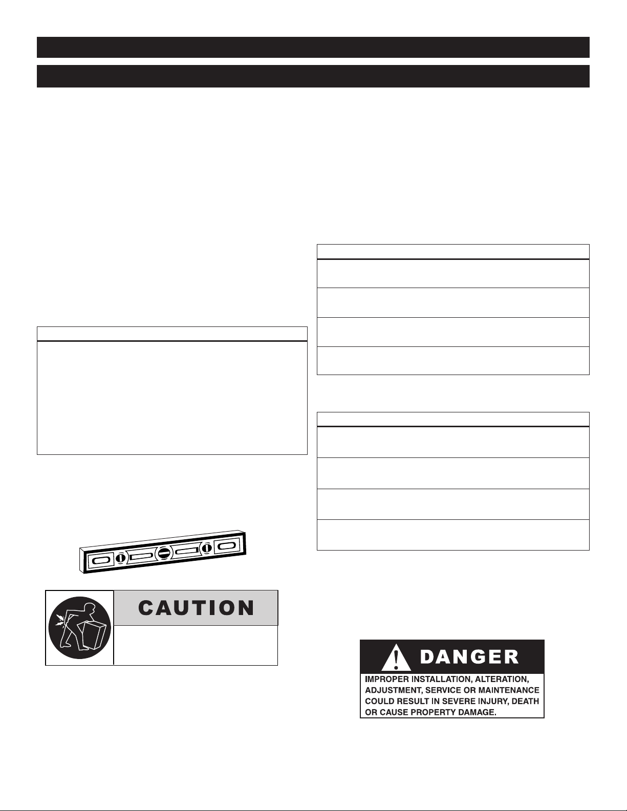
TO PREVENT PERSONAL INJURY,
USE CAUTION WHEN MOVING OR
LEVELING THIS APPLIANCE.
I N S TA L L AT I O N
1. The cabinet, complete with unattached items and
ccessories, may be delivered in one or more
a
packages. Check to ensure all accessories ordered
have been received.
2. This appliance is designed for the purpose of
maintaining hot food at a temperature for safe
consumption. The unit must be installed on a
level surface in a location that will permit the
equipment to function for its intended purpose
and allow adequate access for proper cleaning
and maintenance.
3. The appliance must not be installed in any area
where it will be affected by steam, grease,
dripping water, high temperatures, or any other
severely adverse conditions.
C L EA R AN C E R E QU I R E M E N TS
3-inches (76mm) at the back
2-inches (51mm) at the top
1-inch (25mm) at both sides
5. In order to maintain standards established
y the National Sanitation Foundation, all
b
equipment must be equipped with casters or
4" (102mm) legs to provide minimum
unobstructed space beneath the unit; or secured
flush at the bottom and the entire base sealed
with NSF approved sealant. Warranty will
become null and void if these directions are
not followed.
WE IGHT
500-1D 500-2D 500-3D
NE T 80 lb (36 kg) 115 lb (52 kg) 150 lb (68 kg)
SHIP 90 lb (41 kg) 125 lb (57 kg) 165 lb (75 kg)
On site venting for pro per airflow must also be
provided for built-in counter install ations.
4. Level the appliance from side-to-side and
front-to-back with the use of a spirit level.
WE IGHT
500-1DN 500-2DN 500-3DN
NE T 67 lb (30 kg) 100 lb (45 kg) ES T. 130 lb (59 kg) E ST.
SHIP 75 lb (34 kg) 112 lb (51 kg) 145 lb (66 kg)
#818 I n s t a ll a t i o n / Op e r a ti o n / Se r v ic e Ma n u a l• 3.
Page 5
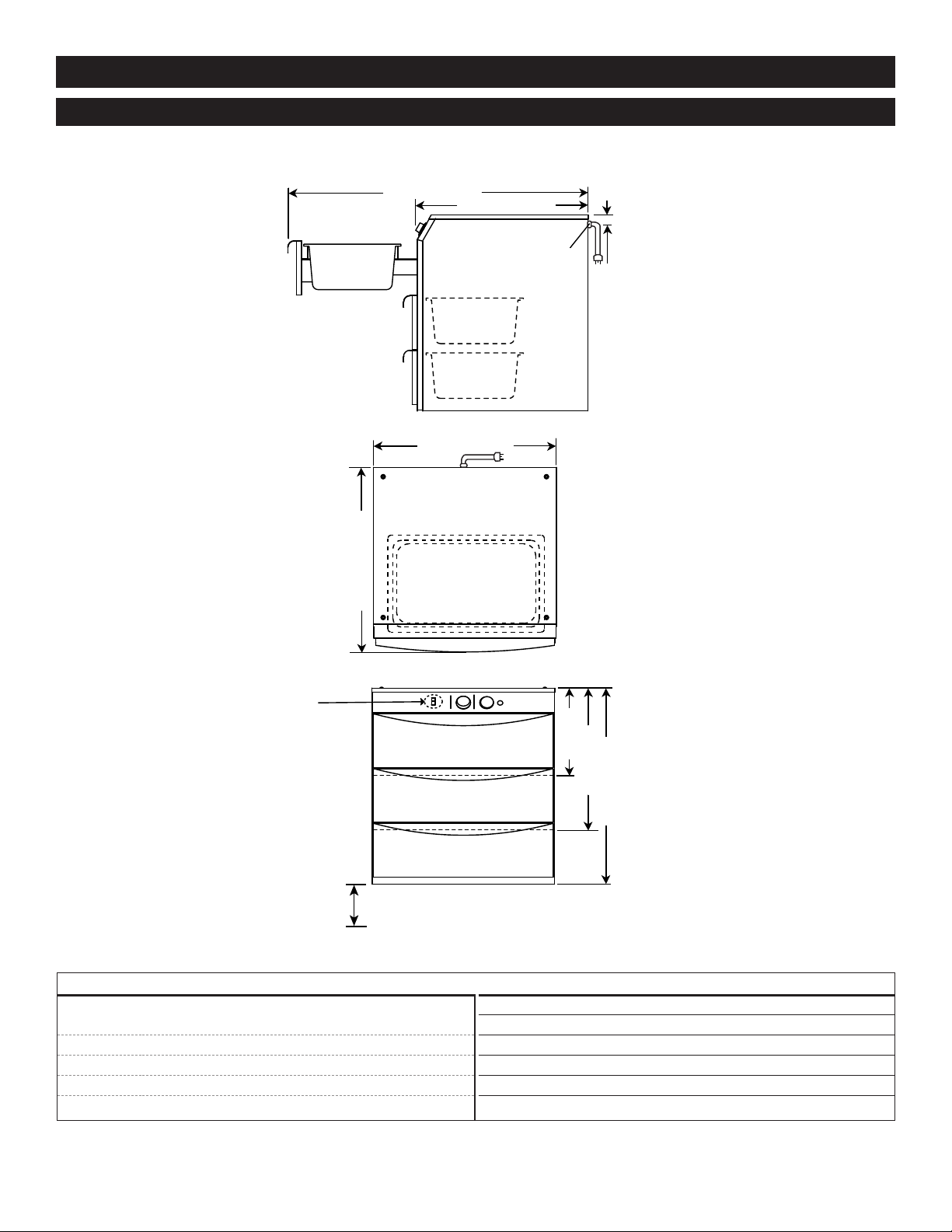
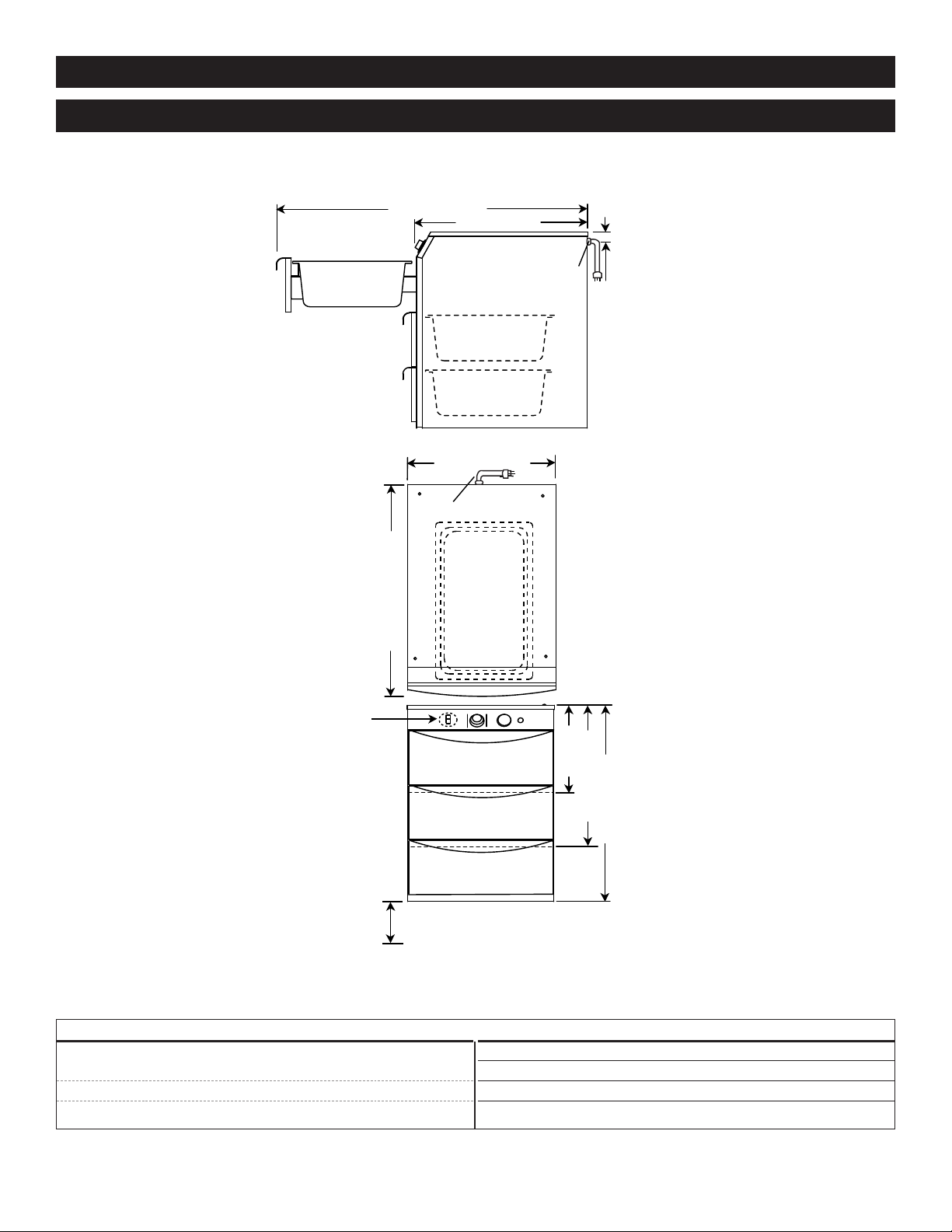
I N S TA L L AT I O N
500-1D
500-2D
500-3D
1-11/16" (42mm)
C
L
24-3/8" (618mm)
40-1/16" (1018mm)
2
2-13/16" (579mm)
11-3/4"
(298mm)
19" (482mm)
26-1/8" (663mm)
E
LECTRICAL CONNECTION
ELECTRICAL CONNECTION
H
I-LO
Switch available only on 500 -1D
and 500 -2D.
6-3/4" (171mm)
FOR LEG STAND OR CASTER STAND ASSEMBLY
24-5/8" (625mm)
HANDLE
Exterio r Di m e n sions - 500-1 D , 500-2D, 5 00-3D
O P TI O NS & A C C E S S OR I ES
Built-in Trim Kit
500-1D 44224
500-2D 44226
500-2D FOR BU2-48, BU2-72 55532
500-2D FOR BU2-96 44231
500-3D 44228
#818 I n s t a ll a t i o n / Op e r a ti o n / Se r v ic e Ma n u a l• 4.
Caster Stand Assembly 15379
Drawer Assembly with vents 55536
Leg Stand Assembly 15380
Pan, oversize, 15" x 2 0" x 5" (381 x 508 x 127 mm) PN-2123
Perforated pan grid, 15" x 20" (381 x 5 08 mm) 1231
Perforated pan grid,
12" x 20" (305 x 508 mm) 16642
Page 6
I N S TA L L AT I O N
500-1DN
500-2DN
500-3DN
1-11/16" (42mm)
C
L
16-7/16" (418mm)
50-7/8" (1291mm)
28-1/8" (714mm)
11-11/16"
(296mm)
18-7/8" (479mm)
26-3/16" (663mm)
ELECTRICAL CONNECTION
ELECTRICAL CONNECTION
H
I-LO
Switch available
only on 500-1DN
and 500-2DN.
6-3/4" (171mm)
FOR LEG STAND OR CASTER STAND ASSEMBLY
29-15/16" (761mm)
HANDLE
Exterio r Di m e n sions - 500-1 D N , 500-2DN , 5 00-3DN
O P TI O NS & A C C E S S OR I ES
Built-in Trim Kit
500-1DN 44225
500-2DN 44227
500-3DN 44229
#818 I n s t a ll a t i o n / Op e r a ti o n / Se r v ic e Ma n u a l• 5.
Caster Stand Assembly 55534
Drawer Assembly with vents 55537
Leg Stand Assembly 55535
Perforated pan grid,
12" x 20" (305mm x 508mm) 16642
Page 7
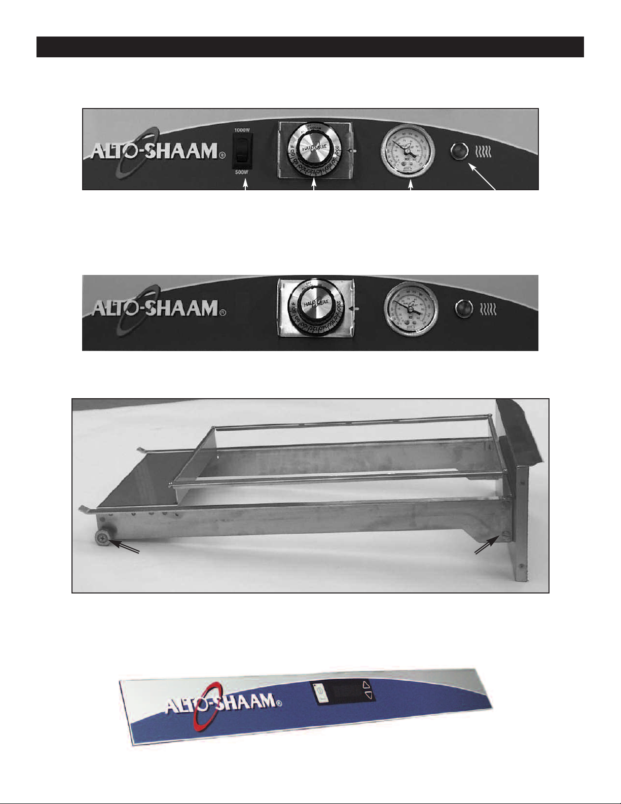
Panel Overlay
I N S TA L L AT I O N
Manual Control, 120V Unit
Panel Overlay
High Limit Switch
Thermostat Knob
Temperature
Gauge
Manual Control, 208-240V, 230V Units
Drawer Assembly
Heat Indicator
Light
Panel Overlay
Drawer Bearing
Drawer Rail
Stud & Nut
Electronic Control
#818 I n s t a ll a t i o n / Op e r a ti o n / Se r v ic e Ma n u a l• 6.
Page 8
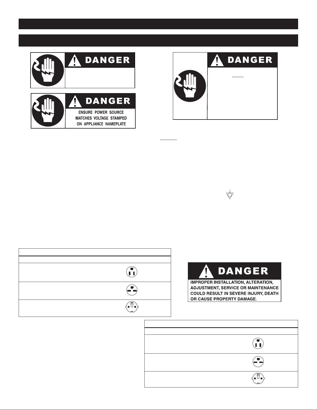
E L E C T R I C A L
To avoid electrical shock, this
appliance MUST be adequately
grounded in accordance with local
electrical codes or, in the absence of
l
ocal codes, with the current edition
o
f the National Electrical Code
ANSI/NFPA No. 70. In Canada, all
electrical connections are to be made
in accordance with CSA C22.1,
Canadian Electrical Code Part 1 or
local codes.
ELECTRICAL CONNECTIONS MUST
BE MADE BY A QUALIFIED SERVICE
TECHNICIAN IN ACCORDANCE WITH
APPLICABLE ELECTRICAL CODES.
I N S TA L L AT I O N
1. An identification tag is permanently mounted on
the cabinet.
2. Plug cabinet into a properly grounded receptacle
ONLY, positioning the unit so the power supply
cord is easily accessible in case of an emergency.
Arcing will occur when connecting or
disconnecting the unit unless all controls are in
the “OFF” position.
3. If necessary, a proper receptacle or outlet configuration as required for this unit, must be
installed by a licensed electrician in accordance
with applicable, local electrical codes.
EL ECTR ICA L - 50 0-1 D; 50 0-2 D; 50 0-3 D
VOLTAGE PHASE CYCLE/ HZ AMPS kW
120 1 60 LOW 4.0 0.5
HI GH 8.5 1.05
at 208 1 50/60 4.0 0.8
at 240 1 50/60 4.5 1.05
NEMA 5-15P
15A, 125V PLUG
NEMA
15A, 250V PLUG
FOR USA ONLY
230 V:
To prevent an electrical shock hazard between the
appliance and other appliances or metal parts in
close vicinity, an equalization-bonding stud is
provided. An equalization bonding lead must be
connected to this stud and the other appliances /
metal parts to provide sufficient protection against
potential difference. The terminal is marked with
the following symbol.
NOT E: The appliance must be connected to an
electrical circuit that is protected by an external
GFCI outlet.
6-15P
230 1 50/60 4.2 0.97
#818 I n s t a ll a t i o n / Op e r a ti o n / Se r v ic e Ma n u a l• 7.
7/7,
CEE
220-230V
PLUG
EL ECTR ICA L - 50 0-1 DN; 500- 2DN; 500 -3DN
VOLTAGE PHASE CYCLE/ HZ AMPS kW
120 1 60 LOW 4.0 0.5
HI GH 8.5 1.05
at 208 1 50/60 4.0 0.8
at 240 1 50/60 4.5 1.05
230 1 50/60 4.2 0.97
NEMA 5-15P
15A, 125V PLUG
NEMA
6-15P
15A, 250V PLUG
FOR USA ONLY
7/7,
CEE
220-230V PLUG
Page 9

I N S TA L L AT I O N
U S E R S A F E T Y IN F O R M ATI O N
This appliance is intended for use in commercial
establishments where all operators are familiar
with the purpose, limitations, and associated
hazards of this appliance. Operating instructions
and warnings must be read and understood by all
operators and users.
1. Make sure the unit is connected to the
appropriate power source.
2. Use hand protection when handling
hot items.
3. Preheat the unit for 30 minutes before use.
4. Be certain only hot foods are placed
into the unit.
BEFORE INITIAL U SE:
Before operating the unit, cle an both the interior
and exterior of the unit with a clean, da mp cloth
and mild soap solution. Rinse carefully. Clean and
install the drawer warmer pa n(s). The drawer
assembly is completely remova ble. Clean as a
sanitation measure.
HEATIN G CHARACTERISTIC S
FOO D P RODUC T T I PS
Bread and Rol l s
Breads and rol ls are traditionally difficult to hold
for prolonged periods due to th e very low
moisture content of th ese products. Fo r best
results and longest po ssible holding life, it is
recommended these pro ducts be placed in a
plastic bag while in the war m ing drawer. Breads
and rolls should be hel d at a temperature no
higher than 120° to 140°F (49° to 60°C).
Pot atoe s
— for the best results when hold ing potatoes:
1. Do not overcook .
Regardless of the temp erature at which potatoes
are cooked or what type of oven is used, it is
important that this product do es not achieve a
final inter nal prod uct temperature in excess of
195°F (91°C). Over-cooki ng will further reduce
the moisture content and conse quently , reduce
the holding life. Potatoes should be re moved
from the oven when they reach an internal
temperature of approx imately 190°F (88°C).
After they are removed from the oven, the
internal temperature will continue to increase.
The drawer warmer is equippe d with a special
heating cable. Through this Halo Heat concept,
the heating cable is mounted ag ainst th e walls of the
unit to provide an even ly appli ed heat source
controlled by a ther most at. The design an d
operational characteristics of the un it elimi nate the
need for a moisture pan or a heat circulating fan.
Through even heat appl ication , the qua lity of food
products is maintaine d up to se veral ho urs or more.
P R OD U CT C APA C I TY
20 lbs ( 9 kg)
(34 BAK ED P OTATO ES, 50 DI NNE R ROL LS )
#818 I n s t a ll a t i o n / Op e r a ti o n / Se r v ic e Ma n u a l• 8.
MA XIM UM • E ACH DRAW ER
2. Allow po t atoe s to sta biliz e b e fore pl acing
in dra wer warm e r.
When potatoes are remo ved from a conventional
high-temperature oven, they have an ex tremely
high surface temperature. If they ar e placed in
the drawer warmer wh ile they are this hot on the
outside, moisture wil l be pull ed from the inside of
the potato and condensation wi ll form on the
outside. Holding results under these conditio ns
will not be totally satisfactory. Remove potatoes
from the oven and allow the surface temperature
to stabilize before pl acing th em in the controlled
holding atmosphere of the draw er warmer.
Page 10
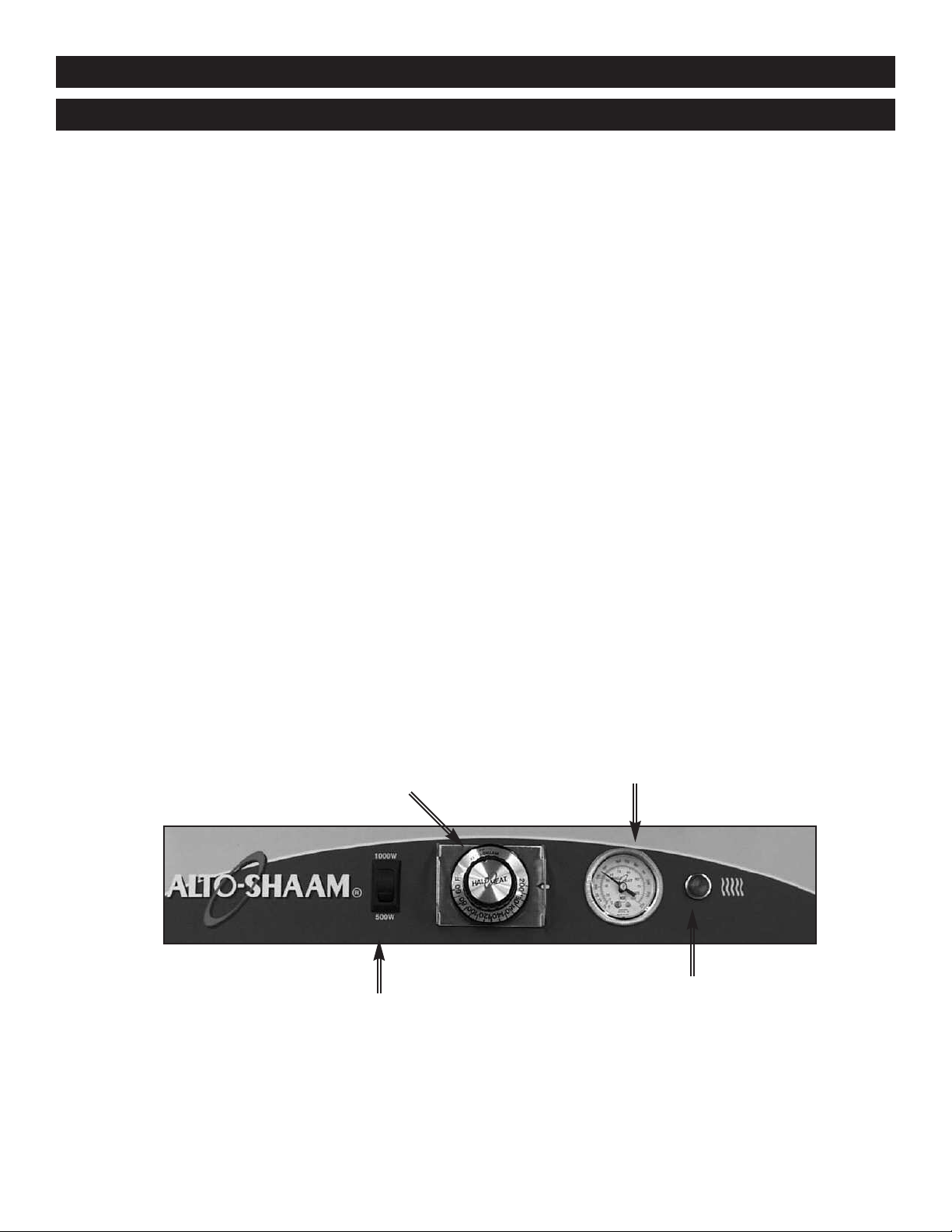
M AN U A L CO N T R O L
1. Dua l w attag e co ntro l.
The one and two drawer, 120V war mers are
provided with a HIGH/LOW power switch.
Use the HIGH position at 1000 wa tts for meats,
potatoes, and vegetables — use the LOW
position at 500 watts for bread s and rolls.
O P E R AT I O N
thermometer to make certain all food products
are at an internal te mperature range of
140° to 160°F (60° to 71 °C). All food not
within the proper temp erature range should be
heated before putting into the drawer warmer.
2. Preheat at 200 °F ( 93°C) fo r 30 min utes.
When the thermostat is turned clockwise to an
“ON” position, the indicator light wil l illumi nate
and will remain lit as long as th e unit is calling
for heat. Allow a minimum of 30 minutes of
preheating before loa ding the warmer with food.
The indicator light will go “OU T” after
approximately 30 minutes, or when the air
temperature inside the unit re aches the
temperature set by the operato r.
3. Loa d t he d rawer war mer with pan s o f
hot fo o d o nly.
The purpose of the unit is to mai ntain ho t food
at proper serving temp erature s. Only hot food
should be placed into the war mer. Bef ore
loading the unit with food, use a food
THERMOSTAT
4. Reset the the rmost at to 1 60°F (71 °C).
Check to make certain the drawer is
securely closed, and reset the ther mostat to
160°F (71°C).
THIS WILL NOT NECESSARILY BE THE
FINAL SETTING.
The proper temperatur e range for the food being
held will depend on the type and quantit y of
product. When holding food for prolong ed
periods, it is advisable to per iodical ly check the
internal temperature of eac h item to assure
maintenance of the pro per temp erature range.
TEMPERATURE
GAUGE
DUAL WATTAGE CONTROL
120V ONLY
#818 I n s t a ll a t i o n / Op e r a ti o n / Se r v ic e Ma n u a l• 9.
HEAT INDICATOR LIGHT
Page 11

°F / °C
O P E R AT I O N
POWER INDICATOR LIGHT
ON/OFF POWER KEY
- E L E C T R O N I C C O N T R O L
ED DISPLAY
L
EAT INDICATOR
H
IGHT
L
ON/OFF KEY
Press the on/off key once and the power indicator light will
illuminate. Press and hold the on/off key until the LED
display turns off (at least three seconds) and on/off indicator goes
out.
UP/DOWN ARROW KEY
The up and down arrow keys are used for a variety of settings
when selecting the holding temperature. If an arrow key is pressed
and released the display will show the current set temperature for
two seconds. If an arrow key is held (at least eight seconds), the
value will change at a rapid rate. If the arrow key is pressed and
released in rapid succession, the set temperature will change by
increments of one degree.
ENABLE/DISABLE BEEPER
A beeper sounds when an error code is displayed.
To choose between beeper on and beeper off mode, the
control must be OFF, then press and hold the down arrow
key until either "ON" or "OFF" is shown in the LED display.
Release arrow key when desired mode is displayed.
FAHRENHEIT / CELSIUS
With the control OFF, to choose between Fahrenheit and Celsius,
press and hold the up arrow key until either °F or °C is shown
in the LED display. Release key when desired setting is displayed.
The control has a four-digit LED display. When the display
is ON, it will show current holding temperature, as well as
diagnostic information.
CONTROL LOCK
The war mer controls can be locked so that no changes can
be made to the set temperature.
To lock the display, press and hold the ON/OFF key and
the Up Arrow key at the same time. The lock indicator will
illuminate. When the lock indicator is illuminated, additional
programming will not be functional other than the key
sequence required to unlock the panel.
To unlock the display, press and hold the ON/OFF key and
the Down Arrow key at the same time. The lock indicator
will extinguish. The panel keys will resume normal function.
LOCK INDICATOR
UP/DOWN
RROWS
A
1. Preheat at 200°F (93°C) for
30 minutes.
Press the ON ke y, and set the temperature
to 20 0°F (93C°) by using the UP/DOWN
arrow keys. Allow a minimum of 30
minutes preheating time before loading the
drawe r warmer with food. The L ED heat
indic ato r light will go “OUT” afte r
approxim ate ly 30 minutes preheat time, or
when the air t emperature inside the unit
reaches the temperature set by the operator.
2. Lo ad wit h pans of h ot foo d only.
The purpose of the warmer is to maintain
hot food at prop er serving tempe rat ure .
Only hot
food should be plac ed into th e
unit. Before loading with food, use a food
thermo met er to make certain all products
are at an inter n al temperature rang e of
140° to 160°F (60° to 71°C). Any food
product not within the proper t emp erature
range should be he ated before load ing into
the unit.
3. Re set th e cont rol to 1 60°F ( 71°C ).
Check to make ce rtain the d raw er is
securely closed, and res et to 160° F (71°C)
by us ing the U P/D OWN keys.
THIS WILL NOT NECE SSARILY BE T HE
FINAL SETTING.
The proper temperature range will d epe nd
on th e type a nd quantity of product. When
holdi ng food for prol onged periods, it is
advis abl e to periodic all y check the inter nal
temperat ure of each item with a food
thermo met er to assu re maintenance of the
proper temperature range of
140° to 160°F (60° to 71°C).
#818 I n s t a ll a t i o n / Op e r a ti o n / Se r v ic e Ma n u a l• 10.
Page 12

O P E R AT I O N
GENERAL HOLDING GUIDELINES
Chefs , cooks and other specialized food service
perso nne l employ vari ed methods of cooking. Proper
holdi ng temperatures f or a specific food product m ust
be based on the moisture cont ent of the p roduct,
product density, volume, and proper serv ing
tempe rat ure s. Safe hold ing temperatures mu st also
be correlated with pa latability in de termining the length
of ho lding time fo r a specifi c product.
Halo Heat maintains the maximum am ount of product
moist ure content without the addition of water, w ater
vapor, or steam. Ma intaining maxi mum natural product
moist ure preserves the natural flavor of the p rod uct and
provides a more ge nui ne taste. In addition to pr oduct
moist ure retention, the gentle properties of Halo He at
maint ain a consistent temperature thro ugh out the
cabin et without the necessity of a heat di str ibu tion fan,
thereby preventing further moisture loss du e to
evapo rat ion or dehy dra tio n.
When product is re mov ed from a h igh temperature
cooki ng environment for immediate tran sfe r into
equip men t with the lower temperature required for hot
food holding, condensati on can form on the o utside of
the product and o n the inside of plastic containers used
in self-service appli cat ion s. Allowing th e product to
release the initial steam and h eat produced by high
tempe rat ure cooking can alleviate this condition. To
preserve the safety and quality of freshly cooked foods
howev er, a maximum of 1 to 2 minutes must be the
only time period allowed for t he initial he at to be
released from the p rod uct.
Most Halo Heat h olding equipment is provided with
a t hermostat cont rol between 60° and 200°F
(16° to 93°C). If the unit is equipped w ith vents,
close the vents fo r moist holdi ng and open the vents
for crisp holding.
If th e unit i s equipped with a thermos tat indicating
a r ange of be twe en 1 and 10, use a metal-stemmed
indic ati ng ther mometer to measure the internal
tempe rat ure of the pro duct(s) being he ld. Adjust t he
thermo sta t setting t o achieve t he best overa ll setting
based on internal product temperatur e.
H O L D I N G T E M P E R A T U R E R A N G E
ME AT FA H R E N HE I T C E L S IU S
EE F RO AS T — Rare 14 0° F 60 °C
B
BE EF R OA ST — Med/Well Done 16 0° F 71 °C
BE EF B RI SK ET 16 0° — 1 75 °F 7 1° — 7 9° C
OR N BE EF 16 0° — 1 75 °F 7 1° — 7 9° C
C
PAS TR AM I 16 0° — 1 75 °F 7 1° — 7 9° C
PR IM E RI B — Rare 14 0° F 60 °C
TE AK S — Br oi le d/ Fried 14 0° — 1 60 °F 6 0° — 7 1° C
S
RI BS — B ee f or Po rk 16 0° F 71 °C
VE AL 16 0° — 1 75 °F 7 1° — 7 9° C
AM 16 0° — 17 5° F 71° — 79 °C
H
PO RK 16 0° — 1 75 °F 7 1° — 7 9° C
AM B 16 0° — 1 75 °F 7 1° — 7 9° C
L
PO UL TRY
CH IC KE N — Fr ie d/ Baked 16 0° — 1 75 °F 7 1° — 7 9° C
UC K 160 ° — 17 5° F 71 ° — 79°C
D
TU RK EY 16 0° — 1 75 °F 7 1° — 7 9° C
GE NE RA L 16 0° — 1 75 °F 7 1° — 7 9° C
IS H/ S EA FO OD
F
FI SH — B ak ed /F ri ed 16 0° — 1 75 °F 7 1° — 7 9° C
LO BS TE R 1 60 ° — 1 75 °F 71° — 7 9° C
HR IM P — Fr ie d 160° — 1 75 °F 7 1° — 7 9° C
S
BA KE D GO OD S
BR EA DS /R OL LS 12 0° — 1 40°F 49° — 60 °C
MI SC E LL AN EOU S
CA SS ER OL ES 16 0° — 1 75 °F 7 1° — 7 9° C
DO UG H — Pr oo fi ng 80 ° — 10 0° F 2 7° — 3 8° C
EG GS — Fr ie d 15 0° — 1 60 °F 6 6° — 7 1° C
FR OZ EN E NT RE ES 16 0° — 1 75 °F 7 1° — 7 9° C
HO RS D 'O EU VR ES 160° — 18 0° F 71 ° — 82 °C
PAS TA 16 0° — 1 80 °F 7 1° — 8 2° C
PI ZZ A 16 0° — 18 0° F 71 ° — 82 °C
PO TATOE S 180 °F 8 2° C
PL ATED ME AL S 1 80 °F 8 2° C
SA UC ES 1 40 ° — 20 0° F 60 ° — 93°C
SO UP 14 0° — 200° F 60° — 93 °C
VE GE TAB LE S 16 0° — 175° F 71° — 79 °C
Th e ho ld in g te mp erature s li st ed a re s ug ge st ed gu id el in es o nl y.
#818 I n s t a ll a t i o n / Op e r a ti o n / Se r v ic e Ma n u a l• 11.
Page 13

C A R E a n d CL E A N I N G
C L E A N I N G A N D P R E V E N T I V E M A I N T E N A N C E
PRO TECT I NG STAIN L ESS STEE L S URFACES
It is important to guard against corrosion in the
care of stainless steel surfaces. Harsh, corrosive,
or inappropriate chemicals can completely destroy
the protective sur face layer of stainless steel.
Abrasive pads, steel wool, or metal implements will
abrade surfaces causing damage to this protective
coating and will eventually result in areas of
corrosion. Even water, particularly hard water that
contains high to moderate concentrations of
chloride, will cause oxidation and pitting that result
in rust and corrosion. In addition, many acidic
foods spilled and left to remain on metal surfaces
are contributing factors that will corrode sur faces.
Proper cleaning agents, mater ials, an d method s
are vital to maintaining the ap pearanc e and life of
this appliance. Spilled foods should be remove d
and the area wiped as so on as pos sible but at the
very least, a minimum of once a day. Always
thoroughly rinse surfaces after using a cleaning
agent and wipe standing water as quickl y as
possible after rinsing.
CLE ANIN G AG ENTS
Use non-abrasive cleaning products designed for use
on stainless steel surfaces. Cleaning agents must be
chloride-free compounds and must not contain
quaternary salts. Never use hydrochloric acid
(muriatic acid) on stainless steel sur faces. Always use
the proper cleaning agent at the manufacturer's
recommended strength. Contact your local cleaning
supplier for product recommendations.
CLE ANIN G MAT ERIAL S
The cleaning function can usua lly be ac complis hed
with the proper cleani ng agent and a soft, clean
cloth. When more aggressive methods mu st be
employed, use a non-abrasive scouring pad on
difficult areas and ma ke certa in to scr ub with the
visible grain of sur face met al to avo id surface
scratches. Never use wire brushes, metal scour ing
pads, or scrapers to re move foo d residue.
#818 I n s t a ll a t i o n / Op e r a ti o n / Se r v ic e Ma n u a l• 12.
Page 14

C A R E a n d CL E A N I N G
AT NO TIME SHOULD THE INTERIOR OR
EXTERIOR BE STEAM CLEANED, HOSED
DOWN, OR FLOODED WITH WATER OR
LIQUID SOLUTION OF ANY KIND. DO NOT
USE WATER JET TO CLEAN.
SEVERE DAMAGE OR ELECTRICAL HAZARD
COULD RESULT.
WARRANTY BECOMES VOID IF APPLIANCE IS FLOODED.
The cleanliness and appearance of this unit will contribute considerably
to operating efficiency and savory, appetizing fo od. Good equipment
kept clean works better and lasts longer.
TH OR OU G H LY C LE AN D A ILY
1. Disconnect un it from power source, and l et cool.
2. Remove, co ver or wrap, and refrigerate food.
3. Remove d raw er pans and clean separately. The
drawe r assembly is completely removab le. Remove
from the cabinet an d clean to prevent a bui ld-up of
food residue from i nte r fering with the function of
the drawer assembly. Regular cleanin g will help
prolong the life of these p art s.
4. Clean inte rio r metal sur fac es of the unit with a
damp, clean cloth and any g ood commercial
deter gent or grease solve nt at the r eco mmended
strength . Use a pla stic scouring pa d or oven cleaner
for difficult areas. Rinse carefully t o remove all
residue and wipe dr y.
NO TE: Avoi d the use of abrasive clea ning,
compound s, chloride base d cleaners, or
clean ers containing quat ernary salts. Never
use hydrochloric acid (muriatic acid) on
stainles s steel.
5. Wipe control panel, vents, handles, and gaskets
thorough ly since these areas harbor food debris.
6. Int eri or can b e wiped with a sanitizing solution
after cleaning and rinsing. This solution must
be ap proved for u se on stai nle ss steel food
contact surfaces.
7. To help maintain t he protective fi lm coating on
polis hed stainless st eel , clean the exterior of th e
unit with a c lea ner recommended for stainless s teel
sur fac es. Spray the cleaning agen t on a c lot h and
wipe with the grai n of the stainless steel.
Alway s follow appropriat e state or lo cal health
(hygi ene ) regulations regar din g all applica ble cleaning
and sanitation requiremen ts for foodser vic e equipment.
#818 I n s t a ll a t i o n / Op e r a ti o n / Se r v ic e Ma n u a l• 13.
Page 15

S A N I TAT I O N
Food flavor and a roma are usua lly so closely related
that it is diff icu lt, if not impossible, to separate them.
There is also an important, inse par able relationship
betwe en cleanliness and food flavor. Cleanliness, top
opera tin g efficiency, an d appearance o f equipment
contribu te considerably t o savory, a ppe tizing foods.
Good equipment that is kept cl ean, works be tte r and
lasts longer.
Most food imparts i ts own p art icular aroma and many
foods also absorb e xisting odors. Unfortunately, d uri ng
this absorption, there is no disti nct ion between GO OD
and BAD odors. The majority of objectionable f lav ors
and odors troubling food service op erations are c aus ed
by ba cteria growth. Sour ness, ranc idi ty, mustiness,
stale or other OFF flavors ar e usually the result of
ger m activity.
The easiest way to insure f ull , natural f ood flavor is
through comprehensive clean lin ess. This mean s good
control of both vi sib le soil (d irt ) and invisib le soil
(germs ). A thoroug h approach to sa nitation will
provide essential clea nli ness. It wi ll assure an attractive
appea ran ce of equipme nt, along with maximum
effic ien cy and util ity . More importa ntl y, a good
sanit ati on program provides one of th e key element s
in the prevention o f food-bor ne illnesses.
A c ontrolled holding environment for prepared foods
is just one o f the important factors involved in the
preventi on of food-bor ne illnesses. Temperature
monitori ng and cont rol during receiving, storage,
preparat ion , and the service of fo ods are of eq ual
impor tan ce.
The most accurate method of meas uring safe
temperat ure s of both hot and c old foods is by inter nal
product temperature. A quality thermo met er is an
effec tiv e tool for this purpose, and should be routinely
used on all p rod uct s that requ ire holding at a specific
temperat ure .
A c omprehensive sani tat ion program sh oul d focus on
the training of st aff in basi c sanitation p roc edu res .
This includes persona l hygiene, proper handling of ra w
foods, cooking to a safe in ter nal p rod uct temperature,
and the routine mo nit oring of inte r nal temperatures
from rec eiving through se rvice.
Most food-borne i lln esses can b e prevented through
proper temperature control and a co mpr ehe nsive
program of sanitation. Both these fact ors are i mpo rtant
to bu ild quality service as the foundation of customer
satis fac tio n. Safe f ood handling p rac tic es to prevent
food-bor n e illness i s of critical importance to the health
and safety of your customers. HA CCP, an acronym for
Hazard Analysis (at) Critical Control Points, is a quality
control program of op era ting procedures t o assure food
integ rit y, quality, and safety. Taking s tep s necessary to
augme nt food safety practices are b oth cost ef fec tive
and relatively simple. While HACCP guidelines go far
beyond the scope of this manu al, additional info r mation
is available by co ntacting:
Cente r for Food Sa fety and Appl ied Nutrition
Food and Drug Ad min istration
1-888-SA FEF OOD
I N T E RN A L F O OD P R O D U C T TE MP E R A T U RE S
H O T F O O D S
DA N G ER Z O NE 4 0 ° TO 1 40° F ( 4 ° T O 6 0° C )
CR I T ICA L ZO N E 70 ° TO 1 2 0° F (2 1 ° TO 4 9° C )
SA F E ZO N E 1 4 0 ° T O 16 5 ° F ( 6 0° T O 7 4 ° C)
C O L D F O O D S
DA NGE R ZON E ABOV E 4 0° F ( ABO VE 4° C)
SA F E ZO N E 36 °F TO 40 °F ( 2 °C T O 4 °C )
F R O Z E N F O O D S
DA NGE R ZON E ABOV E 3 2° F ( ABO VE 0° C)
CR ITI CA L Z ON E 0 ° T O 3 2° F ( -18 ° TO 0° C )
SA FE ZO NE 0 °F
#818 I n s t a ll a t i o n / Op e r a ti o n / Se r v ic e Ma n u a l• 14.
OR BELOW (- 18 °C OR BELOW)
Page 16

S E R V I C E
MANUAL CONTROL
THERMO S TAT and H EAT LIGHT SEQUENCE
Whene ver the thermo sta t is tur ned “ON,” the heat indicator light will i ndicate the powe r ON/OFF condit ion of
the heating cable, and consequent ly, the cycling of the c abi net as it maintains the dialed cavity temperature. If
the light does n ot illuminate af ter normal start-up, the m ain power source, ther most at, and/or light must be
check ed. If the w arming cabinet does not h old the t emp erature as di ale d, the cali bra tion of the thermostat must
be checked. If the warmer fail s to heat or heats cont inuously with th e thermostat “OFF,” the t her mostat m ust
be initially checked for proper o peration. If thes e items ar e checked and found to be in order, a continuity an d
resistan ce check of the heating ca ble should be made. SEE CIRCUIT DIAGR AM.
THERMO S TAT CALIBRATION
The thermostat is precision calibra ted at the factory. Normal ly, no adjustm ent or recalibrat ion is necessa ry
unless the ther most at has been mishandled in transit, changed or abused w hil e in servi ce. A thermo sta t with a
sensi ng bulb operates on hydraulic pressure, consequent ly, any bendi ng of the b ulb results in a change i n its
volum e, and alters the accuracy of the ther mostat c alibration.
A t hermostat shou ld be checked or recalibrated by placing a quality, ther mal i ndi cator at the center of an empty
holdi ng cavity. DO NOT CALIBRATE WITH AN Y FOOD PRODUCT IN THE C ABI NET. Th e thermostat
shoul d be set at 140°F (60°C), and should be allowed to stabilize at that setting for a m ini mum of one hour.
Followin g temperature st abi liz ation, the c enter of the ther mal s win g of the air temperature within the c abinet
shoul d approximately c oin cid e with t he ther mostat d ial setting.
If ca libration is necessary, the calibration screw should be adjusted with g rea t care. The calibration scre w of the
thermo sta t is locat ed in the t hermostat dial shaft. With the shaft held st ationary, a minute, clockwise motion of
the calibration screw appreciably lowe rs the ther m ost at setting. A reverse, or counter-clockwis e motion
apprecia bly raises the thermostat sett ing . After a chi eving the d esi red cycling of the ther m ost at, the calibrat ion
screw must be seal ed. Place a few drops of enamel seal ant directly o n the calibratio n screw.
(RED NAIL POLISH OR EQUIVAL ENT IS ACCE PTABLE.)
T R O U B L E S H O O T I N G C H E C K L I S T • E L E C T R O N I C C O N T R O L
R e p a i r s s h o ul d b e m ad e b y a u t h o r iz e d s e r v i ce a g en t s o n l y.
TROUBLE POSSIBLE CAUSE REMEDY
Unit does not operate. Insufficient power supply. Check power source.
Defective power cord or plug. Check and replace if necessary.
No display in electronic control. Faulty power supply board. Check line voltage for 24V across
pins 7 and 8 on the power supply board and
across terminals J9 and J10 on the electronic
control.
Faulty electronic control. Replace control.
Cannot control temperature but Faulty relay Replace relay.
sensor and electronic control
checks O.K. Heating element grounded. Replace element.
Temperature readout incorrect. Dirty or faulty sensor. Check sensor at 32°F (0°C).
If Ohm reading is 100,
Faulty control. replace display.
If Ohm reading is not 100,
replace sensor.
#818 I n s t a ll a t i o n / Op e r a ti o n / Se r v ic e Ma n u a l• 15.
Page 17

S E R V I C E
Error
Code Description/Results
Possible Cause
Service Required
E-10 Air Sensor Fault (shorted)
Inoperative Oven
Air sensor is shorted.
Air sensor is defective.
Air sensor is open or has connection failure.
Need air sensor test. See below.
E
-11
A
ir Sensor Fault (open)
Inoperative Oven
E-30 Under temperature
Oven will not reach set temperature
Oven door closed? Door gasket need replacement? Preheat skipped?
Oven overloaded or has frozen product? Defective air sensor or probe?
Defective solid state relay? Bad wire connections or open heating cable?
Is the high limit switch tripped? If none of the above, call service.
E-31 Over temperature
Oven will shut down
Shorted cable? Defective solid state relay? Defective air sensor?
If none of the above, call service.
E-60 Real time clock error
Inoperative Oven
Appliance has probably been unplugged for more than 30 days. If this is the
case, it should be plugged in with the circuit breaker ON, and the appliance
displaying the E-60 on the front panel for more than 30 minutes. Once this
has been accomplished, the circuit breaker should be turned OFF, or the
appliance unplugged for approximately 10 seconds after which the appliance
should be turned ON again.
E-70 Configuration connector error
Inoperative Oven
Check control connections for loose wires. If none, control must be replaced.
E-78 Voltage low
Inoperative Oven
If 125 VAC unit, voltage is below 90 VAC. Correct.
If 208-240 VAC voltage is below 190 VAC. Correct.
E-79 Voltage high
Inoperative Oven
If 125 VAC unit, voltage is over 130 VAC. Correct.
If 208-240 VAC, voltage is over 250 VAC. Correct.
E-80 EEPROM - Function data error
Inoperative Oven
Replace control.
E-82 EEPROM - Calibration data error
Inoperative Oven
Replace control.
E-84 EEPROM - Unit ID error
Inoperative Oven
Replace control.
E-86 EEPROM - Preset data error
Inoperative Oven
Replace control.
To test air sensor:
Test air sensor by placing sensor in ice water bath and using an ohmmeter set on the ohm scale.
The reading should be 100 ohms resistance. If it is more than 2 ohms higher or lower, sensor needs
to be replaced.
T R O U B L E S H O O T I N G • EL EC T R O N I C CO N T R O L
DRAWER WARMERS - ELECTRON I C CONTROL
#818 I
n s t a lla t i o n
/Opera t i o n / S e r v i c e M a n u a l • 16.
Page 18

Wide Drawer Warmers – Service Parts
Illustrations on following pages.
artDescription
P
Manual or Electronic Control • Wide Drawer Warmers
Air Tunnel 1 1002672 1 1002672 1 1002672
Cable Replacement Kit (CB-3044) 1 4874 1 4874 1 4874
Casing Bottom 1 1002400 1 1002400 1 1002400
Casing Top 1 1002403 1 1002403 1 1002403
Casing 1 1002558 1 1002396 1 1002564
Cordset (120V) 1 CD-3232 1 CD-3232 1 CD-3232
Cordset (208/240) 1 CD-33840 1 CD-33840 1 CD-33840
Cordset (230V) 1 CD-3922 1 CD-3922 1 CD-3922
Drawer Assembly 1 55502 2 55502 3 55502
Drawer front Mounting Stud 4 ST-25019 8 ST-25019 12 ST-25019
Drawer front Mounting Nut 4 NU-2187 8 NU-2187 12 NU-2187
Drawer Bearing 6 BG-24890 12 BG-24890 18 BG-24890
Drawer Pan (
Drawer with vents 1 55536 2 55536 3 55536
Fan, Box (120V) 1 FA-3973 1 FA-3973 1 FA-3973
Fan, Box (208/240V, 230V) 1 FA-3974 1 FA-3974 1 FA-3974
Insulation, Board 3 IN-2003 3 IN-2003 3 IN-2003
Switch (230V), circuit breaker 1 SW-33487 1 SW-33487 1 SW-33487
Switch (120V), wattage 1 SW-3409 1 SW-3409 N/A
Terminal Block 1 BK-3019 1 BK-3019 1 BK-3019
Heat Indicator Light (120V) 1 LI-3027 1 LI-3027 1 LI-3027
Heat Indicator Light (208/240V) 1 LI-3025 1 LI-3025 1 LI-3025
Heat Indicator Light (230V) 1 LI-3951 1 LI-3951 1 LI-3951
Knob, Thermostat (120V, 208/240V) 1 KN-3469 1 KN-3469 1 KN-3469
Knob, Thermostat (230V ONLY)1KN-3474 1 KN-3474 1 KN-3474
Panel Overlay (120V) 1 PE-25068 1 PE-25068 1 PE-25067
Panel Overlay (208/240V, 230V) 1 PE-25067 1 PE-25067 1 PE-25067
Thermostat 1 TT-3057 1 TT-3057 1 TT-3057
Temperature Gauge 1 TH-33713 1 TH-33713 1 TH-33713
Temperature Gauge Lens Cover replacement 1 TH-33956 1 TH-33956 1 TH-33956
Beeper 1 BP-3567 1 BP-3567 1 BP-3567
Block, Sensor 1 BK-33546 1 BK-33546 1 BK-33546
Board, Power Supply 1 BA-33554 1 BA-33554 1 BA-33554
Control, Electronic 1 5000876 1 5000876 1 5000876
Panel Overlay 1 PE-25327 1 PE-25327 1 PE-25327
Relay 1 RL-33558 1 RL-33558 1 RL-33558
Sensor 1 SN-33541 1 SN-33541 1 SN-33541
Thermostat, Electronic, 230V
NOT SHOWN)1PN-25088 2 PN-25088 3 PN-25088
Manual Control Wide • Drawer Warmers
Electronic
ONLY 1 TT-33789 1 TT-33789 1 TT-33789
ty
Q
Control • Wide Drawer Warmers
00-1D
5
ty
Q
00-2D
5
ty
Q
00-3D
5
#818 I n s t a ll a t i o n / Op e r a ti o n / Se r v ic e Ma n u a l• 17.
Page 19

Narrow Drawer Warmers – Service Parts
Illustrations on following pages.
artDescription
P
anualorElectronicControl•NarrowDrawerWarmers
M
Air Tunnel 1 1002672 1 1002672 1 1002672
Cable Replacement Kit (CB-3044) 1 4874 1 4874 1 4874
Casing Bottom 1 1002794 1 1002794 1 1002794
Casing Top 1 1002798 1 1002798 1 1002798
Casing 1 1002884 1 1002837 1 1002799
Cordset (120V) 1 CD-3232 1 CD-3232 1 CD-3232
Cordset (208/240) 1 CD-33840 1 CD-33840 1 CD-33840
Cordset (230V) 1 CD-3922 1 CD-3922 1 CD-3922
Drawer Assembly 1 55509 2 55509 3 55509
Drawer front Mounting Stud 4 ST-25019 8 ST-25019 12 ST-25019
Drawer front Mounting Nut 4 NU-2187 8 NU-2187 12 NU-2187
Drawer Bearing 6 BG-24890 12 BG-24890 18 BG-24890
Drawer Pan (NOT SHOWN)1PN-25088 2 PN-25088 3 PN-25088
Drawer with vents 1 55536 2 55536 3 55536
Fan, Box (120V) 1 FA-3973 1 FA-3973 1 FA-3973
Fan, Box (208/240V, 230V) 1 FA-3974 1 FA-3974 1 FA-3974
Insulation, Board 3 IN-2003 3 IN-2003 3 IN-2003
Switch (230V), circuit breaker 1 SW-33487 1 SW-33487 1 SW-33487
Switch (120V) wattage 1 SW-3409 1 SW-3409 N/A
Terminal Block 1 BK-3019 1 BK-3019 1 BK-3019
Manual Control • Narrow Drawer Warmers
Heat Indicator Light (120V) 1 LI-3027 1 LI-3027 1 LI-3027
Heat Indicator Light (208/240V) 1 LI-3025 1 LI-3025 1 LI-3025
Heat Indicator Light (230V) 1 LI-3951 1 LI-3951 1 LI-3951
Knob, Thermostat (120V, 208/240V) 1 KN-3469 1 KN-3469 1 KN-3469
Knob, Thermostat (230V ONLY)1KN-3474 1 KN-3474 1 KN-3474
Panel Overlay (120V) 1 PE-25014 1 PE-25014 1 PE-25013
Panel Overlay (208/240V, 230V) 1 PE-25013 1 PE-25013 1 PE-25013
Thermostat 1 TT-33626 1 TT-33626 1 TT-33626
Temperature Gauge 1 TH-33713 1 TH-33713 1 TH-33713
Temperature Gauge Lens Cover replacement 1 TH-33956 1 TH-33956 1 TH-33956
Electronic
Beeper 1 BP-3567 1 BP-3567 1 BP-3567
Block, Sensor 1 BK-24427 1 BK-24427 1 BK-24427
Board, Power Supply 1 BA-33554 1 BA-33554 1 BA-33554
Control, Electronic 1 5000876 1 5000876 1 5000876
Panel Overlay 1 PE-25326 1 PE-25326 1 PE-25326
Relay 1 RL-33558 1 RL-33558 1 RL-33558
Sensor 1 SN-33541 1 SN-33541 1 SN-33541
Thermostat, Electronic, 230V only 1 TT-33789 1 TT-33789 1 TT-33789
ty
Q
Control • Narrow Drawer Warmers
00-1DN
5
ty
Q
5
00-2DN
ty
Q
00-3DN
5
#818 I n s t a ll a t i o n / Op e r a ti o n / Se r v ic e Ma n u a l• 18.
Page 20

S E R V I C E
500-3D • Manual control • top removed
INDICATOR LIGHT
LI-3027
LI-3025
LI-3951
THERMOSTAT
TT-3057
TT-33626
THERMOMETER
TH-33713
INSULATION
IN-2003
WIRING
DIAGRAM
HEATING ELEMENT
CONNECTIONS
TERMINAL BLOCK
BK-3019
ELECTRIC CORD
CD-3232
CD-33840
CD-3922
#818 I n s t a ll a t i o n / Op e r a ti o n / Se r v ic e Ma n u a l• 19.
AIR TUNNEL 1002672
(EXHAUST FAN INSIDE)
FA-3973
FA-3974
Page 21

S E R V I C E
500-3D • Electronic control • top removed • 230V
CONTROL #5000876 WITHOUT SCI • CONTROL #5000877 WITH SCI
WIRING
DIAGRAM
HEATING
ELEMENT
CONNECTIONS
SENSOR WIRE
(WHITE)
BEEPER
BP-3567
RELAY
RL-33558
POWER SUPPLY
BA-33554
TERMINAL BLOCK
-3019
BK
AIR TUNNEL
(EXHAUST FAN INSIDE)
FA-3973, FA-3974
INSULATION
IN-2003
1002672
BREAKER SWITCH
SW-33487
THIS PHOTOGRAPH IS AN
ENLARGEMENT OF THE CIRCLED
AREA ABOVE.
ELECTRIC CORD
CD
-3232, CD-33840, CD-3922
#818 I n s t a ll a t i o n / Op e r a ti o n / Se r v ic e Ma n u a l• 20.
CORD
BUSHING
BU-3964
Page 22

S E R V I C E
INSULATION
IN-2003
500-3D
Heat Cable Wrap
HEAT ELEMENT
CABLE
CB-3044
500-3D
Interior
THERMOMETER
CAPILLARY
BEARINGS
THERMOSTAT
CAPILLARY
#818 I n s t a ll a t i o n / Op e r a ti o n / Se r v ic e Ma n u a l• 21.
Page 23

#818 I n s t a ll a t i o n / Op e r a ti o n / Se r v ic e Ma n u a l• 22.
Page 24

#818 I n s t a ll a t i o n / Op e r a ti o n / Se r v ic e Ma n u a l• 23.
Page 25

#818 I
n s t a lla t i o n
/Opera t i o n / S e r v i c e M a n u a l • 24.
Page 26

#818 I n s t a ll a t i o n / Op e r a ti o n / Se r v ic e Ma n u a l• 25.
Page 27

#818 I n s t a ll a t i o n / Op e r a ti o n / Se r v ic e Ma n u a l• 26.
Page 28

#818 I
n s t a lla t i o n
/Opera t i o n / S e r v i c e M a n u a l • 27.
Page 29

#818 I
n s t a lla t i o n
/Opera t i o n / S e r v i c e M a n u a l • 28.
Page 30

#818 I n s t a ll a t i o n / Op e r a ti o n / Se r v ic e Ma n u a l• 29.
Page 31

#818 I n s t a ll a t i o n / Op e r a ti o n / Se r v ic e Ma n u a l• 30.
Page 32

#818 I n s t a ll a t i o n / Op e r a ti o n / Se r v ic e Ma n u a l• 31.
Page 33

All Alto-Shaam equipment
is sold F.O.B. shipping
point, and when accepted
by the carrier, such
shipments become the
property of the consignee.
Should damage occur in shipment, it is a matter
between the carrier and the consignee. In such cases, the
carrier is assumed to be responsible for the safe delivery
of the merchandise, unless negligence can be established
on the part of the shipper.
1. Make an immediate inspection while the equipment
is still in the truck or immediately after it is moved to
the receiving area. Do not wait until after the
material is moved to a storage area.
2. Do not sign a delivery receipt or a freight bill until
you have made a proper count and inspection of all
merchandise received.
3. Note all damage to packages directly on the carrier’s
delivery receipt.
4. Make certain the driver signs this receipt. If he
refuses to sign, make a notation of this refusal on
the receipt.
5. If the driver refuses to allow inspection, write the
following on the delivery receipt:
Drive r re fus es to allo w ins pe ctio n o f
co ntaine rs fo r v isib le d a ma ge .
6. Telephone the carrier’s office immediately upon
finding damage, and request an inspection. Mail a
written confirmation of the time, date, and the
person called.
7. Save any packages and packing material for further
inspection by the carrier.
8. Promptly file a written claim with the carrier and
attach copies of all supporting paperwork.
We will continue our policy of assisting our
customers in collecting claims which have been properly
filed and actively pursued. We cannot, however, file any
damage claims for you, assume the responsibility of any
claims, or accept deductions in payment for such claims.
Alto-Shaam, Inc. warrants to the original purchaser that any
original part that is found to be defective in material or workmanship
will, at Alto-Shaam's option, subject to provisions hereinafter stated,
be replaced with a new or rebuilt part.
The labor warranty remains in effect one (1) year from installation
o
r fifteen (15) months from the shipping date, whichever occurs first.
Alto-Shaam will bear normal labor charges performed during standard
business hours, and excluding overtime, holiday rates or any
additional fees.
The parts warranty remains in effect for one (1) year from
installation or fifteen (15) months from the shipping date, whichever
o
ccurs first.
However, the heating element on Halo Heat
®
cook/hold ovens
and the refrigeration compressor on Alto-Shaam Quickchillers
™
are
warranted for a period of five (5) years from installation. The labor
warranty is the same as stated above; namely, for one (1) year from
installation or fifteen (15) months from the shipping date, whichever
occurs first.
THIS WARRANTY DOES NOT APP LY TO:
1. Calibration.
2. Replacement of light bulbs and/or the replacement of display
case glass due to damage of any kind.
3. Equipment damage caused by accident, shipping, improper
installation or alteration.
4. Equipment used under conditions of abuse, misuse, carelessness
or abnormal conditions including, but not limited to, equipment
subjected to harsh or inappropriate chemicals including, but not
limited to, compounds containing chloride or quaternary salts, poor
water quality, or equipment with missing or altered serial numbers.
5. Damage incurred as a direct result of poor water quality,
inadequate maintenance of steam generators and/or surfaces
affected by water quality. Water quality and required maintenance
of steam generating equipment is the responsibility of the
owner/operator.
6. Damage caused by use of any cleaning agent other than
Alto-Shaam's Combitherm
®
Cleaner including, but not limited to,
damage due to chlorine or other harmful chemicals. Use of
Alto-Shaam's Combitherm®Cleaner on Combitherm®ovens is
highly recommended.
7. Any losses or damage resulting from malfunction, including loss
of product or consequential or incidental damages of any kind.
8. Equipment modified in any manner from original model,
substitution of parts other than factory authorized parts,
removal of any parts including legs, or addition of any parts.
This warranty is exclusive and is in lieu of all other warranties,
expressed or implied, including the implied warranties of
merchantability and fitness for a particular purpose. In no event
shall Alto-Shaam be liable for loss of use, loss of revenue or profit,
or loss of product, or for any indirect or consequential damages.
No person except an officer of Alto-Shaam, Inc. is authorized to
modify this warranty or to incur on behalf of Alto-Shaam any other
obligation or liability in connection with Alto-Shaam equipment.
ALTO-SHAAM, INC.
TRANSPORTATION
DAMAGE and CLAIMS
®
RECORD THE MODEL AND SERIAL NUMBER OF THE APPLIANCE FOR EASY REFERENCE.
ALWAYS REFER TO BOTH MODEL AND SERIAL NUMBER IN ANY CONTACT WITH ALTO-SHAAM REGARDING THIS APPLIANCE.
Model: _______________________________________________Date Installed: __________________________________________________________
Voltage: ______________________________________________ Purchased From: _______________________________________________
Serial Number: _______________________________________ _______________________________________________________________________
W164 N9221 Water Street●P.O. Box 450●Menomonee Falls, Wisconsin 53052-0450●U.S.A.
PHONE: 262.251.3800 • 800.558-8744 USA/CANADA FAX: 262.251.7067 • 800.329.8744 U.S.A. ONLY
WEBSITE: www.alto-shaam.com
PRINTED IN U. S . A .
LIMITED
WARRANTY
 Loading...