


Alto Shaam 1000-TH-I-STD Operators Manual
#837A • 3/2005
PRINTED IN U. S .A .
INSTALLATION
OPERATION
AND
MAINTENANCE
MANUAL
LOW TEMPERATURE
OVEN
COOK
HOLD
MODEL:
1000-TH-I/HD
1000-TH-I/HD/D
1000-TH-I/HD/PT
1000-TH-I/STD
1000-TH-I/STD/D
W164 N9221 Water Street • P.O. Box 450 • Menomonee Falls, Wisconsin 53052-0450 USA
PHONE: 262.251.3800 FAX: 262.251.7067 • 800.329.8744 U.S.A. ONLY WEBSITE:
800.558-8744 USA/CANADA 262.251.1907 INTERNATIONAL www.alto-shaam.com

#837A O&C MANUAL•1000-TH-I FAMILY
PG. 1
Unpacking and Setup
The Alto-Shaam Cooking and Holding
Oven has been thoroughly tested, checked for
calibration, and inspected to ensure only the
highest quality oven is provided. When you
receive your oven, check for any possible
shipping damage and report it at once to the
delivering carrier.
(See Transportation Damage
and Claims section of this manual.)
The oven, complete with unattached items
and accessories, may be delivered in one or more packages.
Check to insure that all the following items have been
received with each standard unit:
2 Ea. Drip Pans 1 Ea. External Drip Tray
4 Ea. Oven Side Racks 4 Ea. Casters
6 Ea. Wire Shelves 16 Ea. Caster Mtg. Screws
The heavy duty models have the full perimeter bumper
and casters installed at the factory.
Save all the information and instructions packed inside
the oven. Complete and return the warranty card to the
factory as soon as possible to insure prompt service in the
event of a warranty parts and labor claim.
Note: Any and all claims for warranty must include the
full model and serial number of the unit.
This cook and hold oven is designed for the purpose of
heating food to its proper temperature and maintaining the
hot food at a temperature for safe consumption. It must be
installed in a location that will permit it to function for its
intended purpose and allow adequate access for proper
cleaning and maintenance.
Oven Characteristics
The oven is equipped with a special, high-heat-density,
heating cable. Through the Halo Heat concept, the heating
cable is mounted against the walls of the cooking cavity to
provide an evenly applied heat source controlled by a
thermostat. The design and operational characteristics of
the oven eliminates the need for a moisture pan or a heat
circulating fan. Through even heat application, the quality
of a food product is maintained up to several hours.
Electrical Installation
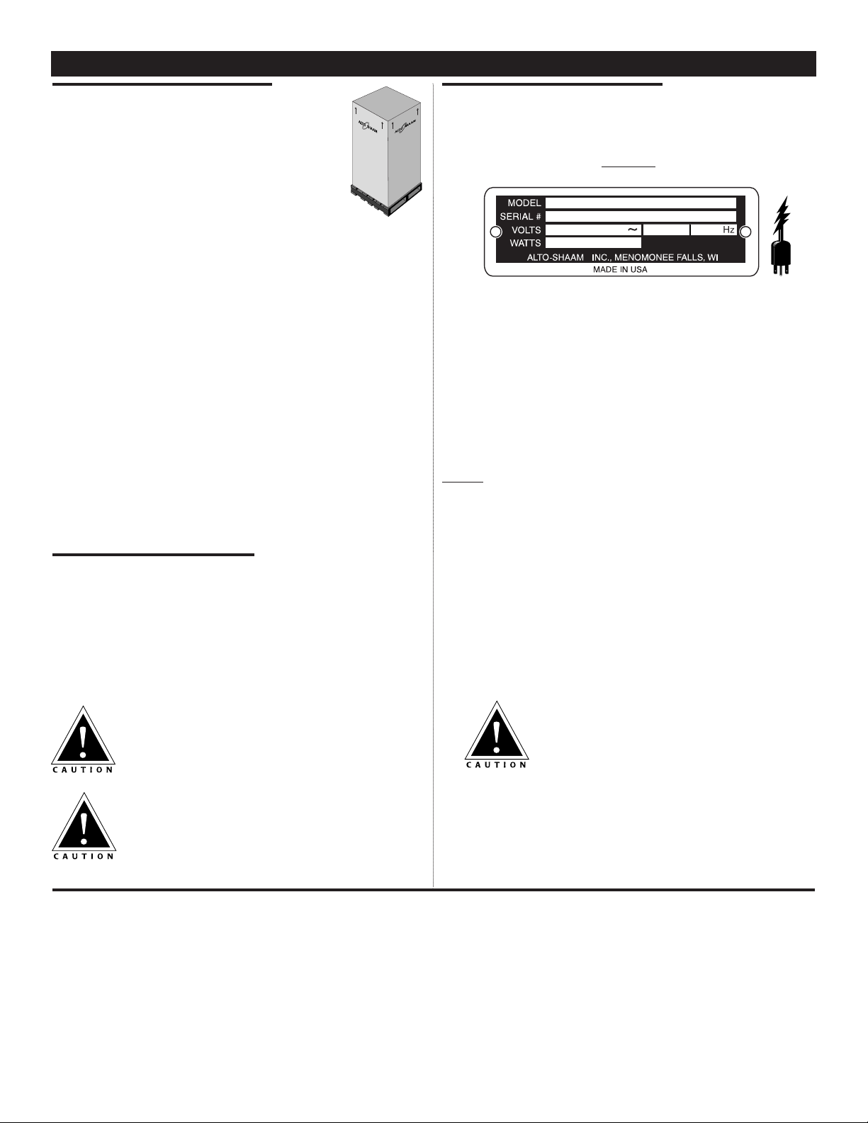
1.An identification tag is permanently mounted on
the oven.
SAMPLE
2.All models at 208/240 volts are dual rated units with a
conversion switch mounted under an access cover on the
rear of the oven, near the power cord.
With the voltage conversion switch in the 200 volt
through 208 volt (
UPPER) position, the oven will
function properly with a source voltage of between 200
volts and 208 volts.
With the voltage conversion switch in the 220-240 volt
(
LOWER) position, the unit will function properly with a
source voltage of between 220 volts and 240 volts.
NOTE: All 208/240 volt units are shipped from the
factory with the voltage conversion switch in the
220-240 volt position. Again, ensure that the
voltage conversion switch position and the
available power source match.
3. If necessary, a proper receptacle or outlet must be
installed by a licensed electrician in accordance with
applicable local electrical codes. This oven must be
grounded in accordance with the requirements of
the National Electrical Code or applicable local
country codes.
Ensure power source matches voltage
stamped on oven nameplate.
At no time should the oven be steamed cleaned,
washed down, or flooded with water or liquid
solution. Do not use water jet to clean. Severe
damage or electrical hazard could result.
Disconnect oven from power source before
cleaning or servicing.
Cold food for rethermalization or reheating
must never be added to the oven while hot
food is being held.
®
®
INSTALLATION
Start-Up
For the best service, the oven should be installed level. The oven should NOT be installed in any area where it may be
affected by steam, grease, dripping water, high temperatures or any other severely adverse conditions.
1. Before operating the oven, clean both the interior and exterior of the unit with a damp cloth and mild soap solution.
Rinse carefully.
2. Install the external drip tray on the lower front of the oven. See installation instructions located in this manual.
3. Clean and install the oven side racks and oven shelves. Shelves should be positioned with the curved end up and
toward the back of the oven. Insert the drip pan on the interior bottom surface of the oven.
4. Before operating the unit with product, become familiar with the operation of the controls. Read the following
“
General Operation” section of this manual and operate the various control functions.
PATENT NOS.
3521030
4595247
®
PH
#837A O&C MANUAL•1000-TH-I FAMILY
PG. 2
INSTALLATION
Thermostat/Indicator Light Sequence
Whenever the start-up procedure has been
completed, the indicator light will indicate the power
ON/OFF condition of the heating cable and
consequently, the cycling of the oven as it maintains
the dialed cavity temperature. If the light does not
indicate after normal start-up, the main power source,
the main power breaker, and/or the oven control
circuitry must be checked. If a oven compartment does
not hold the temperature as dialed, the calibration of
the thermostat must be checked. (SEE THE PARAGRAPH
ON THERMOSTAT CALIBRATION
.) If a cooking
compartment fails to heat or heats continuously with
the thermostat off, the thermostat must be initially
checked for proper operation. If all is in order, a
continuity and resistance check of the heating cable
should be made. (SEE THE CIRCUIT DIAGRAM.)
Thermostat Calibration
At 250° F (121° C) COOK
and 140° F (60° C) HOLD
The thermostat is precision calibrated at the
factory. Normally, no adjustment or recalibration is
necessary unless the thermostat has been mishandled in
transit or changed or damaged while in service. A
thermostat with a sensing bulb operates on hydraulic
pressure. Consequently, any bending of the bulb
results in a change in its volume and displaces the
accuracy of the thermostat calibration.
A thermostat should be checked or recalibrated by
placing a quality temperature indicator at the center of
an empty oven cavity. DO NOT CALIBRATE WITH
FOOD PRODUCT IN THE OVEN. The temperature
must be allowed to stabilize at one particular setting for
at least two hours. Following temperature stabilization,
the center of the thermal swing of the cavity
temperature should approximately coincide with the
thermostat dial setting.
The calibration screw of the thermostat is located
in the dial shaft. With the shaft held stationary, a
minute clockwise motion of the calibration screw
appreciably lowers the thermostat setting while a
reverse motion results in the opposite condition. After
achieving the desired cycling of the thermostat, the
calibration screw must be sealed in place with a few
drops of sealant.
[RED NAIL POLISH OR EQUIVALENT IS ACCEPTABLE.]
Bumpers
➥ Corner Guards. . . . . . . . . . . . . . . . . . . . . . . . . . 5221
➥ Full Perimeter . . . . . . . . . . . . . . . . . . . . . . . . . . 4994
Carving Holder
➥ Prime Rib . . . . . . . . . . . . . . . . . . . . . . . . . . HL-2635
➥ Ship Round . . . . . . . . . . . . . . . . . . . . . . . . . . . . 4459
Door Lock with Key . . . . . . . . . . . . . . . . . . . . LK-22567
Drip Pan
➥ Standard with Drain . . . . . . . . . . . . . . . . . . . . . 14824
➥ Extra Deep . . . . . . . . . . . . . . . . . . . . . . . . . . . . 1115
Legs, 6" (152mm) . . . . . . . . . . . . . . . . . . . . . . . . . 5205
Pan Grid, Wire
➥ 18" x 26" Pan Insert . . . . . . . . . . . . . . . . . . . PN-2115
Security Panel with Key Locking Handle
➥ Upper Control . . . . . . . . . . . . . . . . . . . . . . . . . . 4372
➥ Center Control. . . . . . . . . . . . . . . . . . . . . . . . . . 4368
Shelves
➥ S/S Flat Wire . . . . . . . . . . . . . . . . . . . . . . . . SH-2325
➥ S/S Rib Rack . . . . . . . . . . . . . . . . . . . . . . . . SH-2773
Thermostat, Cooking
➥ 250°F Limit. . . . . . . . . . . . . . . . . TT-3978/KN-3491
OPTIONS AND ACCESSORIES
At no time should the oven
interior or exterior be steam
cleaned, hosed down, or flooded
with water or liquid solution. Do
not use water jet to clean. Severe
damage or electrical hazard could
result voiding the warranty.
#837A O&C MANUAL•1000-TH-I FAMILY
PG. 3
OPERATION
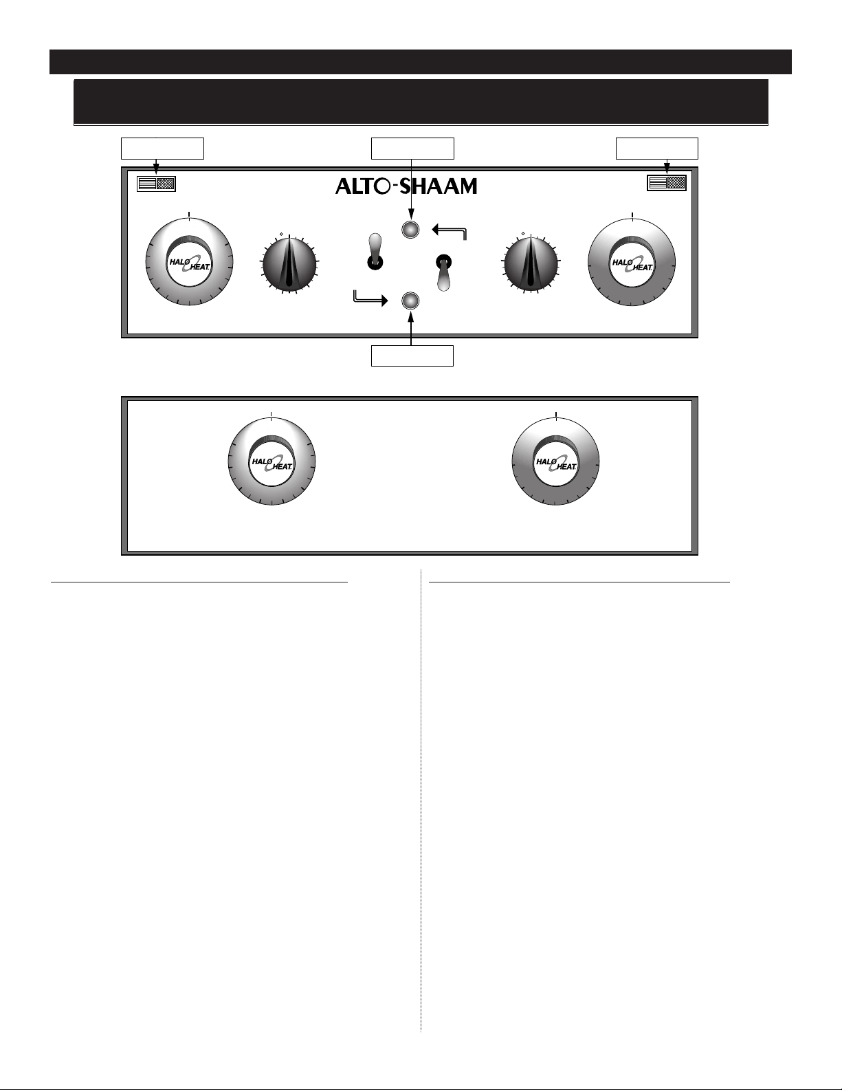
UPPER COOKING COMPARTMENT
1. Turn upper oven POWER SWITCH “ON.”
— Upper oven POWER “ON” INDICATOR LIGHT
will illuminate and will remain lit as long as the
upper oven Power Switch is in the “ON” position.
2. Set the upper oven HOLD THERMOSTAT to the
required holding temperature.
— Upper oven HOLDING INDICATOR LIGHT will
illuminate as the Hold Thermostat calls for heat.
This process will continue as long as the upper
oven Power Switch and Hold Thermostat are in
the “ON” position.
3.Set upper oven COOK THERMOSTAT to the
required cooking temperature
4.To preheat the upper oven, activate the Cook
Thermostat by turning the upper oven COOKING
TIMER clockwise.
— Upper oven COOKING INDICATOR LIGHT and
HOLDING INDICATOR LIGHT will illuminate as
the Cook Thermostat calls for heat. This process
will continue until the upper oven Cooking Timer
cycles or is turned to the “OFF” position.
LOWER COOKING COMPARTMENT
1. Turn lower oven POWER SWITCH “ON.”
— Lower oven POWER “ON” INDICATOR LIGHT
will illuminate and will remain lit as long as the
lower oven Power Switch is in the “ON” position.
2. The lower oven HOLD THERMOSTAT is located on
the lower control panel. Set the lower oven HOLD
THERMOSTAT to the required holding temperature.
— Lower oven HOLDING INDICATOR LIGHT will
illuminate as the Hold Thermostat calls for heat.
This process will continue as long as the lower
oven Power Switch and Hold Thermostat are in
the “ON” position.
3. The lower oven COOK THERMOSTAT is located on
the lower control panel. Set the lower oven COOK
THERMOSTAT to the required cooking temperature.
4. To preheat the lower oven, activate the Cook
Thermostat by turning the lower oven COOKING
TIMER clockwise.
— Lower oven COOKING INDICATOR LIGHT and
HOLDING INDICATOR LIGHT will illuminate as
the lower oven Cook Thermostat calls for heat.
This process will continue until the lower oven
Cooking Timer cycles or is turned to the “
OFF”
position.
These instructions are basic operational guidelines only. For complete instructions, see the
Cooking Guidelines Booklet packed with the oven.
INDICATOR LIGHTS
LOWER OVEN
HOLD COOK
LOWER OVEN
ELEMENT
OFF
60 F
0
8
100
120
HOLD TEMP
UPPER OVEN
POWER ON LIGHT
UPPER OVEN
®
COOK TIMER
LOWER OVEN
OFF
1
200
180
160
1
4
0
12
11
10
9
8
67
TURN PAST TIME DESIRED
THEN SET TIME
OFF
60 F
0
8
100
HOLD TEMP
LOWER OVEN
200
180
160
1
4
0
120
5
2
3
4
ON
OFF
LOWER OVEN
UPPER OVEN
POWER ON LIGHT
LOWER OVEN
ON
OFF
COOK TIMER
UPPER OVEN
OFF
1
12
11
10
9
8
TURN PAST TIME DESIRED
THEN SET TIME
5
67
OFF
100 F
150
0
0
2
COOK TEMP
LOWER OVEN
2
4
3
2
5
0
100 F
150
COOK TEMP
UPPER OVEN
350
300
INDICATOR LIGHTS
UPPER OVEN
HOLD COOK
UPPER OVEN
ELEMENT
OFF
350
3
00
2
5
0
0
0
2