

Page 1

APX1000
QUICKSTART GUIDE
ENGLISH
Page 2

p
QUICKSTART GUIDE (ENGLISH)
BOX CONTENTS
APX1000
Power cable
Quickstart Guide
Safety & Warranty Information Booklet
QUICK SETUP
1. Make sure all items listed in the BOX CONTENTS section are included in the box.
2. READ SAFETY & WARRANTY INFORMATION BOOKLET BEFORE USING THE PRODUCT.
3. Study the connection diagram in this guide.
4. Place all devices in an appropriate position for operation.
5. Make sure all devices are turned off and all faders and gain knobs are set to "zero."
6. Connect all sound sources' outputs to amplifier inputs as indicated in the diagram.
7. Connect the amplifier outputs to speakers.
8. Plug all devices into an appropriate power source.
9. Switch everything on in the following order:
• Sound sources (i e. microphones, turntables, CD players, etc.)
• Mixer
• Amplifier
• Speakers
10. When turning powering down, turn everything off in the following order:
• Speakers
• Amplifier
• Mixer
• Sound sources
CONNECTION DIAGRAM
USH
PUSH
Do NOT make any connections
when any device is powered on.
Note
Please see the SPEAKER
CONNECTION section for important
setu
information.
2
Page 3
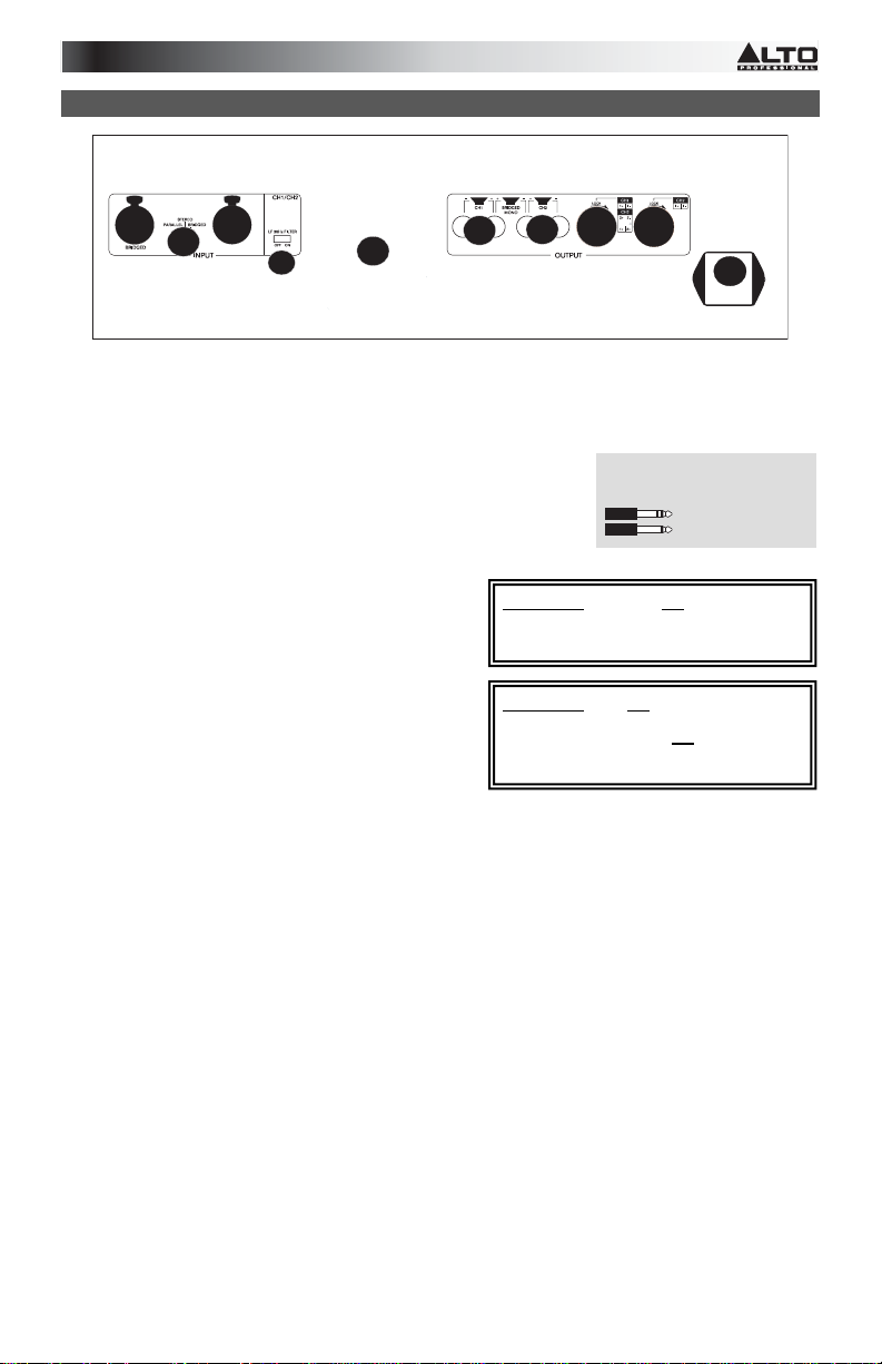
REAR PANEL DIAGRAM
PUSH
3
1. COOLING FAN- This fan secures cooling for the amplifier. The airflow is from fro nt to rear. The fan speed is
electronically regulated depending on the temperature of t he power devices. Do not block these fan grills or
mount the amplifier in an enclosed rack, which could cause the amplifier to overheat.
2. LOW PASS FILTER – This switch activates the built-in low cut filter. All audio below 30 Hz will be removed
from the output signal.
3. BALANCED COMBO INPUTS – Connect your mixer to the balanced
XLR or balanced 1/4" input for that channel.
4. OUTPUT MODE SWITCH – The APX 1000 presents three oper ating
modes:
Stereo Mode
In this mode, CH 1 and CH 2 operate independently (as a normal
stereo amplifier) The CH 1 input signal will be output from the CH 1 output connector, and CH 2 input
signal will be output from the CH 2 output
connector.
Parallel Mono Mode
In this mode, CH 1 input signal will be output from
the output connectors of both
channels.
Bridged Mode
In this mode, CH 1 input signal will be output from
5. CHANNEL OUTPUTS – Connect your speakers' input
6. POWER IN – Connect the cable to a standard wall outlet. Be sure the supplied voltage matches the required
the bridge-mono output connector.
jacks to these outputs.
• For the binding posts, red is the positive signal
and black is the negative signal. Please make
sure to respect the speaker polarity when using bindi ng post. Turn off the unit before connec ting an
audio signal to the binding post to avoid any electric shock!
• The SPEAKON outputs are specifically designed to c onnect to high po wer speakers. The correct polari ty
is secured automatically. They prevent shock hazard and they lock-in securely. Please see the
SPEAKER CONNECTION section to properly and safely connect your speakers.
voltage of the amplifier. Do not connect the amplifier to an outlet that does not match the required voltage;
doing so could damage the amplifier.
PUSH
3
4
2
1
5
5
5
5
6
How do I know if my 1/4" cables
are balanced?
WARNING Do not adjust the
STEREO/MONO BR DGE SWITCH when the
amplifier is on.
WARNING Do not allow any wires of
adjacent terminals to come in contact with
each other. Also, do not
positive (red) output to chassis ground.
3
BALANCED
UNBALANCED
connect either
Page 4

FRONT PANEL DIAGRAM
7
4
3
5
6
6
1
7
2
1. POWER SWITCH – Turns the amplifier on/off.
2. POWER LED – Illuminates when the amplifier is on.
3. LED METERS – Indicates the audio signal level. This LED will light up when the signal at the output is at least -
4. CLIP – The red "Clip" light indicates the signal is distorting or "clipping," which occurs when the volume
5. PROT – The red "Prot" light indicates the output for that channel has turned off to protect your ampli fier and
6. CHANNEL GAIN – This knob controls the channel's output signal.
7. COOLING VENTS – These vents help to cool the internal parts of the amplifier when in use. Do no t block
20 dB.
exceeds the amplifier's maximum output. This LED will flash when distortion reaches a level of 0.5%.
Consistent clipping can damage your amplifier and speakers. If the signal is regularly clipping, reduce the
volume of the amplifier. If it is lit about half the time, the amplifier channel's thermal protection will cause
the channel to shut down within a few minutes.
speakers, which can be damaged by excessive volume r esulting in clipping. If the meters' r ed lights are
illuminating, decrease the levels of your CHANNEL GA N knobs.
these vents, and keep the vents clean at all times.
SPEAKER CONNECTION
WARNING
• Do not make any connections when any device is powered on.
• Do not allow the wires from terminals to come in contact with each other.
• Do not connect either positive (red) output to chassis ground.
SHORT CIRCUIT PROTECTION
Output short circuit protection protects the output devices of the amplifier from short circuits and stressful loads . If
your speaker lines short, the amplifier automatically detects t his problem an d discontinues operation for that channel.
(If one channel's short circuit protection is activated, the other channel will continue to operate normall y.) During
short circuit protection, the "Clip" and "Protect" LED s will light simultaneously, and all output from
that channel will stop.
Short Circuit Protection can often be traced back to the signal
output line (i.e., the speaker line). Check the line from the
output terminal of the amplifier to the speaker. If this line is still
good, check the internal speaker connections and
components. (A short circuit can often be traced to a bad
cable or a bad speaker component and is rarely traced to the amplifier itself.)
Bare Wire Connections
When connecting your speakers to the amplifier using bare wires, follow these steps:
1. Unscrew the red and black caps of the binding posts. (Be s ure not to completely remove or unscrew the red
and black caps.)
2. Strip back the wire insulation 1/2" (13mm).
3. Insert the bare wire into the hole exposed under the binding post cap.
4. After inserting the wire, screw the binding post cap down on the wire.
Spade Connector
When connecting your speakers to the amplifier using spade connectors, follow these steps:
1. Unscrew the red and black caps of the binding posts. (Be s ure not to completely remove or unscrew the red
and black caps.)
2. Insert the spade connectors into the binding posts.
3. Tighten the caps down on the spade connectors.
Banana Connectors
When connecting your speakers to the amplifier using banana connectors, follow these steps
1. Be sure that the red and black caps of the binding posts are tightened completely.
2. Insert the banana connectors into the caps of the binding posts. Be sure that t he connectors are inserted
securely.
7
7
4
Page 5

OPERATION IN STEREO MODE
The APX1000 provides three operating modes: stereo m ode, parallel (mono) mode and bridged mode, you can
decide each specific operating mode according to your actual application circumstance.
In STEREO MODE, channel 1 and channel 2 operate independently (as a conventional stereo amplifier). The channel
1 input signal will be output from the channel 1 out put connectors, and t he channel 2 input signal will be output fr om
the channel 2 output connectors.
PUSH
PUSH
STEREO
-
+
+
-
OPERATION IN PARALLEL MODE
In this mode, the channel 1 input signal will be output from the output connectors of both channels. The channel 2
input jack is not used; the channel 1 and 2 volumes can be adjusted independently. Use the Parallel Mode when you
want to drive two speakers with only one input signal keeping separate control of the volume of the two channels.
NOTE Since you are not using the channel 2 input you can use this socket to "daisy-chain" to another amplifier.
PUSH
USH
PARALLEL
5
-
+
+
-
Page 6

OPERATION IN BRIDGED MODE
In this mode, the channel 1 input signal will be output from the bridge output connectors. (The 2 binding posts) In this
case, use the channel 1 volume control to adjust the volume, keep the volume control of channel 2 turned
completely down (counter clockwise). Bridged mode is intended for driving loads with a total impedance of 8 ohms or
greater.
In Bridge Mode you will combine the power of both channels into one speaker. You will have a large amount of power
available so carefully check the power handling of your speaker before operation.
PUSH
PUSH
BRIDGED
-
+
RACKMOUNTING TIPS
• It is a good idea to mount this in the bottom of a rack frame. Supporting the back of the unit may be
necessary for portable or road use. The APX1000 mounts into a standard 19u rackmount.
• ALTO amplifiers are well shielded; however, mounting low-level electronics some distance away from power
amplifiers is common practice to reduce the possibility of electromagnetic interference into the low level
units, which may sometimes be unusually susceptible to picking up such interference.
• When wiring a rack, it is good installation practice to route all AC wiring along one side of the rack and all
audio wiring along the other side to avoid coupling AC-borne interference into the audio.
6
Page 7

SPECIFICATIONS
POWER SPECIFICATIONS
• Continuous power @ 0.5% THD: 4 Ohms 390W*2
• Both channels driven: 8 Ohms 250W*2
• Power EIAJ@ 1% THD 4 Ohms 500W*2
• Both channels driven: 8 Ohms 270W*2
• Bridge Mono Mode: 8 Ohms 1000W*1
20Hz-20kHz 16 Ohms 520W*1
ELECTRICAL SPECIFICATION
• INPUT SENSITIVITY: 1.0V
• INPUT IMPEDANCE: 10 K ohm unbalanced
• FREQUENCY RESPONSE: (at 10dB below rated output power) 20 Hz~25
KHz (+0/-3 dB)
• VOLTAGE GAIN: 32 dB
• DISTORTION: (SMPTE-1M) <0.5%
• S/N ratio: >110 dB
• Inrush Current at initial switch on: 5.85A
• Inrush Current after power supply interruption: 6.95A
GENERAL SPECIFICATIONS
• PROTECTIONS: ON/OFF, muting, DC-fault load grounding relay. Internal
fault fuses
• CONTROLS Front: AC switch
• CONTROLS Rear: Low pass filter, mode selector
• SIGNAL INDICATORS: 2 green LED CLIP: 2 red LED
• POWER INDICATORS: 1 Blue LED PROTECTION: 1 red LED
• INPUT CONNECTORS: Balanced combo
• OUTPUT: "Touch-proof" binding posts and speak-on jacks
DIMENSIONS
• (WxLxH) 483mm x 285mm x 88.8mm; 19” x 11.2” x 3.5”
WEIGHT
• 12.1 lb; 5.4kg
7
Page 8

www.altoprofessional.com
MANUAL VERSION 1.1
 Loading...