

Page 1
400/450 Series Connector Strip Assembly Instructions
400/450 Series Connector Strip
Set Up Guide
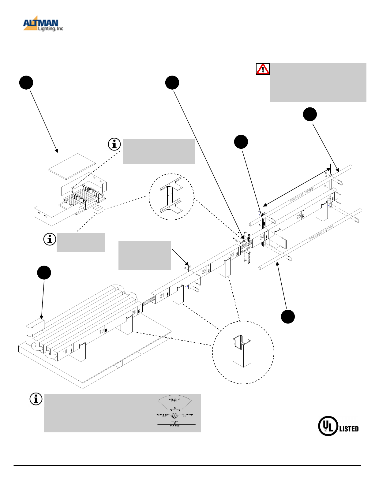
1
Position connector strip container near area
to be installed. Disassemble container so
that connector strip remains in bottom tray
without sides. Be sure of power feed location
and stage orientation (see below).
Use the cardboard shipping pylons as
stands to support the connector strip for
joining sections and attaching brackets.
DO NOT DISCARD-Cardboard
shipping pylons act as stands to
assist in assembly of the connector
strip
.
Boxes contains section
joiners and hanging
brackets.
Connect to power &
data sources and test.
6
Details page 4
Note:
Type 11 & 16 brackets
have one 3/4” diameter
hole at top for rigging
shackle.
Be sure to remove ALL protective
2
Connect all section with
steel section joiners
and hardware provided.
Details page 2
Install hanging
3
brackets onto
connector strip.
Details page 3
packaging materials from around
wires prior to joining sections together.
Attach connector
4
strip to rigging or
stage electrics
pipe.
m
u
m
i
x
a
M
s
r
e
t
n
e
C
’
5
After connector strip is
rigged and hanging, remove cardboard pylons
5
and attach Schedule 40 1
-1/2” pipe to hang lighting
fixtures. (pipe provided
by others)
Note:
Typical connector strip layouts have the circuit numbering facing the upstage side. Be certain of orientation
prior to unfolding and joining sections together. Diagram
above shows circuit numbering upstage and power
terminals stage Left.
Altman Lighting Co. Inc. 57 Alexander Street, Yonkers, NY 10701 1-800-4 ALTMAN
400/450* Series is UL
and cUL listed under
File E31501 for Stage
and Studio.
Rev 092511 49-0195
Page 2
400/450 Series Connector Strip Assembly Instructions
Extended length connector strips (exceeding 6’) are shipped partially assembled and folded. All internal wiring is
complete and all necessary components are included unless noted. Open each shipping container and check the
contents according to your packing slip. The wiring between sections should be undamaged and covered by protective plastic tubing. Metal parts should be free from scratches and dents. Contact your Altman Lighting representative
immediately if you discover any problems.
Tools required in assembling connector strip:
• #2 Philips screwdriver to assemble strip sections. (power driver w/torque control recommended)
• 1/8” Straight blade screwdriver to install wire feed into spring 20A circuits. (included in this package)
• 1/2” Hex deep socket & ratchet to assemble hanger brackets.
• Power drill and drill bits.
• Greenlee® or equivalent punch for conduit or metal strain relief. (strain relief not included)
• Large straight blade screwdriver for ground lug and 30A, 50A 60A, and 100A circuits
General assembly information
Fully assembled connector strips can be very long and difficult to move for installation. Assemble the connector strips
in an area with good access to the final installation point.
CAUTION: The section joiners are designed to hold the connector strip together for normal operation and not designed for unusual load stresses such as lifting entire length of strip from one end.
Assembling the connector strip sections
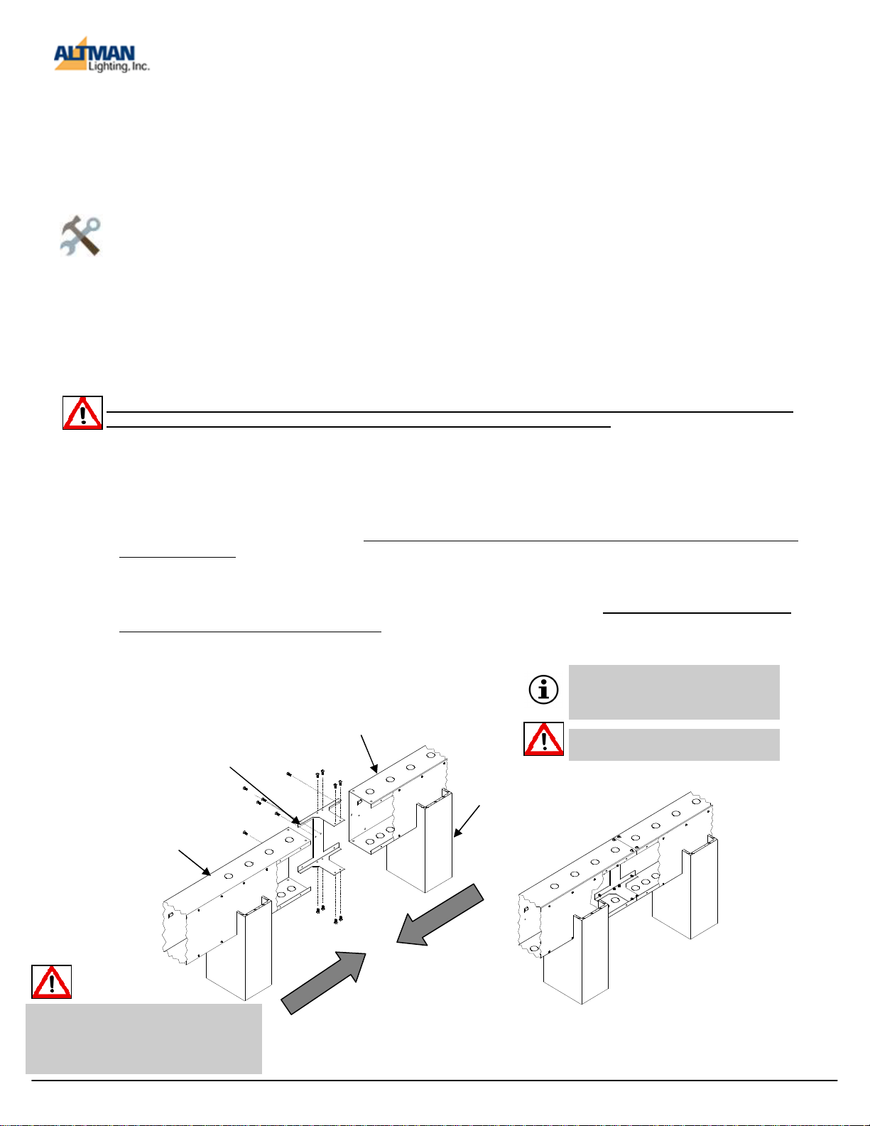
1. Identify which end of the connector strip is the terminal access end (Stage Left, Stage Right) and confirm that
this end is near the power source to be connected to. The terminal access end is identified by label:
TERMINAL ACCESS, and an orange sticker. Outlets and numbering typically face upstage.
2. Carefully remove the connector strip from the shipping container and stretch onto the floor with enough room
to assemble the entire connector strip. Use the cardboard shipping pylons as stands to assist in assembly of
the connector strip.
3. Each section requires fourteen (14) #10 self tapping screws and one steel joiner. (supplied with extra screws)
4. Attach steel joiner to 1st section to be joined with 7 screws and tighten.
5. Carefully slide mating 2nd section onto steel joiner and attach with 7 screws. Make sure electrical wires are
not being pinched or distorted in any way.
6. Repeat steps 4-5 above for all remaining sections.
Section Joiner
1st section
Be sure to remove ALL protective
packaging materials from around wires
prior to joining sections together.
Note:
A powered screw gun with torque control will
greatly speed the assembly of the connector
strip.
2nd section
DO NOT exceed 20 in/lbs of torque when
installing sheet metal screws.
Cardboard
Shipping
Pylon
Wires and DMX barrier panels not shown for clarity purposes.
Completed Section
2
Page 3
400/450 Series Connector Strip Assembly Instructions
Installing Hanging Brackets-All Types
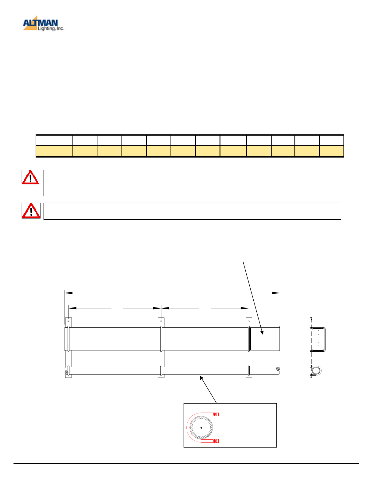
After assembling the connector strip sections, attach the hanging brackets to support it. Connector strips are
shipped with enough hangers for installation every five feet, with a hanger at each end. This is the maximum
spacing allowed. Hanging brackets may be included in connector strip packaging, or in some cases a separate
container. Confirm that all packaging materials are thoroughly inspected prior to disposal. Schedule 40 pipe is not
provided by Altman.
1. Starting at one end, fasten the hanger brackets onto the connector strip at intervals no greater than 5 feet.
DO NOT place brackets in a manner that would prevent access to TERMINAL ACCESS panel!
2. Use the provided 5/16”-18 fasteners and a 1/2” socket & ratchet to attach the hanging brackets to the con-
Table below: One pair of brackets, plus one additional bracket for each additional 5 feet.
Length 1’- 10’ 11’- 15’ 16’- 20’ 21’- 25’ 26’- 30’ 31’- 35’ 36’- 40’ 41’- 45’ 46’- 50’ 51’- 55’ 56’- 60’
Bracket Qty. 2 3 4 5 6 7 8 9 10 11 12
CAUTION: The installer must verify the mounting structure, support, or surface is capable of supporting the connector strip weight, in addition to any other loads hung from it. Always follow applicable building codes when attaching connector strips to structural elements of a building.
WARNING: Attaching hangers more than five feet apart risks structural failure of the connector strip.
DO NOT place brackets in a
manner that would prevent
access to TERMINAL AC-
To Specification
5' 5'
TERMINAL
ACCESS
ANSI Schedule 40 1-1/2" Pipe By Others:
External Dia. 1.900"
Internal Dia. 1.610"
Nominal Thickness: .145"
Weight/Foot Lbs.: 2.717
Maximum U-bolt dia: 2.000"
3
Page 4
400/450 Series Connector Strip Assembly Instructions
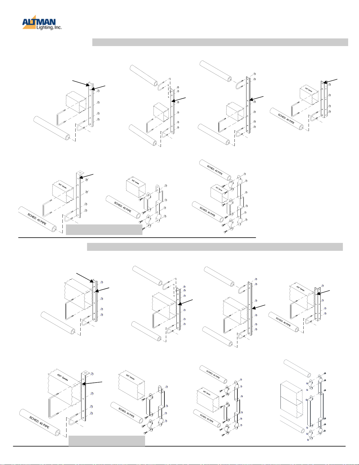
400 Series Brackets
400-TYPE-11
Single Pipe
Rigging Hole
3
0
0
*
S
e
r
i
e
s
S
C
H
E
D
.
4
0
P
I
P
E
400-TYPE-15
All Thread Bracket
For bracket types 11-13, be certain connector strip is mounted against FLAT SURFACE SIDE of bracket.
400-TYPE-12
Double Pipe
S
C
H
E
D
.
4
0
P
I
P
E
400-TYPE-13
Double Pipe
S
C
H
E
D
Extended
.
4
0
P
I
P
E
400-TYPE-14
90° Pipe Grid
*
*
3
0
0
*
S
e
r
i
e
s
S
C
H
E
D
.
4
0
P
I
P
E
400-TYPE-16
In-Line Single Pipe
*
S
C
H
E
D
.
4
0
P
I
P
E
400-TYPE-17
In-Line Double Pipe
3
0
0
*
S
e
r
i
e
s
*
*
*
=Hole not used on 400 series brackets
450Series Brackets
450-TYPE-11
Single Pipe
Rigging Hole
4
5
0
*
S
e
r
i
e
S
C
H
E
D
.
4
0
P
I
P
E
450-TYPE-15
All Thread Bracket
For bracket types 11-13, be certain connector strip is mounted against FLAT SURFACE SIDE of bracket.
450-TYPE-12
Double Pipe
S
C
H
E
D
.
4
0
P
I
P
E
s
*
S
C
H
E
D
.
4
0
P
I
P
450-TYPE-16
In-Line Single Pipe
4
5
0
*
S
e
r
i
e
s
E
*
450-TYPE-17
In-Line Double Pipe
450-TYPE-13
Double Pipe
Extended
S
C
H
E
D
.
4
0
P
I
P
E
4
5
0
*
S
e
r
i
e
S
C
H
E
D
.
4
0
P
I
P
E
s
*
*
450-TYPE-14
90° Pipe Grid
450-TYPE-17TB
In-Line Double Pipe
for Terminal Box
S
C
H
E
D
.
4
0
P
I
P
E
4
5
0
*
S
e
r
i
e
s
*
S
C
H
E
D
.
4
0
P
I
P
E
*
=Hole not used on 450 series brackets
4
Page 5
400/450 Series Connector Strip Assembly Instructions
WARNING: ALL ELECTRICAL WIRING AND CONNECTIONS MUST BE PERFORMED BY A
QUALIFIED ELECTRICIAN.
WARNING: This equipment MUST be grounded. Never defeat the ground conductor or
operate the equipment in the absence of a suitably installed ground conductor. Contact
the appropriate electrical inspection authority or an electrician if you are uncertain that
suitable grounding is available.
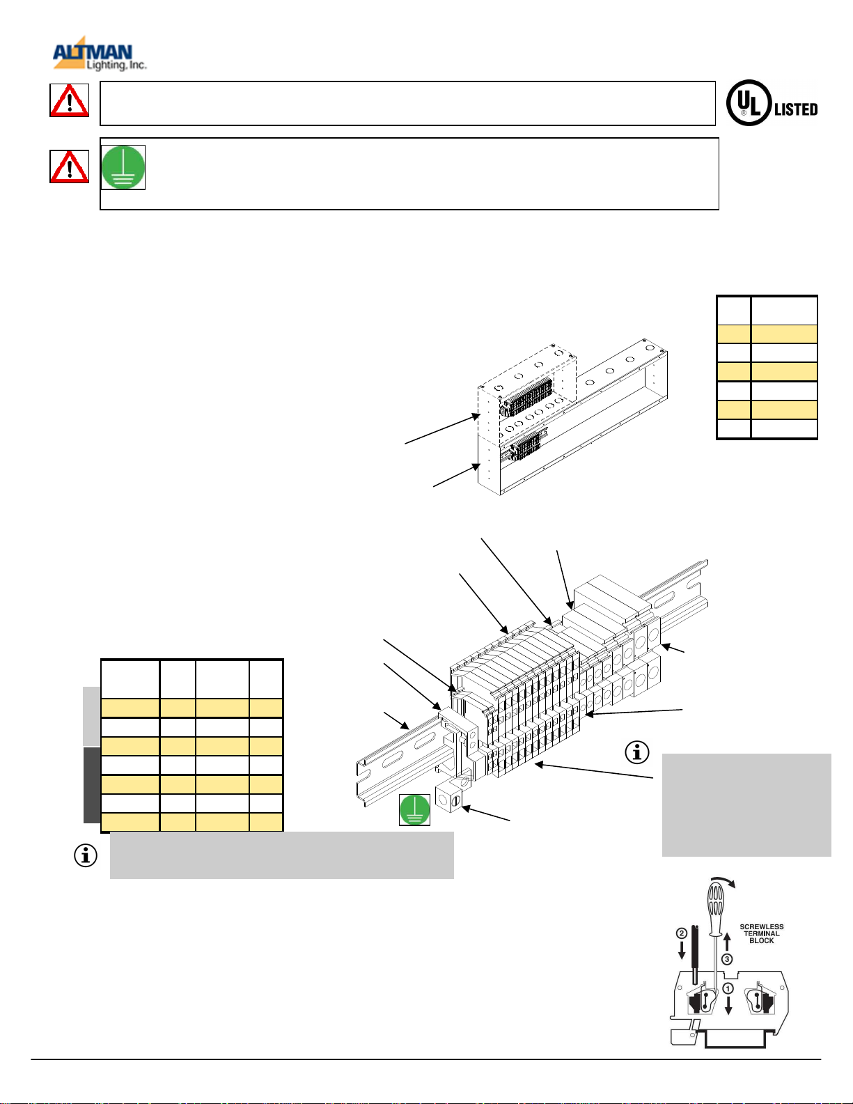
Electrical Connections
-From End Plates Each end plate has
(4) .125” diameter pilot holes. These pilot
holes act as centers for optimal positioning of
holes up to 2.5” in diameter for attaching wiring
strain relief devices into connector strips. Use
the pilot hole to drill the required size for a
Greenlee® or equivalent punch to obtain
proper hole size for your installation requirements. Use 1st hole from the top for data input, and 3rd hole from the top for AC power
connection.
Optional Extended Terminal Box
(400 Series 13 circuits or more.)
(450Series 25 circuits or more.)
DIN Rail Terminal Block System
The connector strip uses a 35MM
DIN rail modular terminal block system. Terminal blocks range from 15
amps to 115 amps depending on
product configuration when ordered.
Terminal Block Sizes
Note: Not all terminal blocks listed in chart below
may be present in connector strip.
Color Amps Wire
Spring Clamp
Beige* 15A 14 AWG 1/2”
Beige** 50A 8 AWG 1/2”
Gray** 50A 8 AWG** 1/2”
Screw Terminal
Orange 35A 10 AWG 3/8”
Blue 50A 8 AWG 1/2”
Yellow 65A 6 AWG 1/2”
Black 115A 2 AWG 3/4”
**Note: 50A spring clamp terminal blocks are used for 20A circuits.
The upsizing allows for contactors to use #10AWG or #8 AWG line
feed wire. All load side components are rated at 20A.
Size
Strip
Lengt
h
50A
Spring Clamp Terminal
Blocks (Gray or Beige, 12
*15A or 25A Spring Clamp
Terminal Blocks (Beige or Gray,
2 shown) For Data Power
Supply
End Stop (2)
35MM DIN Rail
-From Top The top surface at each end of
the connector strip has .875” knockouts.
Note: Minimal top clearance with double
pipe type brackets.
End Plates
50A Screw Terminal Blocks
(Blue, 2 shown)
75A Screw Terminal Blocks
(Yellow, 2 shown)
Contractor ground lug
4-14 AWG
400/450* Series is UL
and cUL listed under
File E31501 for Stage
and Studio.
Strain Relief Sizes
Trade
Hole Diameter
Size
Required
1/2 .875
3/4 1.125
1” 1.375
1-1/4” 1.750”
1-1/2” 2.000”
2” 2.500”
115A Screw Terminal Blocks
(Black, 2 shown)
30A Screw Terminal Blocks
(Orange, 2 shown)
*Note: 1st two terminal blocks
(beige or gray) are used to
power DMX/RDM Opto-Isolators
and Ethernet modules if so
equipped. This circuit requires a
constant, non dimmable source
of power.
Attaching Wires to Spring Clamp Type Terminal Blocks. (15A-50A Circuits Only)
20 Amp circuits are gray in color with white marking labels that accept up to maximum
8 AWG wire.
Step 1. Insert 1/8” wide flat blade screwdriver (supplied) into the square slot and push
all the way down so that screwdriver bottoms out.
Step 2. Insert the stripped wire into the oblong shaped hole.
Step 3. Remove screw driver to release spring clamp.
Step 4. Repeat steps 1-3 for all remaining connections.
5
Page 6
400/450 Series Connector Strip Assembly Instructions
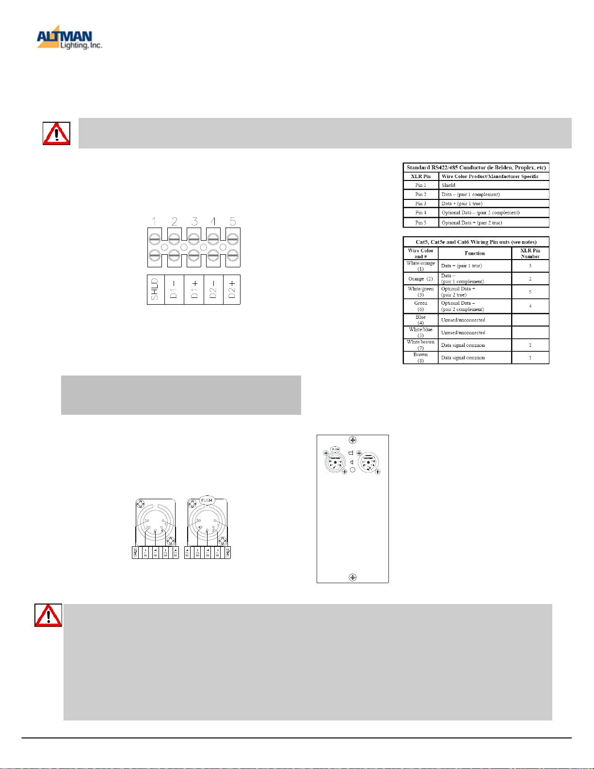
DMX512-A Wiring Guide (450 Series Only)
ANSI E1.27-2: STANDARD WIRING PRACTICE FOR PERMANENTLY
INSTALLED CONTROL CABLES FOR USE WITH ANSI E1.11 DMX512-A
Caution: All 5 data terminations are fully wired throughout the connector strip. Great care must be taken
to prevent the accidental connection of DMX equipment to non-DMX equipment.
DMX IN TERMINAL BLOCK STYLE
Passive DMX
Note: Terminal block style is fully insulated and not
required to be mounted. One terminal block used for
each passive universe.
DMX By Pass Switch Usage
Note on Category Wire Chart
This chart is intended for DMX512 cabling only - NOT DMX-over-Ethernet cabling. Great care must be taken to prevent
the accidental connection of DMX equipment to non-DMX equipment. The connection of DMX equipment to non-DMX
equipment such as Ethernet switches or telephone equipment may result in serious equipment damage and/or personal injury, as pins 4 and 5 may carry voltages of up to 48VDC or greater. Category wire is not recommended for loose or temporary cabling. The use of RJ45 connectors for DMX equipment should be restricted to patch bays in access controlled rooms
and should not be used for the direct connection of portable equipment.
Please be aware that some non-standard pin-outs are also in use (i.e. Color Kinetics).
DMX IN/OUT XLR 5 PIN STYLE
DMX IN 5 PIN
MALE
DMX IN 5 PIN
FEMALE
BYPASS LOOP
If the DMX outputs are not being
used, the position of the red switch
should be pushed in to IN position
(bypass).
If the DMX outputs ARE being
used, the red switch should be in
OUT position (loop). Data cables
should come out of the female connector, into the DMX device, and
then out of the DMX device, and
into the male connector. Not using
the return will disable all DMX
downstream.
6
 Loading...