

Page 1
TWO-WAY RADIO MODEL
PR561 BLT
PR562 BLT
Nothing Comes Close to a Cobra
®
Owner’s Manual
Part No. KEM-ML38404-01B
Printed in China
English
Page 2
Introduction
Making Life Easier and Safer
Staying in touch with your family and friends is
convenient and easy when using your microTALK
radio. Some of the many uses you will discover include:
Communicating with others while hiking, biking, and working; keeping
track of family and friends at a crowded public event; checking with
travel companions in another car; talking with neighbors; arranging
meeting spots with others while shopping at the mall.
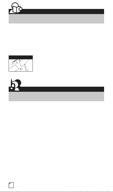
Belt Clip
Secure your microTALK
radio while on the go.
Carrying your microTALK
when using the belt clip or optional wrist strap.
The belt clip easily attaches to your belt, purse,
or backpack.
®
®
radio with you is easy
Customer Assistance
®
Product Service & Support
For any questions about operating this new Cobra branded product,
PLEASE CONTACT US FIRST… do not return this product to the retail
store. The contact information for support will vary depending on the
country in which you purchased and utilize the product.
To obtain warranty service or other information for products purchased
from Altis itself or through its authorized reseller or agent and utilized
in the U.S.A., please call our consumer support line at (866) 721-3805,
or email us at support@altistec.com. You will receive instructions
on how to ship the products at your expense to an Altis Global Limited
Authorized Service Center. To obtain service, you must include: (a) a
copy of your receipt, bill of sale or other comparable proof of purchase;
(b) a written description of the problem; and, most importantly; (c) your
address and telephone number.
For warranty and customer service information outside the US, please
contact your local dealer.
For further information needed on its features, please visit
www.cobrawalkietalkie.com for frequently
asked questions and the electronic manual.
A1
©2018 Altis Global Limited,
Atlanta, GA USA.
www.cobrawalkietalkie.com
Page 3
Introduction
Product Features
Product Features
1
11
15
14
16
2
12
M
E
C
M
S
E
10
9
8
4
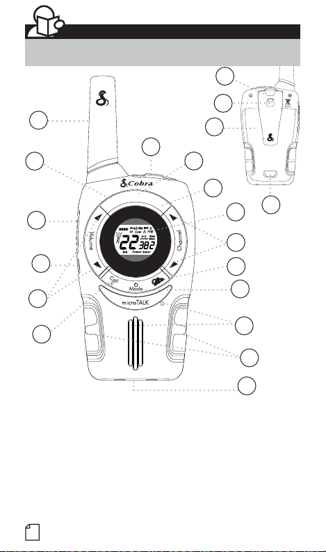
1. Antenna
2. External Speaker/
Microphone/ USB Charge Jack
3. Mode/Power Button
4. Call/Lock Button
5. Channel Up/Down Button
6. Backlit LCD Display
7. Speaker/Microphone
8. Volume Up/Down Button
9. LED Light Button
10. Talk Button
A2
R
x
a
a
n
g
M
e
L
O
/
I
W
H
S
c
a
n
13
17
6
5
20
3
7
18
19
11. Memory/Escape Button
12. Max Range Hi/Lo Button
13. Scan Button
14. Wrist Strap Connection
15. Belt Clip
16. Battery Compartment
17. Battery Door Latch
18. Rubberized Grips
19. LED Flashlight
20. Weather Button
Page 4
Features
• 22 Channels
• 10 Channel
Weather Radio
®
• Bluetooth
compatible
Bluetooth headset
pairing
• Weather Alert
• 121 Privacy Codes
(38 CTCSS codes/
83 DCS codes)
• Hands-Free Operation
(VOX)
®
• VibrAlert
Silent Paging
• Scan
Channels,
privacy codes
• Backlit LCD Display
• LED Flashlight
• Call Alert
Ten selectable
tones
• Button Lock
• Speaker/
Microphone/
Charge Jack
• Roger Beep
Selectable On/Off
• Battery/Power Saver
• Keystroke Tones
• Battery Level Indicator
• Low Battery
Audible Alert
• Auto Squelch
• Maximum
Range Extender
• Belt Clip
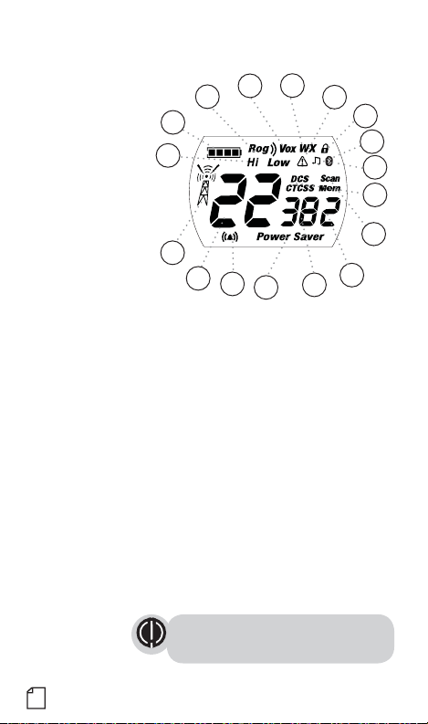
Backlit LCD Display
3
2
1
6
13
12
15
11
1. Battery Level Indicator
2. Roger Beep Icon
3. VOX Icon
4. Weather Icon
5. Lock Icon
6. Hi/Low Power Icon
7. DCS/CTCSS Icons
8. Scan/Memory Icon
9. Weather Alert Icon
10. DCS/CTCSS Privacy Code Numbers
11. Power Saver Icon
12. Channel Numbers
13. Receive/Transmit Icon
14. Memory Channel Number
15. VibrAlert
16. Key Tone Icon
17. Bluetooth Icon
Maximum range may vary and is based on
unobstructed line-of-sight communication
under ideal conditions.
®
/ Call Alert Icon
4
9
5
16
17
7
8
14
10
A3
Page 5
Caring for Your microTALK® Radio
Your microTALK
®
radio will give you years of trouble-free service
if cared for properly. Handle the radio gently. Keep the radio away from
dust. Never put the radio in water or in a damp place. Avoid exposure to
extreme temperatures.
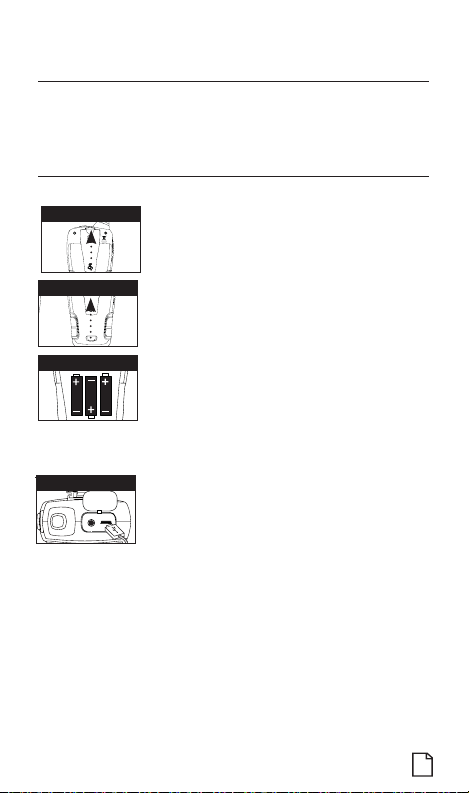
Installing Batteries
To install or replace batteries:
Remove Belt Clip
1. Remove belt clip by releasing belt clip
latch and sliding clip up.
2. Pull up on the battery door latch to remove the
battery compartment cover.
Pull Up Lock Latch
3. Insert the supplied three AA rechargeable batteries
or non-rechargeable alkaline batteries. Position
batteries according to polarity markings.
Insert Batteries
4. Replace battery compartment cover and
belt clip.
• Do not attempt to charge alkaline batteries.
• Do not mix old and new batteries.
• Do not mix alkaline, standard (carbon-zinc), or
rechargeable (Ni-Cd, Ni-MH, etc.) batteries.
•
•
Radio Charger Jack
To charge batteries in radio:
1. Check to see that the batteries have been inserted
properly.
2. Insert the cable into the charge jack located at the
top of the radio.
3. Plug the cable into USB power source.
Use only the supplied rechargeable batteries and charger for recharging
your Cobra microTALK
®
radio.
Cobra recommends your radio is turned off while being charged.
Non-rechargeable alkaline batteries can also be used in your radio.
1
Page 6
Operation
Using Your Radio
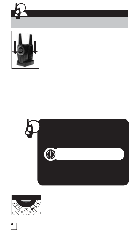
For charging microTALK radio in desktop charger:
1. Insert radio(s) into desktop charger as shown.
2. Insert the micro-USB cable into jack on back
of charger.
3. Plug the cable into USB-compatible power port.
For pluggable equipment, the socket-outlet shall
be installed near the equipment and shall be easily
If charging light is not on, check position of radio. Radio should be
upright. The charge indicator light will stay on as long as the radio is in
the charging well, and the light will go off when the charging is complete.
Note: To charge a single radio, you can bypass the desktop charger and
simply insert the micro-USB’s connector directly into the charge jack located
on the top of the radio.
The radio will display flashing battery icon while charging.
Cobra recommends your radio be turned off while being charged.
Non-rechargeable alkaline batteries can also be used in your radio.
Turning on Your microTALK® Radio
Mode/Power
2
accessible.
Quick Start
1. Press and hold the Mode/Power button
to turn on your radio.
2. Press the Channel Up or Channel Down
button to select a channel.
Both radios must be tuned to the same
channel/privacy code to communicate.
3. Press and hold the Talk button while
speaking into the microphone.
4. When finished talking, release the Talk
button and listen for a response.
Press and hold the Mode/Power button until you hear
a series of audible tones indicating the radio is on.
Your microTALK
ready to receive transmissions. The radio is always
in Standby mode except when the Talk, Call or
Mode/Power buttons are pressed.
®
radio is now in Standby mode,
•
Page 7
Battery Low
E
S
C
S
c
a
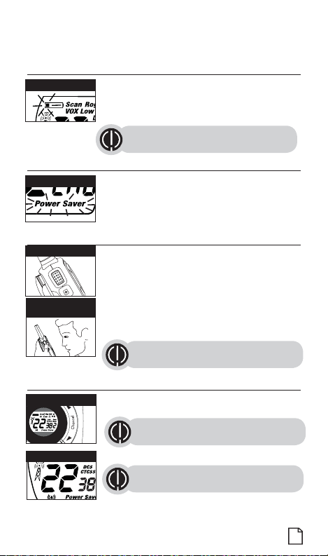
Battery Low
When battery power is low, the final bar in the Battery
Low icon will blink and an audible tone will sound twice
before the radio shuts off. Your batteries should be
replaced or recharged, if using rechargeable batteries.
The radio will display flashing battery icon
while charging.
Auto Battery Save
Battery Save Mode
If there are no transmissions within 10 seconds, the
radio will automatically switch to Battery Save mode
and the Power Saver icon will flash in the display.
This will not affect the radio’s ability to receive
incoming transmissions.
Communicating with Another Person
Talk Button
1. Press and hold the Talk button.
2. With the microphone about two inches (5 cm) from
your mouth, speak in a normal voice.
3. Release the Talk button when you have
Two Inches (5 cm)
from Mouth
finished talking and listen for a response.
You cannot receive incoming calls while
pressing the Talk button.
Both radios must be tuned to the same
channel/privacy code to communicate.
•
•
•
To Select a Channel
n
Channel Button
Channel Number
With the radio on, select any of the 22 channels by
pressing the Channel Up or Channel Down button.
Both radios must be tuned to the
same channel to communicate.
See page 20 for frequency allocations.
•
3
Page 8
Listening for a Response
Listening
Release the Talk button to receive incoming
transmissions. Your microTALK
®
radio is always in
Standby mode while the Talk or Call buttons are not
pressed.
To Adjust Volume
Volume Button
R
x
a
a
n
g
M
e
L
O
/
I
W
H
Press the Volume Up or Volume
M
S
E
c
a
C
M
S
n
E
Down button.
A double beep sound is used to indicate
the minimum and maximum volume levels
(1 through 8).
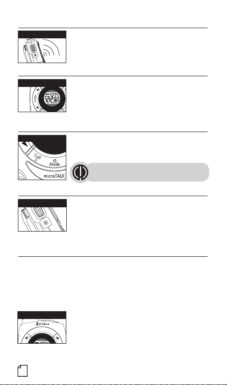
Call Button
Call Button
Press and release the Call/Lock button.
The other person will hear a three second call tone. This
tone is used only to establish voice communications.
See page 12 on how to select between ten
call tone settings.
LED/S.O.S. Flashlight
LED/S.O.S. Flashlight
Auto Squelch/Maximum Range
Your microTALK
and unwanted noise due to terrain, conditions or if you’ve reached your
Maximum Range limit.
You can temporarily turn off auto squelch or turn on maximum range
extender, allowing all signals to be received and extending the maximum
range of your radio.
Max Range Hi/Lo
x
a
M
/
I
H
M
E
C
M
S
E
Press and release the LED flashlight button below
the Talk button to use the LED flashlight located at
the bottom of the radio.
To activate S.O.S. function, press and hold the LED
flashlight button to turn on. Press and release to
turn off the flashlight or S.O.S. function.
®
radio will automatically shut off weak transmissions
To temporarily turn off auto squelch:
– Press and hold the Max Range Hi/Lo button
R
a
n
g
e
L
O
W
S
c
for at least five seconds until you hear
a
n
a beep which indicates the maximum
range extender is on.
•
•
•
•
•
4
Page 9
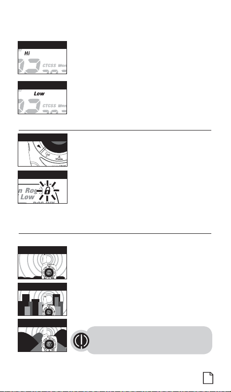
Hi Power Icon
Low Power Icon
– Press and hold the Max Range Hi/Lo button or
change channels to return to Standby mode.
To turn maximum range extender on:
– Press the Max Range Hi/Lo button for less than five
seconds. Hi icon will be displayed. (High power is
not valid on channels 8~14)
To turn maximum range extender off:
– Press Max Range Hi/Lo button until Low icon
displayed.
Lock Function
Lock Button
The Lock function locks the Channel Up, Channel
Down, Volume Up, Volume Down and Mode/Power
buttons to prevent accidental operation.
To turn the lock on or off:
Lock Icon
– Press and hold the Call/Lock button for
two seconds.
A beep sound is used to confirm your lock on or off
request. When in Lock mode,
the Lock icon will be displayed.
microTALK® Range
Your range will vary depending on terrain and conditions.
Maximum Range
Reduced Range
Reduced Range
In flat, open country your radio will
operate at maximum range.
Buildings and foliage in the path of the
signal can reduce the range of the radio.
Dense foliage and hilly terrain will further
reduce the range of the radio.
On Channels 8 through 14, your radio
automatically switches to low power, which
will limit the range the radio can communicate.
Remember, you can achieve maximum
range by using maximum range extender.
See page 4 for details.
•
•
5
Page 10

Operation
Mode Functions
Scrolling Through the Mode Function
By scrolling through the Mode function, you will be able to
select or turn on preferred features of your microTALK
scrolling through the Mode function, your radio features
will be displayed in the same predetermined order:
Mode/Power
Set CTCSS Privacy Codes
Set DCS Privacy Codes
Set Vox On/Off
Set Vox Sensitivity
Set Call Tones 1-10
Set VibrAlert On/Off
Set Roger Beep On/Off
Set Key Tones On/Off
Set Bluetooth On/Off
Set iVox Sensitivity
®
radio. When
(only valid when a Bluetooth headset connected)
Privacy Codes
Your microTALK® radio incorporates two advanced coded squelch
systems that can help to reduce interference from other users
on any given channel. CTCSS (Continuous Tone Coded Squelch
System) provides 38 privacy codes and DCS (Digitally Coded Squelch)
provides 83 privacy codes. This provides a total of 121 Privacy
Codes. Either system can be used on all channels, but both systems
cannot be used on the same channel at the same time.
To successfully communicate using a privacy code, both
the sending and receiving radios must be tuned to the same
channel and to the same privacy code system (CTCSS or DCS)
and privacy code number. Each channel will remember the last
privacy code system and number you select.
The privacy code 00 is not a privacy code, but allows all signals
to be heard on a channel that is set to 00 on both
the CTCSS and DCS systems
•
•
6
Page 11

Set CTCSS Privacy Codes
S
c
Mode/Power
To select a CTCSS privacy code:
1. After selecting a channel, press the Mode/Power
button until the CTCSS icon appears and the small
numbers next to the channel number flash on the
Privacy Code
display. (00 through 38)
If DCS is turned on at the channel selected,
the display will flash the
a
n
Channel Button
CTCSS icon and “OFF.” To switch from
DCS to CTCSS, press the Channel Up
or Channel Down button while the display is
flashing “OFF.” The display
will then show the small numbers flashing
and you will then be able
to proceed to step 2.
2. Press using the Channel Up or Channel Down button to select a
privacy code. You can hold the Up or Down button for fast advance.
3. When your desired CTCSS privacy code is displayed, choose one of the
following:
a. Press the Mode/Power button to enter the new setting and proceed
to other functions.
b. Press the Talk or Call/Lock button to return to Standby mode.
c. Do not press any buttons for 12 seconds to return to Standby mode.
•
7
Page 12

Set DCS Privacy Codes
M
a
x
R
a
n
g
e
Mode/Power
To select a DCS privacy code:
1. After selecting a channel, press the Mode/Power
button until the DCS icon appears and the small
numbers flash on the display (00 through 83).
DCS Privacy Code
L
O
/
I
W
H
S
Channel Button
c
a
n
If CTCSS is turned on at the channel
selected, the display will flash the DCS
icon and “OFF.” To switch from CTCSS to
DCS, press the Channel Up or Channel
Down button while the display is flashing
“OFF.” The display will then show the
small numbers flashing and you will then
be able to proceed to step 2.
2. Press using the Channel Up or Channel Down button to select a DCS
privacy code. You can hold the Up or Down button for fast advance.
3. When DCS privacy code is displayed, choose one of the following:
a. Press the Mode/Power button to enter the new setting and proceed
to other functions.
b. Press Talk or Call/Lock button to return to Standby mode.
c. Do not press any buttons for 12 seconds to return to Standby mode.
•
8
Page 13

Voice Activated Transmit (VOX)
E
M
E
H
I
/
L
O
W
S
W
S
In VOX mode, your microTALK® radio can be used “hands-free”, automatically
transmitting when you speak. You can set the VOX sensitivity level to fit the
volume of your voice and avoid transmissions triggered by background noise.
Mode/Power
VOX Icon
To turn VOX mode on or off:
1. Press the Mode/Power button until the VOX icon
flashes on the display. The current On or Off
setting is displayed.
2. Press the Channel Up or Channel Down
button to turn VOX On or Off.
3. Choose one of the following:
a. Press the Mode/Power button to enter the
new setting and proceed to other functions.
c
a
C
S
n
Channel Button
Mode/Power
VOX Sensitivity Level
c
a
n
Channel Button
b. Press Talk or Call/Lock button to return to
Standby mode.
c. Do not press any buttons for 12 seconds to return
to Standby mode.
To set VOX sensitivity:
1. Press the Mode/Power button until the VOX icon
flashes and the current sensitivity level is displayed.
The current VOX sensitivity level is displayed
with letters “L” and a Number 1 through 5,
with Number 5 being the most sensitive level
and Number 1 being the least sensitive level.
2. Press the Channel Up or Channel Down
button to change the setting.
3. Choose one of the following:
a. Press the Mode/Power button to enter the
new setting and proceed to other functions.
b. Press Talk or Call/Lock button to return to
Standby mode.
c. Do not press any buttons for 12 seconds to return
to Standby mode.
•
9
Page 14

10 Memory Locations
S
H
I
/
L
O
W
S
C
H
I
/
L
O
W
S
C
H
I
/
L
O
W
S
Your microTALK
your most frequently used channels and channel/privacy code
combinations. These Memory Locations can be selected individually or
can be scanned. (See page 18 for memory location scan.)
MEM/ESC Button
Channel Button
MEM/ESC Button
Channel Button
Memory Channel
Channel Button
®
radio has 10 Memory Locations for storing
To program a memory location:
1. Press and hold the MEM/ESC button until
R
x
a
a
n
g
M
e
L
O
/
I
W
H
M
E
C
M
S
E
c
a
n
M
E
C
M
S
E
c
a
n
Memory icon and the Memory Location blink
on the display.
2. Press the Channel Up or Channel Down button
to select the memory location (0 through 9).
If a location has been programmed before,
its associated channel/privacy code will be
shown on the display.
3. Press the MEM/ESC button to enter a
R
x
a
a
n
g
M
e
new memory location or edit an already
L
O
/
I
W
H
programmed memory location.
4. The channel numbers will flash on the display.
5. Press the Channel Up or Channel Down button
to select a channel (1 through 22).
6. Press the MEM/ESC button. The CTCSS icon
and privacy code numbers will flash on the
display.
7. Choose one of the following:
a. Press the Channel Up or Channel Down
button to select a CTCSS privacy code (00
c
a
n
through 38) for the channel.
b. Press the MEM/ESC button to switch from
CTCSS to DCS. The DCS icon and privacy code
numbers will flash on the display. The Channel
Up or Channel Down button can then be used
to select a DCS privacy code (00 through 83)
for the channel.
•
10
Page 15

If “oF” flashes in place of the privacy code numbers,
E
M
E
H
I
/
L
O
W
S
a privacy code is already set in the opposite (CTCSS
or DCS) system. Press the Channel Up or Channel Down
button to cancel the opposite code and select a privacy
code from the active system for the selected channel.
8. Choose one of the following:
a. Press the MEM/ESC button to enter the channel/privacy code
in the selected memory location. Radio then proceeds to next
memory location, which will blink.
b. Press the MEM/ESC button to save the current state of the Set
Memory Function, then press and hold the MEM/ESC button until
return to Standby mode.
MEM/ESC Button
E
M
E
Memory Channel
c
a
C
S
Channel Button
To recall a stored memory channel location:
R
x
a
a
n
g
M
e
1. Press the MEM/ESC button, the Memory icon
L
O
/
I
W
H
M
C
S
n
and the memory location number show on the
display.
2. Press the Channel Up or Channel Down button
to select a memory location (0 through 9).
If a location has been programmed before,
its associated channel/privacy code will be
shown on the display.
3. Press the MEM/ESC button to return to Standby
mode on the selected memory location.
11
Page 16

Ten Call Tone Settings
E
M
H
I
/
L
O
W
S
You can choose between ten different Call Tone Settings to transmit
a call alert.
Mode/Power
Call Tone Setting
To change a call tone setting:
1. Press the Mode/Power button until the
letter “C” and the current call tone number
(01 through 10) is displayed. The current
call tone will sound for three seconds.
2. Press the Channel Up or Channel Down button
to hear the other call tone settings.
3. Choose one of the following:
c
a
C
S
n
Channel Button
E
a. Press the Mode/Power button to enter the
new setting and proceed to other functions.
b. Press Talk or Call/Lock button to return to
Standby mode.
c. Do not press any buttons for 12 seconds to return
to Standby mode.
•
VibrAlert® and Call Alert
Call Tone On/
Vibrate On
Call Tone On/
Vibrate Off
12
Your microTALK
signals by sounding an audible call tone or an
audible tone with VibrAlert
®
radio can alert you to incoming
®
.
To change call settings:
1. Press the Mode button until the Call Setting icon
flashes on the display. The current setting (“01”
vibrate + ring, “02” ring only) is displayed.
2. Press the Channel Up or Channel Down button to
change the call setting.
3. Choose one of the following:
a. Press the Mode button to enter the new
setting and proceed to other functions.
b. Press Talk or Call/Lock button to return to
Standby mode.
c. Do not press any buttons for 12 seconds to return
to Standby mode.
•
Page 17

Roger Beep Confirmation Tone
M
E
M
H
I
/
L
O
W
S
E
M
H
I
/
L
O
W
S
Your listener will hear an audible tone when you release the Talk button.
This alerts the other party that you are finished talking and it is OK for
them to speak.
Mode/Power
Roger Beep Icon
To turn roger beep on or off:
1. Press the Mode/Power button until the
Roger Beep icon flashes. The current
on or off setting is displayed.
2. Press the Channel Up or Channel Down button
to select roger beep on or off.
3. Choose one of the following:
a. Press the Mode/Power button to enter the
new setting and proceed to other functions.
c
a
C
S
n
Channel Button
Channel Button
E
b. Press Talk or Call/Lock button to return to
Standby mode.
c. Do not press any buttons for 12 seconds to return
to Standby mode.
•
Key Tone On/Off
When Key Tone is On, an audible tone will sound each time a button
is pressed.
Mode/Power
To turn key tone on or off:
1. Current key tone status On/Off will flash.
2. Press the Channel Up or Channel Down button
to select key tone on or off.
3. Choose one of the following:
a. Press the Mode/Power button to enter the
new setting and proceed to other functions.
b. Press Talk or Call/Lock button to return to
Standby mode.
c. Do not press any buttons for 12 seconds to return
to Standby mode.
C
M
S
Channel Button
E
c
a
n
•
13
Page 18

Bluetooth On/Off
E
M
H
I
/
L
O
W
S
When Bluetooth is On, it can pair any compatible Bluetooth headset
automatically. Once a Bluetooth headset connected, your microTALK
®
radio can be used “hands-free”, automatically transmitting when you
speak to the microphone of the Bluetooth headset. You can set the iVOX
sensitivity level for Microphone of Bluetooth Headset to fit the volume of
your voice and avoid transmissions triggered by background noise. (See
page 15 for iVOX sensitivity settings.)
Mode/Power
To turn Bluetooth feature on or off:
1. Press the Mode/Power button until the
Bluetooth icon flashes on display. The current
On or Off setting is displayed.
Bluetooth Icon
2. Press either Channel Up or Channel Down
button to select Bluetooth On or Off.
3. Choose one of the following:
a. Press the Mode/Power button to enter the
c
a
C
S
n
Channel Button
E
Standby mode.
b. Press Talk or Call/Lock button to return to
Standby mode.
c. Do not press any buttons for 12 seconds to
return to Standby mode.
After turned on, a flashing Bluetooth icon is displayed, the radio is now
in Standby Pairing mode.
In order to save power, you may turn the
Bluetooth feature Off if no Bluetooth
Headset needed to connect.
Pairing Bluetooth headset
To avoid pairing to wrong device,
please switch off all other Bluetooth
devices before pairing process.
•
•
14
Page 19

Bluetooth Icon (Flashing)
E
M
H
I
/
L
O
W
S
1. Follow the Bluetooth headset manufacturer’s
instruction to enable its Bluetooth function and
enter to pairing mode.
2. Once the Bluetooth function is enabled, the radio
will try to search and pair any compatible Bluetooth
Bluetooth Icon (Solid)
headset. Successful pairing will be indicated by a
icon
solid Bluetooth
displayed.
Go to www.cobrawalkietalkie.com for compatibility
information. Work best on Plantronics Voyager
V5200 and M165, Motorola H720x & Jabra
SUPREME Bluetooth headsets.
3. Once a Bluetooth headset connected, iVOX mode
is ready to use. You may speak to the microphone
of the Bluetooth headset, it will be transmitting
automatically.
iVOX Sensitivity (For Bluetooth Headset)
Bluetooth Icon (Solid)
You can set the iVOX sensitivity level for
Microphone of Bluetooth Headset to fit the volume
of your voice and avoid transmissions triggered by
background noise.
Mode/Power
To adjust iVOX sensitivity for Microphone of
Bluetooth Headset:
1. After connected to a Bluetooth headset, press
the Mode/Power button until the Bluetooth
iVOX Sensitivity Level
icon flashes and the current sensitivity level is
displayed. (iVOX sensitivity level menu will be
valid only when a Bluetooth headset connected.)
The current iVOX sensitivity level is
displayed with letters “A” and a Number 1
c
a
C
S
n
Channel Button
E
through 20, with Number 20 being the
most sensitivity level and Number 1 being
the least sensitivity level.
Press the Channel Up or Channel Down button
2.
to change the setting.
3.
Press Scan button to save the current value of
the sensitivity.
Note: The default
sensitivity is 12
iVOX
Scan Button
x
L
/
I
R
a
n
g
e
O
W
S
c
a
n
•
15
Page 20

Channel Scan
M
H
I
/
L
O
W
S
Your microTALK
Scan Button
R
x
a
n
g
e
L
O
/
W
Scan Channels
E
C
S
Channel Button
E
During scanning (while receiving an incoming transmission),
you can choose from the following:
a. Press and hold the Talk button to communicate on that channel. Your
radio will remain on that channel and return to Standby mode.
b. Press the Channel Up or Channel Down button to resume
scanning channels.
®
radio can automatically scan channels.
To scan channels:
S
c
a
n
c
a
1. Press and release the Scan button, the Scan icon
and the channel numbers appear on the display.
2. Press and hold the Scan button to begin scanning
channels.
The radio ignores specific privacy
codes while scanning channels.
The Scan icon will continue to be displayed when
n
scan is on. Your radio will continue to scan all
channels and stop if an incoming transmission is
detected. Your radio will remain on that channel for
4 seconds.
c. Press and hold the Scan button to return to Standby.
•
16
Page 21

Privacy Code Scan
M
S
H
I
/
L
O
W
S
Your microTALK
(either CTCSS 01 through 38 or DCS 01 through 83) within one channel.
Only one set of privacy codes (CTCSS or DCS) can be scanned at a time.
Scan Button
R
x
a
n
g
e
L
O
/
I
W
C
Channel Button
®
radio can automatically scan the Privacy Codes
To scan privacy codes:
S
c
a
n
c
a
n
1. While in Standby mode, press and release the
Scan button twice (CTCSS) or three times (DCS)
until the CTCSS or DCS icon and numbers are
flashing.
2. Press and hold the Scan button to begin scanning
privacy codes within the selected channel.
•
Select Channel
The Scan icon will continue to be displayed when
privacy code scan is on. Your radio will continue
to scan privacy codes and stop as an incoming
transmission is detected. Your radio will remain on
that channel/privacy code for 6 seconds.
Scan Privacy Codes
During scanning (while receiving an incoming transmission),
you can choose from the following:
a. Press and hold the Talk button to communicate on that privacy code
within the selected channel. Your radio will remain on that privacy
code and return to Standby mode.
b. Press the Channel Up or Channel Down button to resume
scanning.
c. Press and hold the Scan button to return to Standby.
17
Page 22

Memory Scan
S
M
H
I
/
L
O
W
S
W
S
Your microTALK
locations.(See page 10 for setting memory locations)
®
radio can automatically scan the stored memory
•
MEM/ESC Button
M
E
M
S
E
Scan Button
R
x
a
n
g
e
L
O
/
I
W
S
c
a
n
E
c
a
C
S
Channel Button
E
NOAA* All Hazards Radio Channels
You can use your microTALK
Radio channels transmitting in your area.
Weather Button
Hazards Radio Icon
c
a
n
Channel Button
To scan memory locations:
R
x
a
a
n
g
M
e
1. Make sure 2 or more memory locations
L
O
/
I
W
H
C
n
programmed already.
2. Press and release the MEM/ESC button to enter
Memory mode from Standby mode.
Memory icon and the Memory Location show
on the display.
3. Press and release the Scan button, Scan
icon and Memory icon will be displayed
simultaneously and then begin scanning stored
channel locations.
The Scan icon will continue to be displayed when
Memory Scan is On.
Your radio will continue to scan memory locations
and stop as an incoming transmission is detected.
Your radio will remain on that stored channel/
privacy code for 6 seconds.
®
radio to listen to NOAA All Hazards
To listen to All Hazards Radio channels:
1. Press the Weather button until the All Hazards
Radio icon and the currently selected All Hazards
Radio channel are displayed.
2. Use the Channel Up or Channel Down
button to change All Hazards Radio channels.
3. The All Hazards Radio icon will continue to
be displayed when All Hazards Radio is on.
4. To exit All Hazards Radio, press and hold the
Weather button until “All Hazards Radio” icon
is off.
•
18
*National Oceanographic and Atmospheric Administration
Page 23

Weather (WX) Alert Mode
W
S
Turning On the Weather Alert function will allow your radio to automatically
receive NOAA weather signals and warnings from designated weather
broadcast stations. If the radio is turned ON, it will alert to Weather and other
emergency alerts broadcast by NOAA.
This feature is set
to OFF by default.
Make sure the strongest
Weather channel is selected
for your area using the channel
selection in the previous menu.
•
Weather Button
Channel Button
Weather Alert Icon
To turn Weather Alert On or Off:
1. Press the Weather button twice until the
Weather Alert icon flashes on the display. The
c
a
n
current On or Off setting is displayed.
2.
Press the Channel Up and Channel Down button
to turn Weather Alert On or Off.
Press and hold the
3.
the new setting and exit the Weather Alert Mode
and return to Standby mode.
Weather button again to save
19
Page 24

Warranty & Trademark Acknowledgment
Frequency Allocation
A = Channel No. for 22 Channel Models
B = Frequency in MHz
C = Power Output
AB C
1 462.5625 High
2 462.5875 High
3 462.6125 High
4 462.6375 High
5 462.6625 High
6 462.6875 High
7 462.7125 High
8 467.5625 Low
9 467.5875 Low
10 467.6125 Low
11 467.6375 Low
12 467.6625 Low
13 467.6875 Low
14 467.7125 Low
15 462.5500 High
16 462.5750 High
17 462.6000 High
18 462.6250 High
19 462.6500 High
20 462.6750 High
21 462.7000 High
22 462.7250 High
IMPORTANT NOTICE:
WARNING: Changes or modifications to this unit not expressly approved by the party responsible for
compliance could void the user’s authority to operate the equipment.
This device complies with Part 15 of the FCC Rules. Operation is subject to the following two conditions:
1) This device may not cause harmful interference, and 2) this device must accept any interference
received, including interference that may cause undesired operation.
NOTE: This equipment has been tested and found to comply with the limits for a Class B digital device,
pursuant to part 15 of the FCC Rules. These limits are designed to provide reasonable protection against
harmful interference in a residential installation. This equipment generates, uses and can radiate radio
frequency energy and, if not installed and used in accordance with the instructions, may cause harmful
interference to radio communications.
However, there is no guarantee that interference will not occur in a particular installation. If this
equipment does cause harmful interference to radio or television reception, which can be determined
by turning the equipment off and on, the user is encouraged to try to correct the interference by one or
20
Important: Please note that Cobra GMRS
•
Page 25

more of the following measures:
• Reorient or relocate the receiving antenna.
• Increase the separation between the equipment and receiver.
• Connect the equipment into an outlet on a circuit different from that to which the receiver is connected.
• Consult the dealer or an experienced radio/TV technician for help.
Safety Information For microTALK
Your wireless handheld portable transceiver contains a low power transmitter. When the Talk button is
pushed, it sends out radio frequency (RF) signals. The device is authorized to operate at a duty factor not
to exceed 50%. In August 1996, the Federal Communications Commissions (FCC) adopted RF exposure
guidelines with safety levels for handheld wireless devices.
Important:
FCC RF Exposure Requirements: For body-worn operation, this radio has been tested and meets the FCC
RF exposure guidelines when used with Cobra accessories supplied or designated for this product. Use
of other accessories may no ensure compliance with FCC RF exposure guidelines. Use only the supplied
antenna. Unauthorized antennas, modifications, or attachments could damage the transmitter and may
violate FCC regulations.
Normal Position:
Hold the transmitter approximately 25 mm from your face and speak in a normal voice, with the
antenna pointed up and away.
ISEDC WARNING
This device complies with ISEDC license-exempt RSS standard(s). Operation is subject to the
following two conditions: (1) this device may not cause interference, and (2) this device must accept
any interference, including interference that may cause undesired operation of the device.
Under ISEDC regulations, this radio transmitter may only operate using an antenna of a type and
maximum (or lesser) gain approved for the transmitter by ISEDC. To reduce potential radio
interference to other users, the antenna type and its gain should be so chosen that the equivalent
isotropically radiated power (e.i.r.p.) is not more than that necessary for successful communication.
The applicant is responsible for providing proper instructions to the user of the radio device, and any
usage restrictions, including limits of exposure durations. The user manual shall provide installation
and operation instructions, as well as any special usage conditions, to ensure compliance with SAR
and/or RF eld strength limits. For instance, compliance distance shall be clearly stated in the user
manual.
Cetappareil est conformeaux normes RSSexemptes delicence ISEDC. Sonfonctionnement est
soumisauxdeuxconditionssuivantes:(1)cetappareilnedoitpasprovoquerd'interférenceset(2)
cetappareil doit accepter toute interférence, ycompris les interférences pouvantentraîner un
fonctionnementindésirabledel'appareil.Envertudesréglementations
nepeut fonctionnerqu'avec uneantenned'un type etun gain maximal(ou inférieur)approuvé
pour l'émetteur par l'ISEDC. Pour réduire les interférences radio potentielles avec d’autres
utilisateurs,letype d’antenneetson gain doiventêtre choisisde manièreà ceque lapuissance
isotrope rayonnée
communicationréussie.
Ledemandeurestresponsablede fournirdesinstructionsappropriéesà l'utilisateurdudispositif
radioetdetou terestrictiond'utilisation,ycomprisleslimitesdeladuréed'exposition.Lemanuel
del'utilisateurdoit fournirdesinstructionsd'installationet
d'utilisationspéciales,pourassurerlaconformitéavecleslimites dechampdeSARet/ouRF.Par
exemple,ladistancedeconformitédoitêtreclairementindiquéedanslemanueld'utilisation.
Important:
Exigences de la FCC/ISEDC concernant l’exposition aux champs électro-magnétiques RF (radiofréquences):
En ce qui concerne le fonctionnement de l’appareil porté sur le corps de l’utilisateur, les tests effectués ont
permis de vérier que cet émetteur-récepteur satisfait aux directives FCC/ISEDC limitant l’exposition aux champs
électro-magnétiques RF lorsqu’il est utilisé avec les accessoires Cobra fournis ou conçus pour ce produit;
l’utilisation d’autres accessoires peut ne pas garantir le respect des critères des directives FCC/ISEDC limitant
l’exposition aux champs électro-magnétiques RF. Utiliser l’appareil uniquement avec l’antenne fournie.
L’emploi d’une antenne non homologuée ou modiée, ou d’accessoires non autorisés, pourrait faire subir
des dommages à l’appareil, et peut violer les prescriptions de la réglementation FCC/ISEDC.
Position normale:
Tenir l'émetteur à environ 25 mm de la bouche et parler normalement, l'antenne étant éloignée et
dirigée vers le haut.
®
Radios
ISEDC,cetémetteurradio
équivalente (e.i.r.p.) ne soit pas supérieure à celle nécessaire à une
d'utilisation,ainsique desconditions
21
Page 26

Warranty & Trademark Acknowledgment
Limited One-Year Warranty
Altis Global Limited warrants to the original consumer purchaser only that this product
and the component parts thereof, will be free from defects in workmanship and
materials for a period of one year from the date of first consumer purchase. During this
period, Altis will, repair or replace, at its sole option and discretion, this product or any
defective parts. Altis’ liability hereunder shall be limited to repair or replacement of the
defective part or parts, and such correction shall constitute a fulfilment of all of Altis’
warranties hereunder.
This limited warranty is only valid for the original consumer purchaser in limited
jurisdictions and is not transferrable. This limited warranty will automatically terminate
prior to expiration if this product is sold or otherwise transferred to another party.
The product must be purchased from Altis or an authorized dealer or the warranty is
void. This limited warranty is valid only for products purchased and utilized in specific
jurisdictions. Please visit our website at www.cobrawalkietalkie.com for a list of
jurisdictions wherein this limited warranty is valid.
This limited warranty does not cover damage due to misuse, abuse, negligence, acts of
God, accident, commercial use or modification of, or to any part of this product. This
warranty does not cover damage due to improper operation, maintenance or installation;
ordinary wear and tear; or attempted alterations or repairs by anyone other than Altis
or someone authorized by Altis to do warranty work. Any unauthorized alterations or
repairs will void this warranty. This limited warranty does not cover product sold AS
IS or WITH ALL FAULTS. This limited warranty is invalid if the factory applied serial
number or date stamp has been altered, defaced or removed from this product. This
limited warranty does not cover product purchased or utilized in a jurisdiction not
covered.
The procedure for obtaining service and support, and the applicability of this warranty,
will vary depending on the country or jurisdiction in which you purchase and utilize
the product. For details on obtaining product service, support and other warranty
information please visit www.cobrawalkietalkie.com.
This warranty gives you specific legal rights, and you may also have other rights which
vary from state to state and country to country.
EXCEPT AS EXPRESSLY SET FORTH IN THIS WARRANTY, ALTIS MAKES NO OTHER
WARRANTIES, EXPRESSED OR IMPLIED, INCLUDING ANY IMPLIED WARRANTIES OF
MERCHANTABILITY AND FITNESS FOR A PARTICULAR PURPOSE. ALTIS EXPRESSLY
DISCLAIMS ALL WARRANTIES NOT STATED IN THIS LIMITED WARRANTY. ANY IMPLIED
WARRANTIES THAT MAY BE IMPOSED BY LAW ARE LIMITED TO THE TERMS OF THIS
EXPRESSED WARRANTY.
LIMITATION OF REMEDIES AND DAMAGES. REPAIR OR REPLACEMENT AS PROVIDED
UNDER THIS WARRANTY IS THE EXCLUSIVE REMEDY OF THE CONSUMER. ALTIS
SHALL NOT BE LIABLE FOR ANY INCIDENTAL OR CONSEQUENTIAL DAMAGES,
INCLUDING BUT NOT LIMITED TO ATTORNEYS’ FEES AND/OR COSTS OF LITIGATION,
•
22
Page 27

FOR BREACH OF ANY EXPRESS OR IMPLIED WARRANTY ON THIS PRODUCT. ALTIS IS
NOT LIABLE FOR ANY DAMAGES CAUSED BY THE PRODUCT OR BY THE PRODUCT TO
PERFORM, INCLUDING ANY LOST PROFITS, LOST SAVINGS, INCIDENTAL DAMAGES,
OR CONSEQUENTIAL DAMAGES. ALTIS IS NOT LIABLE FOR ANY CLAIM MADE BY
A THIRD PARTY OR MADE BY YOU FOR A THIRD PARTY. THIS LIMITATION APPLIES
WHETHER DAMAGES ARE SOUGHT, OR A CLAIM MADE, UNDER THIS WARRANTY OR AS
A TORT CLAIM (INCLUDING NEGLIGENCE OR STRICT PRODUCT LIABILITY), A CONTRACT
CLAIM, OR ANY OTHER CLAIM. THIS LIMITATION CANNOT BE WAIVED OR AMENDED
BY ANY PERSON. THIS LIMITATION OF LIABILITY WILL BE EFFECTIVE EVEN IF ALTIS
OR AN AUTHORIZED REPRESENTATIVE OF ALTIS HAS BEEN ADVISED BY YOU OF THE
POSSIBILITY OF ANY SUCH DAMAGES.
Some states and countries do not allow limitations on how long an implied warranty
lasts and do not allow the exclusion or limitation of incidental or consequential
damages, so the above limitations may not apply to you. This warranty gives you
specific legal rights, and you may also have other rights which vary from state to state
and country to country.
Provided that the product was purchased from Altis itself or through its authorized
reseller or agent and utilized in the U.S.A., Altis will, without charge, repair or replace,
at its option, defective products, products or component parts upon delivery to the
authorized Altis Global Limited Authorized Service Center, accompanied by proof of the
date of first customer purchase, such as a duplicated copy of a sales receipt.
You must pay any initial shipping charges required to ship the product for warranty
service, but the return charges, to an address in the U.S.A, will be at Altis’ expense, if
the product is under warranty.
For Products Purchased Outside the U.S.A.
Please contact your authorized local reseller or agent for warranty information.
Trademark Acknowledgement
Manufactured, distributed, or sold by Altis Global Limited, official licensee for this
product. Cobra®, microTalk®, Nothing Comes Close to a Cobra®, and the snake
design are registered trademarks of Cobra Electronics Corporation, USA. Cobra
Electronics Corporation™ is a trademark of Cobra Electronics Corporation, USA. All
other product or service names are the property of their respective owners.
© Cobra Electronics Corporation, USA 2018. All rights reserved.
•
23
 Loading...